ECU ISUZU TROOPER 1995 Owner's Manual
[x] Cancel search | Manufacturer: ISUZU, Model Year: 1995, Model line: TROOPER, Model: ISUZU TROOPER 1995Pages: 1928
Page 579 of 1928
I••IINSTALLATION
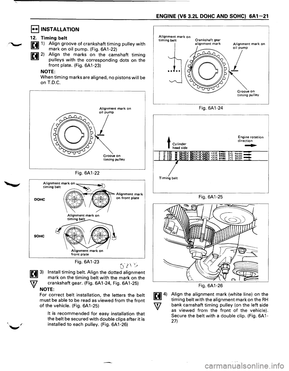
12. Timing belt
1£4111) Align groove of crankshaft timing pulley with
mark on oil pump. (Fig. 6A 1-22)
1£4112) Align the marks on the camshaft timing
pulleys with the corresponding dots on the
front plate. (Fig. 6A 1-23)
NOTE:
When timing marks are aligned, no pistons will be
on T.D.C.
,-----------------------------,
Fig. 6A1-22
Groove on timing pulley
Alignment mark on~ ad]
timing belt ·~Alignment mark
DOHC ", ' on front plate Q',
SOHC
Fig. 6A1-23 '"-) ,.· (.)~\,'j
1£4113) Install timing belt. Align the dotted alignment
mark on the timing belt with the mark on the
W crankshaft gear. (Fig. 6A1-24, Fig. 6A1-25)
NOTE:
For correct belt installation, the letters the belt
must be able to be read as viewed from the front
of the vehicle. (Fig. 6A 1-25)
It is recommended for easy installation that
the belt be secured with double clips after it is
installed to each pulley. (Fig. 6A 1-26)
ENGINE (V6 3.2L DOHC AND SOHC) 6A1-21
Alignment mark on timing belt Crankshaft gear alignment mark
L~---
t Cylinder head side
Timing belt
Fig. 6A1-24
Fig. 6A1-25
Fig. 6A1-26
Engine rotation direction
~
Align the alignment mark (white line) on the
timing belt with the alignment mark on the RH
bank camshaft timing pulley (on the left side
as viewed from the front of the vehicle).
Secure
the belt with a double clip. (Fig. 6A 1-
27)
Page 589 of 1928
I•• I INSTALLATION
32. Hydraulic lash adjuster (HLA)
• Install the HLA per removal mark.
31. Swing arm
• Install the swing arm per removal mark.
30. Camshaft
~ • Tighten camshaft bracket fixing bolts to the
~ specified torque.
~·
~·
Torque N-m (lb-in) I 10 (87)
Tighten front plate fixing bolts to the specified
torque.
Torque
N-m (lb·ft) I 19 (14)
Tighten camshaft pulley fixing bolts to the
specified torque.
Torque
N-m (lb·ft) I 63 (46)
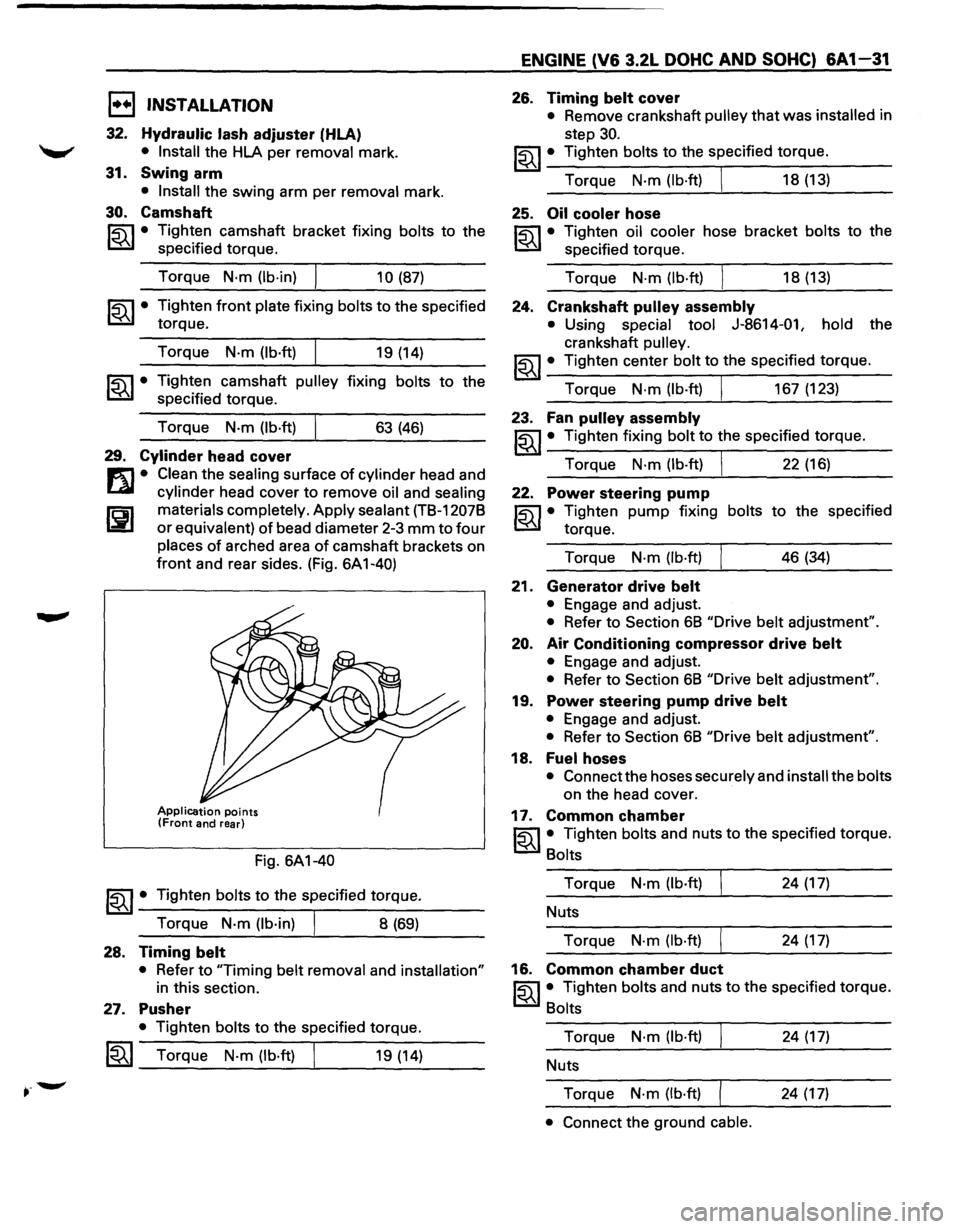
29. Cylinder head cover
m • Clean the sealing surface of cylinder head and
l....al cylinder head cover to remove oil and sealing
I'Ei1 materials completely. Apply sealant (TB-1207B
La:.l or equivalent) of bead diameter 2-3 mm to four
places of arched area of camshaft brackets on
front and rear sides. (Fig. 6A 1-40)
Application points (Front and rear)
Fig. 6A1-40
~~~· Tighten bolts to the specified torque.
Torque
N·m (lb·in) I 8 (69)
28. Timing belt
• Refer to "Timing belt removal and installation"
in this section.
27. Pusher
• Tighten bolts to the specified torque.
~~~ Torque N-m (lb·ft) 19 (14)
ENGINE (V6 3.2L DOHC AND SOHC) 6A1-31
26. Timing belt cover
• Remove crankshaft pulley that was installed in
step
30.
~~~· Tighten bolts to the specified torque.
Torque
N·m (lb·ft) J 18 (13)
25. Oil cooler hose
~ • Tighten oil cooler hose bracket bolts to the
~ specified torque.
Torque
N-m (lb-ft) I 18 (13)
24. Crankshaft pulley assembly
• Using special tool J-8614-01, hold the
crankshaft
pulley.
~~~· Tighten center bolt to the specified torque.
Torque
N·m (lb·ft) I 167 (123)
23. Fan pulley assembly
~~~· Tighten fixing bolt to the specified torque.
Torque
N·m (lb-ft) I 22 (16)
22. Power steering pump
~ • Tighten pump fixing bolts to the specified
~ torque.
Torque
N-m (lb·ft) 46 (34)
21. Generator drive belt
• Engage and adjust.
• Refer to Section 6B "Drive belt adjustment".
20. Air Conditioning compressor drive belt
• Engage and adjust.
• Refer to Section 6B "Drive belt adjustment".
19. Power steering pump drive belt
• Engage and adjust.
• Refer to Section 6B "Drive belt adjustment".
18. Fuelhoses
• Connect the hoses securely and install the bolts
on the head cover.
17. Common chamber
~~~· Tighten bolts and nuts to the specified torque.
Bolts
Torque N·m (lb-ft) 24 (17)
Nuts
Torque
N-m (lb·ft) 24 (17)
16. Common chamber duct
~~~· Tighten bolts and nuts to the specified torque.
Bolts
Torque N·m (lb-ft) 24 (17)
Nuts
Torque
N-m (lb·ft) 24 (17)
• Connect the ground cable.
Page 593 of 1928
1••1 INSTALLATION
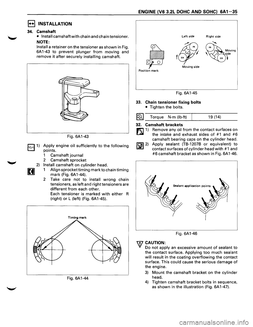
34. Camshaft
u
• Install camshaft with chain and chain tensioner.
NOTE:
Install a retainer on the tensioner as shown in Fig.
6A 1-43 to prevent plunger from moving and
remove
it after securely installing camshaft.
2)
Fig. 6A1-43
Apply engine oil sufficiently to the following
points.
1 Camshaft
journal
2 Camshaft sprocket
Install camshaft on cylinder head.
1
Align sprocket timing mark to chain timing
mark (Fig. 6A1-44).
2 Take care
not to install wrong chain
tensioners,
as left and right tensioners are
different from each other.
Each tensioner
is marked with either R
(right)
or L (left) (Fig. 6A1-45).
Timing mark
Fig. 6A1-44
ENGINE (V6 3.2L DOHC AND SOHC) 6A1-35
Left side
Moving side
Position mark
Fig. 6A1-45
33. Chain tensioner fixing bolts
• Tighten the bolts.
1~1 Torque N·m (lb·ft)
32. Camshaft brackets
Right side
19 (14)
m 1) Remove any oil from the contact surfaces on
l..QI the intake and exhaust sides of #1 and #6
camshaft bearing caps on the cylinder head.
~~~2) Apply sealant (TB-12078 or equivalent) to
contact surfaces of cylinder head with # 1 and
#6 camshaft bracket as shown in Fig. 6A 1-46.
Sealant application points
Fig. 6A1-46
U7 CAUTION:
VI Do not apply an excessive amount of sealant to
the contact surface. Applying too much sealant
will result in the coating overflowing the contact
surface. This
could cause the serious damage of
the engine.
3) Mount the camshaft bracket on the cylinder
head.
4) Tighten camshaft bracket bolts in sequence,
as shown in the illustration (Fig. 6A1-47).
Page 595 of 1928
19. Power steering pump drive belt
• Engage and adjust.
• Refer to Section 6B "Drive belt adjustment".
18. Fuel hoses
• Connectthe hoses securely and install the bolts
on the head cover.
17. Common chamber
~~~ • Tighten bolts and nuts to the specified torque.
Bolts
Torque N·m (lb·ft) 24 (17)
Nuts
Torque
N·m (lb·ft) 24 (17)
16. Common chamber duct
~~~ • Tighten bolts and nuts to the specified torque.
Bolts
Torque N·m (lb·ft) 24 (17)
Nuts
Torque
N·m (lb·ft) 24 (17)
• Connect the ground cable.
15. Exhaust Gas Recirculation Valve assembly
~~~ • Tighten bolts to the specified torque.
Exhaust Gas
Recirculation Valve side
Torque
N·m (lb·in) 8 (69)
Exhaust manifold side
Torque
N·m (lb·ft) 28 (21)
14. Evaporative Emission Canister Purge hose
13. Fuel Pressure
Control Valve vacuum hose
12. Positive
Crankcase Ventilation hose
10. Throttle body
~~~ • Tighten bolts to the specified torque.
Torque
N·m (lb·ft) I 19 (14)
11. Vacuum hoses
• Connect vacuum hoses on canister Vacuum
Switching
Valve and Exhaust Gas Recirculation
Vacuum Switching Valve to the throttle body.
9. Ignition Control Module assembly
~ • Tighten bolts to the specified torque and
L:::6.l connect connector.
Torque
N·m (lb·ft) 19 (14)
8. High tension cables
7. Connectors
• Connect each connector carefully.
6. Vacuum booster hose
ENGINE (V6 3.2L DOHC AND SOHC) 6A1-37
5. Canister vacuum hose
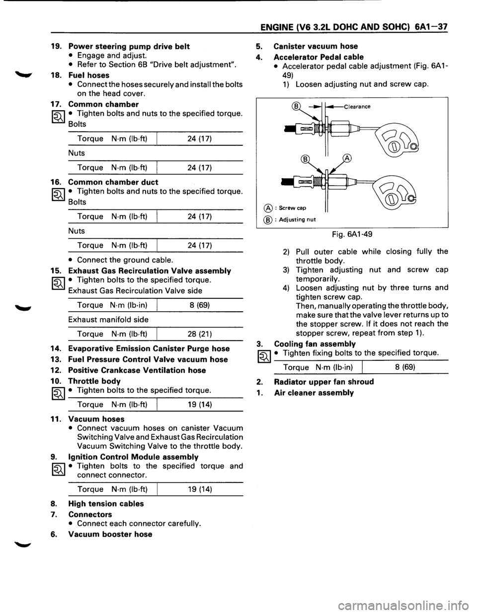
4. Accelerator Pedal cable
• Accelerator pedal cable adjustment (Fig. 6A 1-
49)
1) Loosen adjusting nut and screw cap.
@:Screw cap
@ : Adjusting nut
Fig. 6A1-49
2) Pull outer cable while closing fully the
throttle body.
3) Tighten adjusting nut and screw cap
temporarily.
4) Loosen adjusting nut by three turns and
tighten
screw cap.
Then,
manually operating the throttle body,
make sure that the
valve lever returns up to
the stopper screw. If it does not reach the
stopper screw, repeat
from step 1 ).
3. Cooling fan assembly
~~~· Tighten fixing bolts to the specified torque.
Torque
N·m (lb·in) I 8 (69)
2. Radiator upper fan shroud
1. Air cleaner assembly
Page 602 of 1928
'.:.:.
6A1-44 ENGINE (V6 3.2L DOHC AND SOHC)
1••1 INSTALLATION
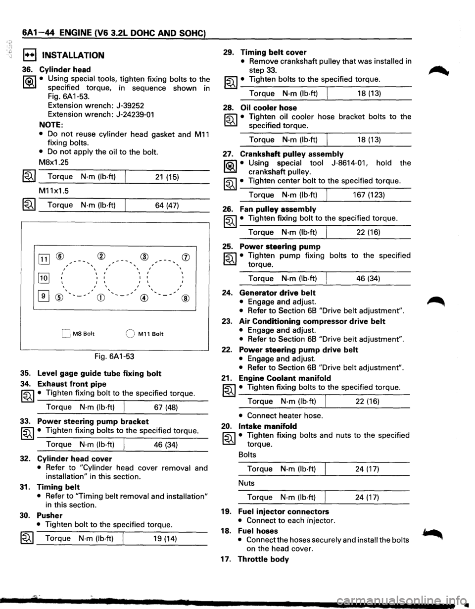
36. Cylinder head
l"i:a\1 • Using special tools, tighten fixing bolts to the
~ specified torque, in sequence shown in
Fig.
6A 1-53.
Extension wrench: J-39252
Extension wrench: J-24239-01
NOTE:
• Do not reuse cylinder head gasket and M11
fixing bolts.
• Do not apply the oil to the bolt.
M8x1.25
1~1 Torque N·m (lb·ft)
M11x1.5
21 (15)
~~~ Torque N·m (lb·ft) 64 (47)
[ill ® ® @ , , , I I I
~
I
I I
I I
I I I
I I
I I I
I I
I
0
' , , ' ' , ' , ' ® '-~ CD @
M8 Bolt QM11Bolt
Fig. 6A1-53
35. Level gage guide tube fixing bolt
34. Exhaust front pipe
' '
, ,
(j)
I
I
I
@
~~~ • Tighten fixing bolt to the specified torque.
Torque
N·m (lb·ft) I 67 (48)
33. Power steering pump bracket
~~~· Tighten fixing bolts to the specified torque.
Torque
N·m (lb·ft) I 46 (34)
32. Cylinder head cover
• Refer to "Cylinder head cover removal and
installation" in this section.
31. Timing belt
• Refer to "Timing belt removal and installation"
in this section.
30. Pusher
• Tighten bolt to the specified torque.
1~1 Torque N·m (lb·ft) I 19 (14)
29. Timing belt cover
• Remove crankshaft pulley that was installed in
step
33.
~~~· Tighten bolts to the specified torque.
Torque
N·m (lb·ft) I 18 (13)
28. Oil cooler hose
~ • Tighten oil cooler hose bracket bolts to the
~ specified torque.
Torque
N·m(lb·ft) I 18(13)
27. Crankshaft pulley assembly
l"i:a\1 • Using special tool J-8614-01, hold the
~ crankshaft pulley.
~~~· Tighten center bolt to the specified torque.
Torque
N·m (lb·ft) I 167 (123)
26. Fan pulley assembly
~~~ • Tighten fixing bolt to the specified torque.
Torque
N·m (lb·ft) I 22 (16)
25. Power steering pump
~ • Tighten pump fixing bolts to the specified
~ torque.
Torque
N-m (lb·ft) 46 (34)
24. Generator drive belt
• Engage and adjust.
• Refer to Section 68 "Drive belt adjustment".
23. Air Conditioning compressor drive belt
• Engage and adjust.
• Refer to Section 68 "Drive belt adjustment".
22. Power steering pump drive belt
• Engage and adjust.
• Refer to Section 68 "Drive belt adjustment".
21. Engine Coolant manifold
~~~· Tighten fixing bolts to the specified torque.
Torque
N·m (lb·ft) J 22 (16)
• Connect heater hose.
20. Intake manifold
~ • Tighten fixing bolts and nuts to the specified
~ torque.
Bolts
Torque N-m (lb·ft) 24 (17)
Nuts
Torque
N-m (lb·ft) 24 (17)
19. Fuel injector connectors
• Connect to each injector.
18. Fuelhoses
• Connect the hoses securely and install the bolts
on the head cover.
17. Throttle body
..
Page 607 of 1928
20. Fuel injector connectors
• Connect to each injector.
19. Fuel hoses
• Connect the hoses securely and install the bolts
on the head cover.
18. Common chamber
• Tighten bolts and nuts to the specified torque.
Bolts
Torque N·m (lb·ft) 24 (17)
Nuts
Torque
N·m (lb·ft) 24 (17)
17. Throttle body
• Connect the engine coolant hose.
16. Common chamber duct
~~~ • Tighten bolts and nuts to the specified torque.
Bolts
Torque N-m (lb·ft) 24 (17)
Nuts
Torque
N·m (lb·ft) 24 (17)
• Connect the ground cable.
15. Exhaust Gas Recirculation Valve assembly
• Tighten bolts to the specified torque.
Exhaust Gas Recirculation
Valve Side
~~~ Torque N·m (lb·in) I 8 (69)
Exhaust Manifold Side
~~~ Torque N·m (lb·ft) 28 (21)
14. Canister vacuum hose
13.
Fuel Pressure Control Valve vacuum hose
12. Positive
Crankcase Ventilation hose
10. Throttle body
~~~· Tighten bolts to the specified torque.
Torque
N·m (lb·ft) I 19 (14)
11. Vacuum hoses
• Connect vacuum hoses on canister Vacuum
Switching Valve and Exhaust Gas Recirculation
Vacuum Switching Valve to the throttle body.
9. Ignition Control Module assembly
~~~· Tighten bolts to the specified torque and
connect connector.
Torque
N-m (lb·ft) 19 (14)
8. High tension cables
7. Connectors
• Connect each connector without fail.
~· 6. Vacuum booster hose
ENGINE (V6 3.2L DOHC AND SOHC) 6A 1-49
5. Canister vacuum hose
4. Accelerator Pedal
cable
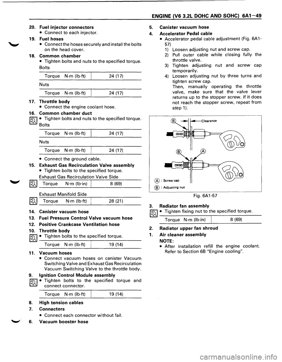
• Accelerator pedal cable adjustment (Fig. 6A 1-
57)
1) Loosen adjusting nut and screw cap.
2) Pull outer cable while closing fully the
throttle valve.
3) Tighten adjusting nut and screw cap
temporarily.
4) Loosen adjusting nut by three turns and
tighten
screw cap.
Then,
manually operating the throttle
valve,
make sure that the valve lever
returns up to the stopper screw. If it does
not reach the stopper screw, repeat from
step 1 ).
@:Screw cap
@ : Adjusting nut
Fig. 6A1-57
3. Radiator fan assembly
~~~· Tighten fixing nut to the specified torque.
Torque
N-m (lb·in) I 8 (69)
2. Radiator upper fan shroud
1. Air cleaner assembly
NOTE:
• After installation refill the engine coolant.
Refer to Section 6B "Engine cooling".
Page 637 of 1928
E!) INSTALLATION
6. Radiator assembly
• Install cushion rubbers on both sides of radia
tor bottom.
• Install radiator assembly with hose, taking
care
not to damage the radiator core with a fan
blade.
5. Bracket
• Support the radiator uppertankwith the bracket
and secure the radiator.
4. Reserve tank hose
3. Fan guide, lower
2. Radiator hose
• Connect inlet hose and outlet hose to the
engine.
1. Oil cooler hose (A/T)
• Connect oil cooler hose for automatic trans-
mission.
• Connect battery ground cable.
• Pour engine coolant.
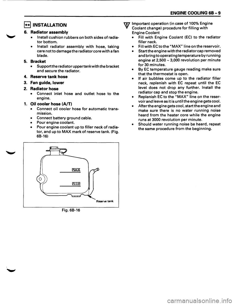
• Pour engine coolant up to filler neck of radia
tor, and up to MAX mark of reserve tank. (Fig.
68-16)
Reserve tank
Fig. 68-16
ENGINE COOLING 68-9
U7 Important operation (in case of 100% Engine
V Coolant change) procedure for filling with
Engine Coolant
• Fill
with Engine Coolant (EC) to the radiator
filler neck.
• Fill with EC to the "MAX" line on the reservoir.
• Start the engine with the radiator cap removed
and bring
to operating temperature by running
engine at
2,500-3,000 revolution per minute
for 30 minutes.
• By EC temperature gauge reading make sure
that the thermostat is open.
• If air bubbles come up to the radiator filler
neck, replenish with EC repeat until the EC
level does not drop any further. Install the
radiator cap and stop the engine.
• Replenish EC to the "MAX" line on the reser
voir and leave as it is until the engine gets cool.
• After the engine gets cool, start the engine and
make sure there is no
water running noise
heard
from the heater core while the engine
runs
at 3000 revolution per minute.
• Should water running noise be heard, repeat
the same procedure from the beginning.
Page 681 of 1928
2,5 3
6 4
CHARGING SYSTEM 603 - 5
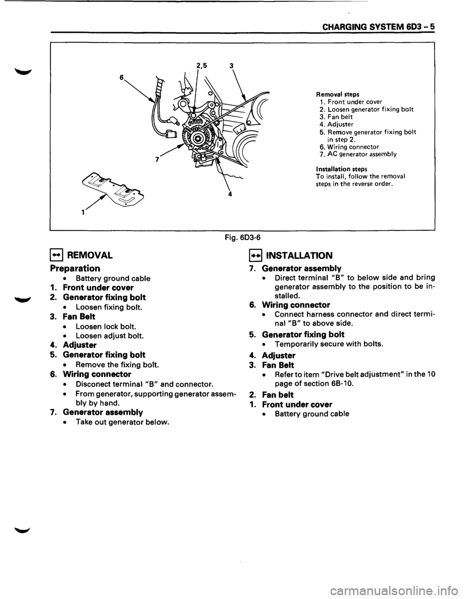
Removal steps
1. Front under cover
2. Loosen generator fixing bolt
3. Fan belt
4. Adjuster
5. Remove generator fixing bolt
in step 2. 6. Wiring connector
7. AC generator assembly
Installation steps To install, follow the removal
steps in
the reverse order.
Fig. 603-6
E] REMOVAL
Preparation
• Battery ground cable
1. Front under cover
2. Generator fixing bolt
• Loosen fixing bolt.
3. Fan Belt
• Loosen lock bolt.
•
Loosen adjust bolt.
4. Adjuster
5. Generator fixing bolt
• Remove the fixing bolt.
6. Wiring connector
• Disconect terminal "B" and connector.
• From generator, supporting generator assem
bly by hand.
7. Generator assembly
• Take out generator below.
EJ INSTALLATION
7. Generator assembly
• Direct terminal "B" to below side and bring
generator assembly to the position to be in
stalled.
6. Wiring connector
• Connect harness connector and direct termi
nal "B" to above side.
5. Generator fixing bolt
• Temporarily secure with bolts.
4. Adjuster
3. Fan Belt
• Refer to item "Drive belt adjustment" in the 10
page of section 6B-1 0.
2. Fan belt
1. Front under cover
• Battery ground cable
Page 684 of 1928
603 - 8 CHARGING SYSTEM
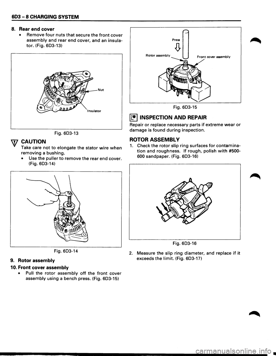
8. Rear end cover
• Remove four nuts that secure the front cover
assembly and rear end cover, and an insula
tor. (Fig. 603-13)
Fig. 603-13
W CAUTION
Take care not to elongate the stator wire when
removing a bushing.
• Use the puller to remove the rear end cover.
(Fig.
603-14)
Fig. 603-14
9. Rotor assembly
10.
Front cover assembly
• Pull the rotor assembly off the front cover
assembly using a bench press. (Fig. 603-15)
Press
Rotor assembly
Fig. 603-15
~ INSPECTION AND REPAIR
Repair or replace necessary parts if extreme wear or
damage is found during inspection.
ROTOR ASSEMBLY
1. Check the rotor slip ring surfaces for contamina
tion and roughness. If rough, polish with #500-
600
sandpaper. (Fig. 603-16)
Fig. 603-16
2. Measure the slip ring diameter, and replace if it
exceeds the limit. (Fig. 603-17)
•
Page 687 of 1928
-
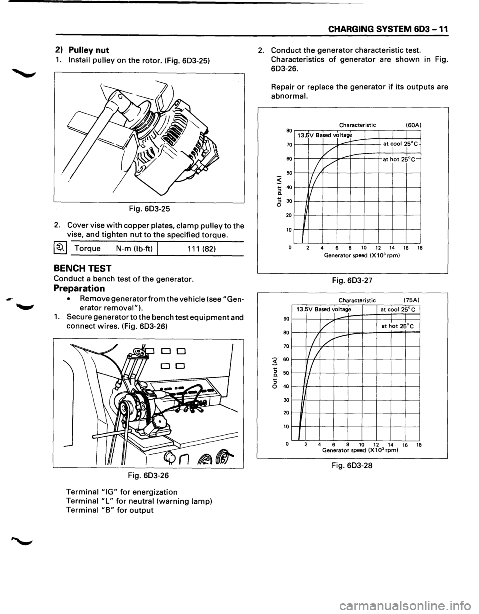
2) Pulley nut
1. Install pulley on the rotor. (Fig. 603-25)
Fig. 603-25
2. Cover vise with copper plates, clamp pulley to the
vise, and tighten nut to the specified torque.
~~~Torque N-m(lb.ft) 111(82)
BENCH TEST
Conduct a bench test of the generator.
Preparation
• Remove generatorfrom the vehicle (see "Gen
erator removal").
1. Secure generator to the bench test equipment and
connect wires. (Fig. 603-26)
DO
DO
Fig. 603-26
Terminal "IG" for energization
Terminal "L" for neutral (warning lamp)
Terminal
"B" for output
CHARGING SYSTEM 603 -11
2. Conduct the generator characteristic test.
Characteristics
of generator are shown in Fig.
603-26.
Repair
or replace the generator if its outputs are
abnormal.
Characteristic (60A) 80 13.5V Based voltage
70
60
50
5 ... 40 "' c. ... 30 "'
......... r-at lool ~5°C
v ,........
/, /
at hot 25°C-
Iff_
f/
0
20
10
J 0 2 4 6 8 10 12 14 16 18
Generator speed (X 103 rpm)
Fig. 603-27
Characteristic (75A)
13.5V Based
voltage at cooi25°C
90
80
70
5 60
...
"' 50 c. ...
v at hot 25°C
I / ~
l/ /
r/
I
"' 0 40
30
20
10
0 2
4 6
8
10 12 14 16
18
Generator speed (X103 rpm)
Fig. 603-28