ECU ISUZU TROOPER 1995 Owner's Guide
[x] Cancel search | Manufacturer: ISUZU, Model Year: 1995, Model line: TROOPER, Model: ISUZU TROOPER 1995Pages: 1928
Page 701 of 1928
......, .., LU
READING DIAGNOSTIC TROUBLE CODES
(Fig. 6E2-1)
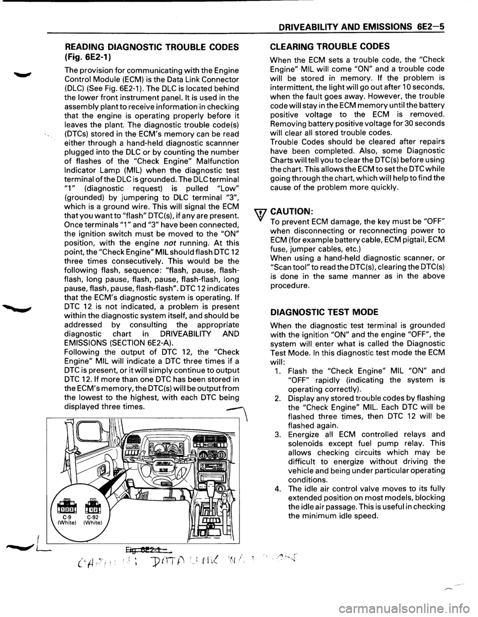
The provision for communicating with the Engine
Control Module (ECM) is the Data Link Connector
(DLC) (See Fig. 6E2-1 ). The DLC is located behind
the
lower front instrument panel. It is used in the
assembly plant
to receive information in checking
that the engine is operating properly before it
leaves the plant. The diagnostic trouble code(s)
(DTCs) stored in the ECM's memory can be read
either through a hand-held diagnostic scannner
plugged into the
DLC or by counting the number
of flashes of the "Check Engine" Malfunction
Indicator Lamp (MIL) when the diagnostic test
terminal
ofthe DLC is grounded. The DLC terminal
"1" (diagnostic request) is pulled "Low"
(grounded) by jumpering to DLC terminal "3",
which is a ground wire. This will signal the ECM
that you want to "flash" DTC(s), if any are present.
Once terminals "1" and "3" have been connected,
the ignition switch
must be moved to the "ON"
position, with the engine not running. At this
point, the
"Check Engine" MIL should flash DTC 12
three times consecutively. This
would be the
following flash, sequence: "flash, pause, flash
flash,
long pause, flash, pause, flash-flash, long
pause, flash, pause, flash-flash". DTC 12 indicates
that the ECM's diagnostic system is operating.
If
DTC 12 is not indicated, a problem is present
within the diagnostic system itself, and should be
addressed
by consulting the appropriate
diagnostic chart in
DRIVEABILITY AND
EMISSIONS (SECTION 6E2-A).
Following the output of DTC 12, the "Check
Engine" MIL
will indicate a DTC three times if a
DTC is present, or it will simply continue to output
DTC 12. If more than one DTC has been stored in
the
ECM's memory, the DTC(s) will be outputfrom
the lowest to the highest, with each DTC being
displayed three times.
--
Eig tU!2-1-...
DRIVEABILITY AND EMISSIONS 6E2-5
CLEARING TROUBLE CODES
When the ECM sets a trouble code, the "Check
Engine" MIL
will come "ON" and a trouble code
will be stored in memory. If the problem is
intermittent, the light
will go out after 10 seconds,
when the fault goes away. However, the trouble
code
will stay in the ECM memory until the battery
positive voltage
to the ECM is removed.
Removing battery positive voltage
for 30 seconds
will clear all stored trouble codes.
Trouble
Codes should be cleared after repairs
have been completed. Also, some Diagnostic
Charts will tell you to clear the DTC(s) before using
the chart. This
allows the ECM tosetthe DTCwhile
going through the chart, which will help to find the
cause
of the problem more quickly.
wcAUTION:
• To prevent ECM damage, the key must be "OFF"
when disconnecting or reconnecting power to
ECM (for example battery cable, ECM pigtail, ECM
fuse, jumper cables, etc.)
When using a hand-held diagnostic scanner,
or
"Scan tool" to read the DTC(s), clearing the DTC(s)
is done in the same manner as in the above
procedure.
DIAGNOSTIC TEST MODE
When the diagnostic test terminal is grounded
with the ignition "ON" and the engine "OFF", the
system
will enter what is called the Diagnostic
Test Mode.
In this diagnostic test mode the ECM
will:
1. Flash the "Check Engine" MIL "ON" and
"OFF" rapidly (indicating the system is
operating correctly).
2. Display any stored trouble codes by flashing
the
"Check Engine" MIL. Each DTC will be
flashed three times, then
DTC 12 will be
flashed again.
3. Energize all ECM controlled relays and
solenoids except
fuel pump relay. This
allows checking circuits which may be
difficult to energize without driving the
vehicle and being under particular operating
conditions.
4. The idle air control valve moves to its fully
extended position on most models, blocking
the
idle air passage. This is useful in checking
the
minimum idle speed.
Page 704 of 1928
6E2-8 DRIVEABILITY AND EMISSIONS
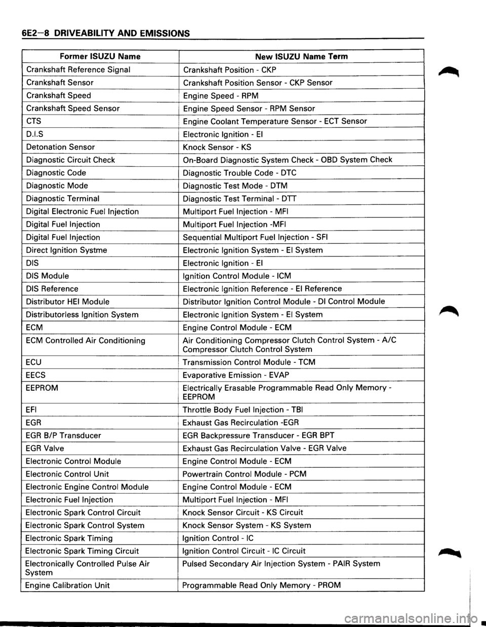
Former ISUZU Name New ISUZU Name Term
Crankshaft Reference Signal Crankshaft Position -CKP
Crankshaft Sensor
Crankshaft Position Sensor -CKP Sensor
Crankshaft Speed
Engine Speed -
RPM
Crankshaft Speed Sensor
Engine Speed Sensor -RPM Sensor
CTS Engine Coolant Temperature Sensor -ECT Sensor
D.I.S Electronic Ignition -El
Detonation Sensor
Knock Sensor-KS
Diagnostic Circuit Check On-Board Diagnostic System Check -OBD System Check
Diagnostic Code Diagnostic Trouble Code -DTC
Diagnostic Mode
Diagnostic Test Mode-DTM
Diagnostic Terminal
Diagnostic Test Terminal -DTT
Digital Electronic
Fuel Injection Multipart Fuel Injection -MFI
Digital Fuel Injection Multipart Fuel Injection -MFI
Digital Fuel Injection Sequential Multipart Fuel Injection -SFI
Direct Ignition Systme Electronic Ignition System -El System
DIS Electronic Ignition -El
DIS Module
Ignition Control Module -ICM
DIS Reference Electronic Ignition Reference -El Reference
Distributor
HEI Module Distributor Ignition Control Module -Dl Control Module
Distributorless Ignition System Electronic Ignition System -
El System
ECM Engine Control Module -ECM
ECM Controlled Air Conditioning Air Conditioning Compressor Clutch Control System -A/C
Compressor Clutch Control System
ECU Transmission Control Module -TCM
EECS Evaporative Emission-EVAP
EEPROM Electrically Erasable Programmable Read Only Memory-
EEPROM
EFI Throttle Body Fuel Injection -TBI
EGR Exhaust Gas Recirculation -EGR
EGR B/P Transducer EGR Backpressure Transducer -EGR BPT
EGR Valve Exhaust Gas Recirculation Valve -EGR Valve
Electronic Control Module Engine Control Module -ECM
Electronic Control Unit Powertrain Control Module -PCM
Electronic Engine Control Module Engine Control Module -ECM
Electronic Fuel Injection Multipart Fuel Injection -MFI
Electronic Spark Control Circuit Knock Sensor Circuit -KS Circuit
Electronic Spark Control System Knock Sensor System -KS System
Electronic Spark Timing Ignition
Control -IC
Electronic Spark Timing Circuit Ignition Control Circuit -IC Circuit
Electronically Controlled Pulse
Air Pulsed Secondary Air Injection System -PAIR System
System
Engine
Calibration Unit Programmable Read Only Memory -PROM
•
Page 707 of 1928
DRIVEABILITY AND EMISSIONS 6E2-11
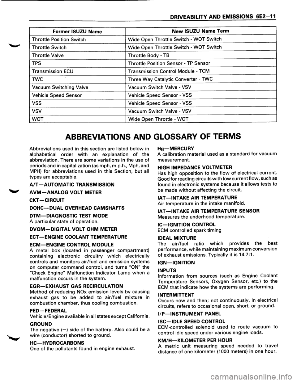
Former ISUZU Name New ISUZU Name Term
Throttle Position Switch Wide Open Throttle Switch -WOT Switch
Throttle Switch
Wide Open Throttle Switch -WOT Switch
Throttle Valve Throttle
Body -TB
TPS Throttle Position Sensor -TP Sensor
Transmission ECU Transmission Control Module -TCM
TWC Three
Way
Catalytic Converter -TWC
Vacuum Switching Valve Vacuum Switch Valve -VSV
Vehicle Speed Sensor Vehicle
Speed Sensor
-VSS
vss Vehicle Speed Sensor -VSS
vsv Vacuum Switch Valve -VSV
WOT
Wide Open Throttle -WOT
ABBREVIATIONS AND GLOSSARY OF TERMS
Abbreviations used in this section are listed below in
alphabetical order with an explanation of the
abbreviation. There are some variations in the use
of
periods and in capitalization (as mph, m.p.h., Mph, and
MPH) for abbreviations used in this Section, but all
types are acceptable.
A/T -AUTOMATIC TRANSMISSION
AVM-ANALOG VOLT METER
CKT -CIRCUIT
DOHC-DUAL OVERHEAD CAMSHAFTS
DTM-DIAGNOSTIC TEST MODE
A particular state of operation.
DVOM-DIGITAL VOLT OHM METER
ECT -ENGINE COOLANT TEMPERATURE
ECM-ENGINE CONTROL MODULE
A metal box (located in passenger compartment)
containing
electronic circuitry which electrically
controls
and monitors air/fuel and emission systems
on
computer command control, and turns "ON" the
"Check Engine"
Malfunction Indicator Lamp when a
malfunction occurs in the system.
EGR-EXHAUST GAS RECIRCULATION
Method of reducing NOx emission levels by causing
exhaust gas
to be added to air/fuel mixture in
combustion chamber, thus
cooling combustion.
FED-FEDERAL
Vehicle/Engine available in all states except California.
GROUND
The negative (-) side of the battery. Also could be a
wire (conductor) shorted to ground.
HC-HVDROCARBONS
One of the pollutants found in engine exhaust.
Hg-MERCURV
A calibration material used as a standard for vacuum
measurement.
HIGH IMPEDANCE VOLTMETER
Has high opposition to the flow of electrical current.
Good
for reading circuits with low currentflow, such as
found in electronic systems because it allows tests to
be made without affecting the circuit.
IAT -INTAKE AIR TEMPERATURE
Air temperature in the intake manifold.
IAT-INTAKE AIR TEMPERATURE SENSOR
Measures the underhood temperature.
IC-IGNITION CONTROL
ECM controlled spark timing
IDEAL MIXTURE
The air/fuel ratio which provides the best
performance,
while maintaining maximum conversion
of exhaust emissions. Typically it is 14.7:1.
IGN-IGNITION
INPUTS
Information from sources (such as Engine Coolant
Temperature Sensors, Oxygen Sensor, etc.) to the
ECM that indicate how the systems are performing.
INTERMITTENT
Occurs now and then; not continuously. In electrical
circuits, refers to occasional open, short, or ground.
liP-INSTRUMENT PANEL
ISC-IDLE SPEED CONTROL
ECM-controlled solenoid used to route vacuum to
control idle speed under various engine loads.
KM/H-KILOMETER PER HOUR
A metric unit measuring speed needed to travel
distance of one kilometer (1 000 meters) in one hour.
Page 753 of 1928
DRIVEABILITY AND EMISSIONS 6E2-57
CHART A-8
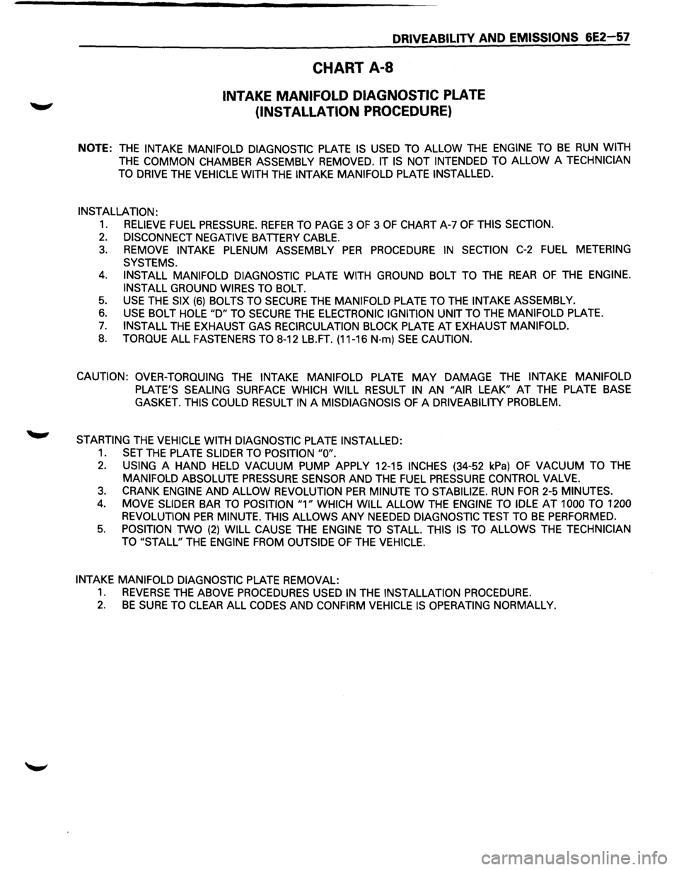
INTAKE MANIFOLD DIAGNOSTIC PLATE
(INSTALLATION PROCEDURE)
NOTE: THE INTAKE MANIFOLD DIAGNOSTIC PLATE IS USED TO ALLOW THE ENGINE TO BE RUN WITH
THE COMMON CHAMBER ASSEMBLY REMOVED. IT IS NOT INTENDED TO ALLOW A TECHNICIAN
TO
DRIVE THE VEHICLE WITH THE INTAKE MANIFOLD PLATE INSTALLED.
INSTALLATION:
1. RELIEVE FUEL PRESSURE. REFER TO PAGE 3 OF 3 OF CHART A-7 OF THIS SECTION.
2. DISCONNECT NEGATIVE BATTERY CABLE.
3. REMOVE INTAKE PLENUM ASSEMBLY PER PROCEDURE IN SECTION C-2 FUEL METERING
SYSTEMS.
4. INSTALL MANIFOLD DIAGNOSTIC PLATE WITH GROUND BOLT TO THE REAR OF THE ENGINE.
INSTALL
GROUND WIRES TO BOLT.
5. USE THE SIX (6) BOLTS TO SECURE THE MANIFOLD PLATE TO THE INTAKE ASSEMBLY.
6. USE BOLT HOLE "D" TO SECURE THE ELECTRONIC IGNITION UNIT TO THE MANIFOLD PLATE.
7. INSTALL THE EXHAUST GAS RECIRCULATION BLOCK PLATE AT EXHAUST MANIFOLD.
8. TORQUE ALL FASTENERS TO 8-12 LB.FT. (11-16 N·m) SEE CAUTION.
CAUTION: OVER-TORQUING
THE INTAKE MANIFOLD PLATE MAY DAMAGE THE INTAKE MANIFOLD
PLATE'S SEALING SURFACE WHICH WILL RESULT IN AN "AIR LEAK" AT THE PLATE BASE
GASKET. THIS COULD RESULT IN A MISDIAGNOSIS OF A DRIVEABILITY PROBLEM.
STARTING THE VEHICLE WITH DIAGNOSTIC PLATE INSTALLED:
1. SET THE PLATE SLIDER TO POSITION "0".
2. USING A HAND HELD VACUUM PUMP APPLY 12-15 INCHES (34-52 kPa) OF VACUUM TO THE
MANIFOLD ABSOLUTE PRESSURE SENSOR AND THE FUEL PRESSURE CONTROL VALVE.
3. CRANK ENGINE AND ALLOW REVOLUTION PER MINUTE TO STABILIZE. RUN FOR 2-5 MINUTES.
4. MOVE SLIDER BAR TO POSITION "1" WHICH WILL ALLOW THE ENGINE TO IDLE AT 1000 TO 1200
REVOLUTION
PER MINUTE. THIS ALLOWS ANY NEEDED DIAGNOSTIC TEST TO BE PERFORMED.
5. POSITION TWO (2) WILL CAUSE THE ENGINE TO STALL. THIS IS TO ALLOWS THE TECHNICIAN
TO "STALL"
THE ENGINE FROM OUTSIDE OF THE VEHICLE.
INTAKE MANIFOLD DIAGNOSTIC
PLATE REMOVAL:
1. REVERSE THE ABOVE PROCEDURES USED IN THE INSTALLATION PROCEDURE.
2. BE SURE TO CLEAR ALL CODES AND CONFIRM VEHICLE IS OPERATING NORMALLY.
Page 806 of 1928
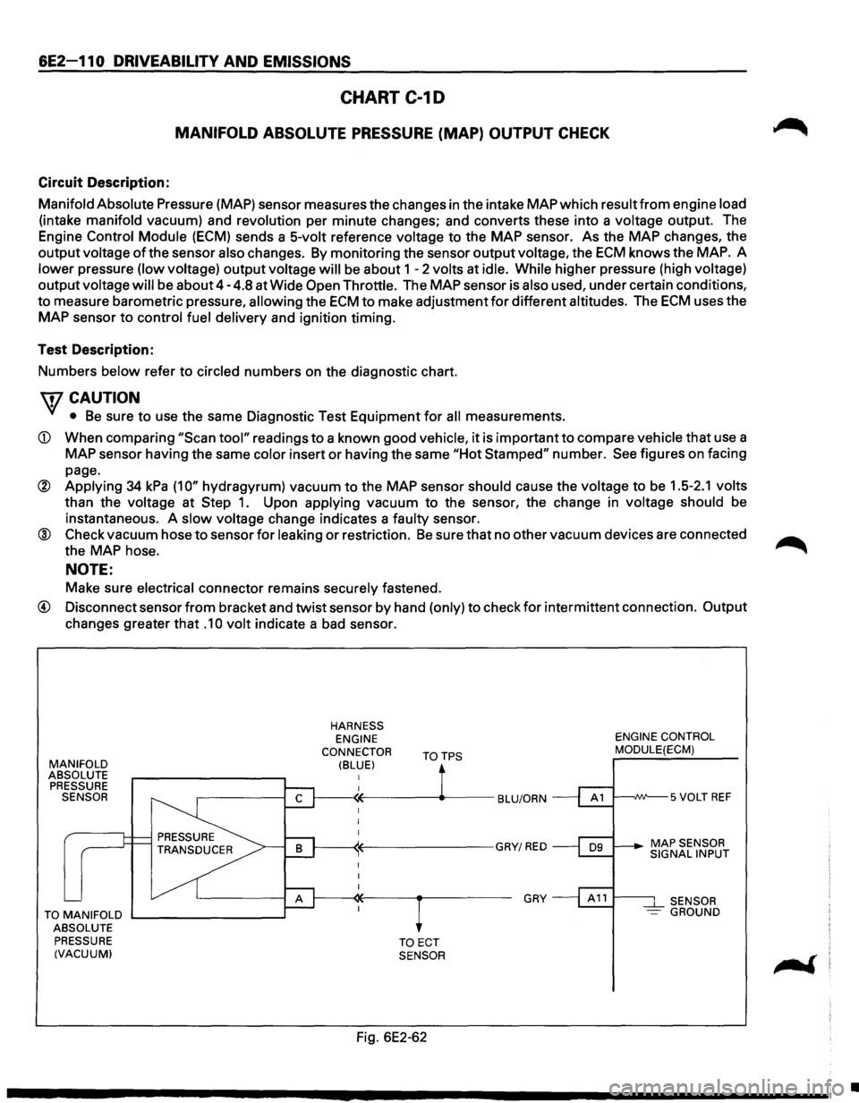
6E2-11 0 DRIVEABILITY AND EMISSIONS
CHART C-10
MANIFOLD ABSOLUTE PRESSURE (MAP) OUTPUT CHECK
Circuit Description:
Manifold Absolute Pressure (MAP) sensor measures the changes in the intake MAP which result
from engine load
(intake manifold vacuum) and revolution per minute changes; and converts these into a voltage output. The
Engine
Control Module (ECM) sends a 5-volt reference voltage to the MAP sensor. As the MAP changes, the
output voltage of the sensor also changes. By monitoring the sensor output voltage, the ECM knows the MAP. A
lower pressure (low voltage)
output voltage will be about 1 - 2 volts at idle. While higher pressure (high voltage)
output voltage
will be about 4-4.8 at Wide Open Throttle. The MAP sensor is also used, under certain conditions,
to measure barometric pressure,
allowing the ECM to make adjustment for different altitudes. The ECM uses the
MAP sensor
to control fuel delivery and ignition timing.
Test Description:
Numbers
below refer to circled numbers on the diagnostic chart.
\fl CAUTION
'(/ • Be sure to use the same Diagnostic Test Equipment for all measurements.
CD When comparing "Scan tool" readings to a known good vehicle, it is important to compare vehicle that use a
MAP sensor having the same color insert
or having the same "Hot Stamped" number. See figures on facing
page.
® Applying 34 kPa (1 0" hydragyrum) vacuum to the MAP sensor should cause the voltage to be 1.5-2.1 volts
than the voltage at
Step 1. Upon applying vacuum to the sensor, the change in voltage should be
instantaneous. A slow voltage change indicates a faulty sensor.
® Check vacuum hose to sensor for leaking or restriction. Be sure that no other vacuum devices are connected ....-...
the MAP hose. ~
NOTE:
Make sure electrical connector remains securely fastened.
@) Disconnect sensor from bracket and twist sensor by hand (only) to check for intermittent connection. Output
changes greater that
.1 0 volt indicate a bad sensor.
MANIFOLD
ABSOLUTE PRESSURE
SENSOR
TO MANIFOLD
ABSOLUTE PRESSURE
(VACUUM)
HARNESS ENGINE
CONNECTOR
(BLUE) TOTPS
TOECT SENSOR
Fig. 6E2-62
GRY
ENGINE CONTROL
MODULE(ECM)
I---...JVV'--5 VOLT
REF
SENSOR -GROUND
•
Page 925 of 1928
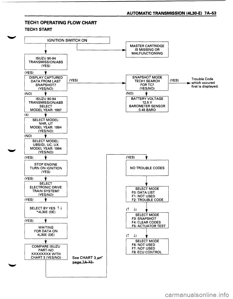
TECH1 OPERATING FLOW CHART
TECH1 START
IGNITION SWITCH ON
ISUZU 90-94
TRANSMISSION/ASS (YES)
(YES)
'
DISPLAY CAPTURED
OAT A FROM LAST (YES) SNAPSHOT?
(YES/NO)
(NO)
'
ISUZU 90-94
TRANSMISSION/ASS SELECT MODEL YEAR: 199?
(4)
'
SELECT MODEL: NHR, UT
MODEL YEAR: 1994 (YES/NO)
(NO)
'
SELECT MODEL: UBS(G), UC, UX
MODEL YEAR: 1994 (YES/NO)
(YES) t
STOP ENGINE TURN ON IGNITION (YES)
(YES)
'
SELECT ELECTRONIC DRIVE
TRAIN SYSTEM? (YES/NO)
(YES)
' SELECT BY YES i ,J.. *4L30E (DE)
(YES)
' WAITING FOR DATA ON 4L30E (DE)
'
COMPARE ISUZU
PART-NO
XXXXXXXX WITH CHART 3 (YES/NO) See CHART 3J)f"'"'"
page 2A +~.
__, -
AUTOMATIC TRANSMISSION (4L30-E) 7 A-53
MASTER CARTRIDGE
IS MISSING OR MALFUNCTIONING
SNAPSHOT MODE
TECH1 SEARCH
FORTC?
(YES/NO)
(NO)
'
BATIERY VOLTAGE 12.5 v BAROMETER SENSOR
0.45 BARO
(YES)
' NO TROUBLE CODES
SELECT MODE FO: OAT A LIST F1: NOT USED F2: TROUBLE CODE
rt ,J..)
SELECT MODE F3: SNAPSHOT F4: CLEAR CODES F5: ACTUATOR TEST
(i ,J..) ,
SELECT MODE F6: NOT USED F7: NOT USED F8: ECU CONTROL
(YES) ...
Trouble Code which occured
first is displayed.
Page 936 of 1928
7 A-64 AUTOMATIC TRANSMISSION (4L30-E)
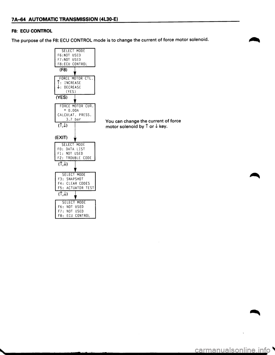
FS: ECU CONTROL
The purpose of the FB: ECU CONTROL mode is to change the current of force motor solenoid.
SELECT MODE F6:NOT USED F7:NOT USED F8:ECU CONTROL
(F8)
FORCE MOTOR CTL.
i: INCREASE .J..: DECREASE (YES)
(YES)
FORCE MOTOR CUR.
* O.OOA CALCULAT. PRESS.
3.7 bar
(i,.J..)
(EXIT) lr
SELECT MODE
FO: DATA LIST Fl: NOT USED F2: TROUBLE CODE
(i,.J..)
SELECT MODE F3: SNAPSHOT F4: CLEAR CODES F5: ACTUATOR TEST
(i,.J..)
SELECT MODE F6: NOT USED
F7: NOT USED F8: ECU CONTROL
You can change the current of force
motor solenoid by i or .J.. key.
Page 1028 of 1928
7A-156 AUTOMATIC TRANSMISSION (4L30-E)
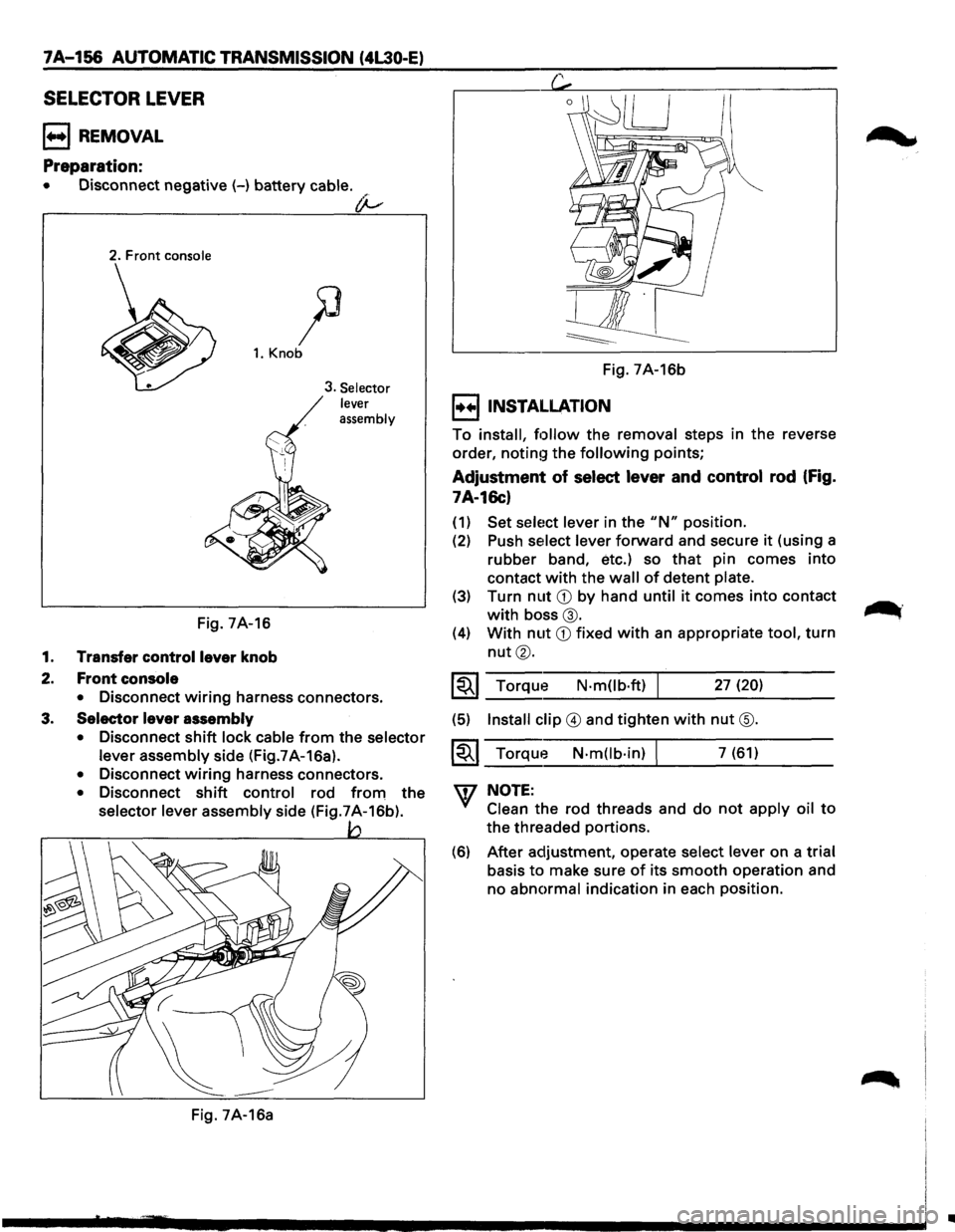
SELECTOR LEVER
B REMOVAL
Preparation:
• Disconnect negative (-) battery cable.
(}-
2. Front console
)3
1. Knob
Fig. 7A-16
1. Transfer control lever knob
2. Front console
3. Selector
lever
assembly
• Disconnect wiring harness connectors.
3. Selector lever assembly
• Disconnect shift lock cable from the selector
lever assembly
side (Fig.7A-16a).
• Disconnect wiring harness connectors.
• Disconnect shift control rod from the
selector lever assembly side (Fig.7A-16b).
Fig. 7A-16a Fig.
7A-16b
I••IINSTALLATION
To install, follow the removal steps in the reverse
order,
notin!~ the following points;
Adjustment of select lever and control rod (Fig.
7A-16c)
(1) Set sele1ct lever in the "N" position.
(2) Push select lever forward and secure it (using a
rubber band, etc.) so that pin comes into
contact with the wall of detent plate.
(3) Turn nut CD by hand until it comes into contact
with boss@.
(4) With nut CD fixed with an appropriate tool, turn
nut®.
~~~ Torque N·mOb·ft) I 27 (20)
(5) Install clip @ and tighten with nut @.
~~~ Torque N·m(lb·in) I 7 (61)
w NOTE:
Clean the rod threads and do not apply oil to
the threaded portions.
(6) After adjustment, operate select lever on a trial
basis to make sure of its smooth operation and
no
abnormal indication in each position.
.......
..._.
II
Page 1098 of 1928
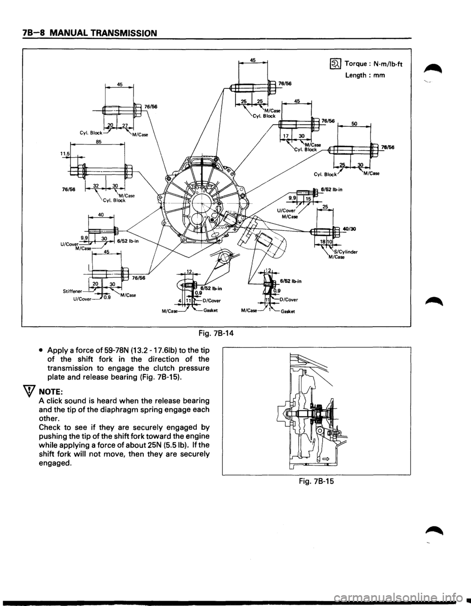
78-8 MANUAL TRANSMISSION
45
Fig. 78-14
• Apply a force of 59-78N (13.2 -17.61b) to the tip
of the shift fork in the direction of the
transmission
to engage the clutch pressure
plate and release bearing (Fig. 78-15).
W NOTE:
A click sound is heard when the release bearing
and the tip
of the diaphragm spring engage each
other.
Check
to see if they are securely engaged by
pushing the tip of the shift fork toward the engine
while applying a force
of about 25N (5.5 I b). If the
shift fork
will not move, then they are securely
engaged.
45 ~ Torque : N·m/lb·ft
Length: mm
Fig. 78-15
..
Page 1196 of 1928
8-6 CHASSIS ELECTRICAL
SPLICING WIRE
1. Open the Harness
If the harness is taped, remove the tape. To avoid wire
insulation damage, use a sewing "seam ripper"
{available from sewing supply stores) to cut open the
harness.
If the harness has a black plastic conduit, simply pull
out the desired wire.
2. Cut the wire
Begin by cutting as little wire off the harness as
possible. You
may need the extra length of wire later
if you decide to cut more wire off to change the
location
of a splice. You may have to adjust splice
locations
to make certain that each splice is at least
1-1/2" {40 mm) away from other splices, harness
branches,
or connectors.
3. Strip the insulation
When replacing a wire, use a wire of the same size as
the original wire. Check the stripped wire for nicks or
cut stands. If the wire is damaged, repeat the proce
dure on a new section of wire. The two stripped wire
ends should be equal in length.
4. Crimp the Wires
Select the proper clip to secure the splice. To deter
mine the proper clip size for the wire being spliced,
follow the directions included with your clips. Select
the correct anvil on the crimper.
{On most crimpers
your choice is limited to either a small or large anvil.)
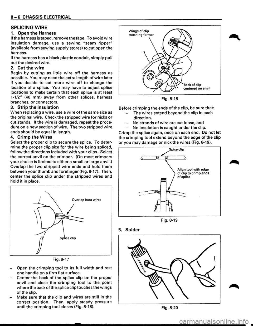
Overlap the two stripped wire ends and hold them
between your thumb and forefinger {Fig. 8-17). Then,
center the splice clip under
the stripped wires and
hold
it in place.
Overlap bare wires
Fig. 8-17
-
Open the crimping tool to its full width and rest
one handle on a
firm flat surface.
- Center
the back of the splice clip on the proper
anvil and close the
crimping tool to the point
where the backofthe splice clip touches the wings
of the clip.
Make sure
that the clip and wires are still in the
correct position. Then,
apply steady pressure
until
the crimping tool closes {Fig. 8-18). Fig.
8-18
Before
crimping the ends ofthe clip, be sure that:
The wires extend beyond
the clip in each
direction.
No strands of wire are cut loose, and
No insulation is caught under
the clip.
Crimp the splice again, once on each end. Do
not let
the crimping tool extend beyond the edge of the clip
or you may damage or nick the wires (Fig. 8-19).
5. Solder
Spice clip
6:~
Fig. 8-19
Align tool with edge of clip to crimp ends of splice
Fig. 8-20