ECU ISUZU TROOPER 1995 Workshop Manual
[x] Cancel search | Manufacturer: ISUZU, Model Year: 1995, Model line: TROOPER, Model: ISUZU TROOPER 1995Pages: 1928
Page 49 of 1928
HEATING AND VENTILATION 1A-19
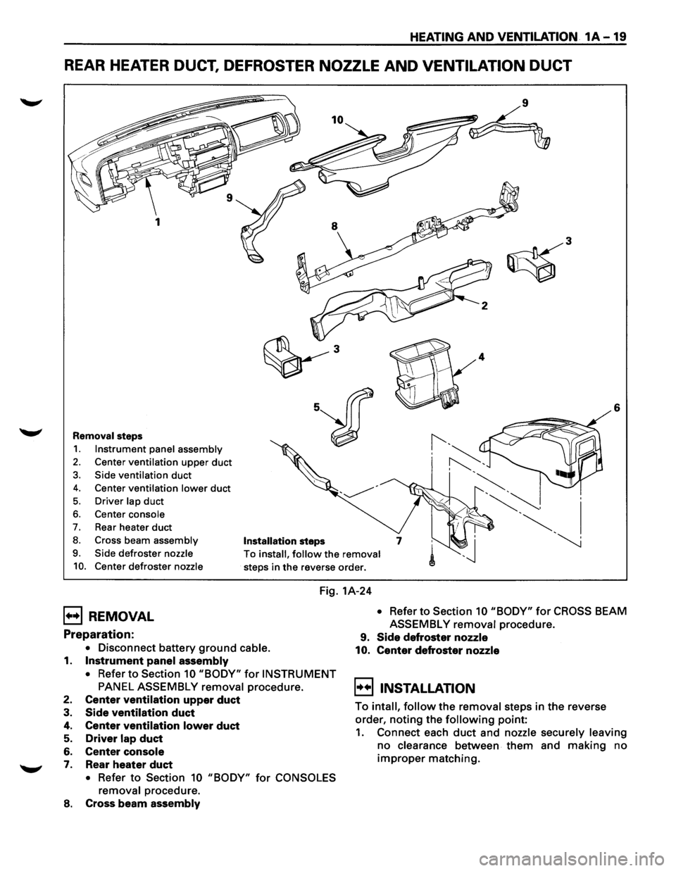
REAR HEATER DUCT, DEFROSTER NOZZLE AND VENTILATION DUCT
6
Removal steps
1. Instrument panel assembly
2. Center ventilation upper duct
3. Side ventilation duct
4. Center ventilation lower duct
5. Driver lap duct
6. Center console
7. Rear heater duct
8. Cross beam assembly Installation steps
9. Side defroster nozzle
10. Center defroster nozzle
To install, follow the removal
steps in the reverse order.
Fig. 1A-24
B REMOVAL
Preparation:
• Disconnect battery ground cable.
1. Instrument panel assembly
• Refer to Section 10 "BODY" for INSTRUMENT
PANEL ASSEMBLY removal procedure.
2. Center ventilation upper duct
3. Side ventilation duct
4. Center ventilation lower duct
5. Driver lap duct
6. Center console
7. Rear heater duct
• Refer to Section 10 "BODY" for CONSOLES
removal
procedure.
8. Cross beam assembly
• Refer to Section 10 "BODY" for CROSS BEAM
ASSEMBLY
removal procedure.
9. Side defroster nozzle
10. Center defroster nozzle
~!!) INSTALLATION
To intall, follow the removal steps in the reverse
order,
noting the following point:
1. Connect each duct and nozzle securely leaving
no clearance between them and making no
improper matching.
Page 63 of 1928
DIAGNOSIS
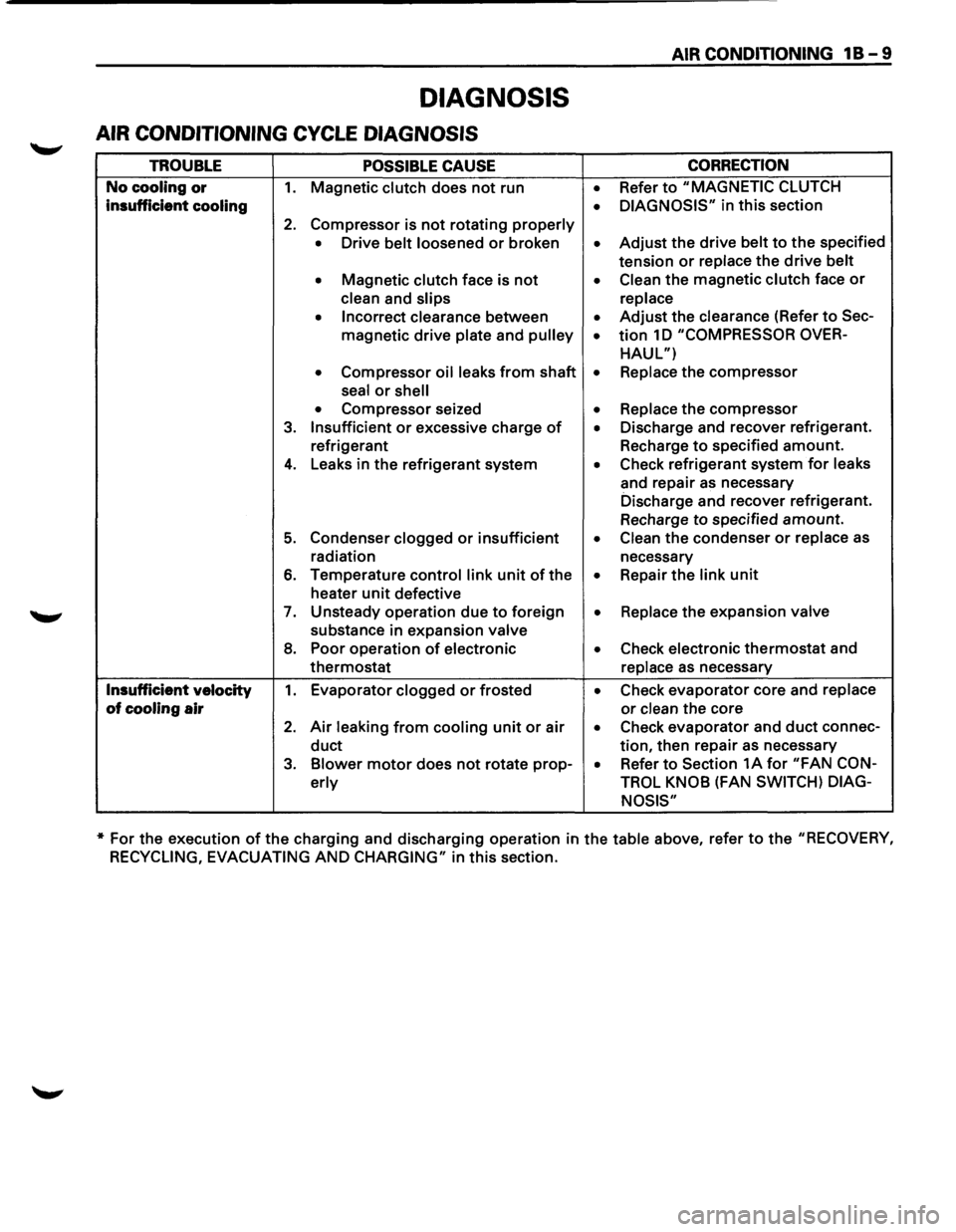
AIR CONDITIONING CYCLE DIAGNOSIS
TROUBLE POSSIBLE CAUSE
No cooling or 1. Magnetic clutch does not run
insufficient cooling
2. Compressor is not rotating properly
• Drive belt loosened or broken
• Magnetic clutch face is not
clean and slips
• Incorrect clearance between
magnetic
drive plate and pulley
• Compressor oil leaks from shaft
seal
or shell
• Compressor seized
3. Insufficient or excessive charge of
refrigerant
4. Leaks in the refrigerant system
5. Condenser clogged or insufficient
radiation
6. Temperature control link unit of the
heater
unit defective
7. Unsteady operation due to foreign
substance in expansion valve
8. Poor operation of electronic
thermostat
Insufficient velocity 1. Evaporator clogged or frosted
of cooling air
2. Air leaking from cooling unit or air
duct
3. Blower motor does not rotate prop-
erly
AIR CONDITIONING 1 B - 9
CORRECTION
• Refer to "MAGNETIC CLUTCH
• DIAGNOSIS" in this section
• Adjust the drive belt to the specified
tension
or replace the drive belt
• Clean the magnetic clutch face or
replace
• Adjust the clearance (Refer to Sec-
• tion 1 D "COMPRESSOR OVER-
HAUL")
• Replace the compressor
• Replace the compressor
• Discharge and recover refrigerant.
Recharge
to specified amount.
• Check refrigerant system for leaks
and repair
as necessary
Discharge and recover refrigerant.
Recharge
to specified amount.
• Clean the condenser or replace as
necessary
• Repair the link unit
• Replace the expansion valve
• Check electronic thermostat and
replace
as necessary
• Check evaporator core and replace
or clean the core
• Check evaporator and duct connec-
tion, then repair as necessary
• Refer to Section 1A for "FAN CON-
TROL KNOB
(FAN SWITCH) DIAG-
NOSIS"
* For the execution of the charging and discharging operation in the table above, refer to the "RECOVERY,
RECYCLING, EVACUATING
AND CHARGING" in this section.
Page 73 of 1928
AIR CONDITIONING 1 B -19
ON-VEHICLE SERVICE
GENERAL REPAIR PROCEDURE
Precautions for Replacement or Repair of Air
Conditioning Parts
There are certain procedures, practices and pre
cautions
that should be followed when servicing air
conditioning systems:
• Keep your work area clean.
•
Always wear safety goggle and protective gloves
when working on refrigerant systems.
• Beware of the danger of carbon monoxide fumes
caused by running the engine.
• Beware of discharged refrigerant in enclosed or
improperly ventilated garages.
• Always disconnect the negative battery cable and
discharge and recover the refrigerant
whenever
repairing the air conditioning system.
• When discharging and recovering the refrigerant,
do not allow refrigerant to discharge too fast; it
will draw compressor oil out of the system.
• Keep moisture and contaminants out of the sys
tem.
When disconnecting or removing any lines
or parts, use plugs or caps to close the fittings
immediately.
Never remove the caps or plugs until the lines or
parts are reconnected or installed.
•
When disconnecting or reconnecting the lines,
use
two wrenches to support the line fitting, to
prevent from twisting or other damage.
• Always install new 0-rings whenever a connec
tion is disassembled.
• Before connecting any hoses or lines, apply new
specified compressor oil to the 0-rings.
• When removing and replacing any parts which
require discharging the refrigerant circuit, the
operations described in
this section must be per
formed in the following sequence:
1. Use the J-39500 (ACR4
: HFC-134a Refrigerant
Recovery/Recycling/Recharging/System)
or
equivalent to thoroughly discharge and re
cover
the refrigerant.
2. Remove and replace the defective part.
3.
After evacuation, charge the air conditioning
system and check for leaks.
Repair of Refrigerant Leaks
Refrigerant Line Connections
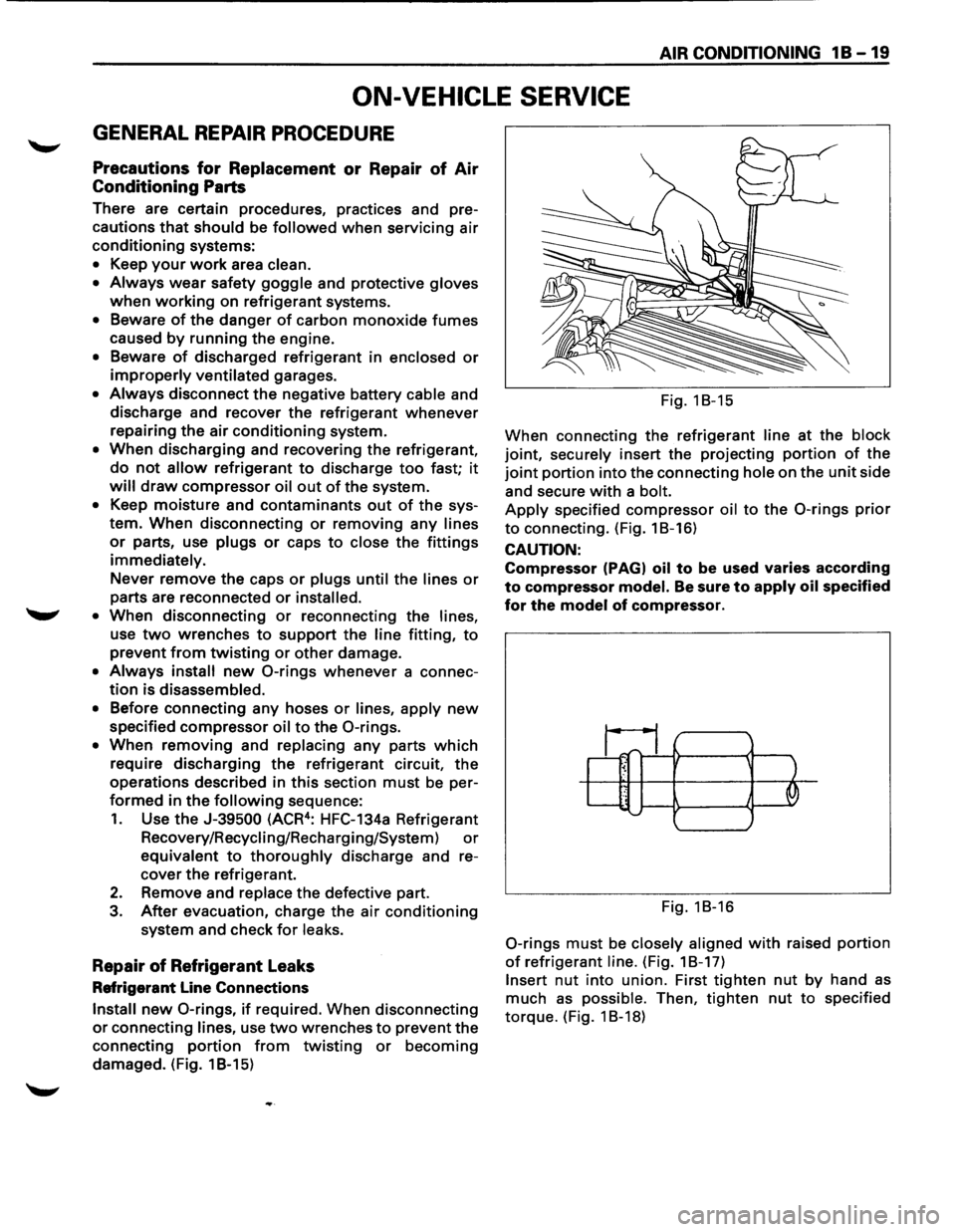
Install new 0-rings, if required. When disconnecting
or connecting lines, use two wrenches to prevent the
connecting
portion from twisting or becoming
damaged. (Fig. 1 B-15) Fig.
18-15
When connecting the refrigerant
line at the block
joint, securely insert the projecting portion of the
joint portion into the connecting hole on the unit side
and secure
with a bolt.
Apply specified compressor oil to the 0-rings prior
to connecting. (Fig. 18-16)
CAUTION:
Compressor (PAGI oil to be used varies according
to compressor model. Be sure to apply oil specified
for the model of compressor.
~1;1_ ~ ' .. J '--......
Fig. 18-16
0-rings must be closely aligned with raised portion
of refrigerant line. (Fig. 18-17)
Insert nut into union. First tighten nut by hand as
much as possible. Then, tighten nut to specified
torque. (Fig. 1 8-18)
Page 142 of 1928
381 - 4 POWER STEERING GEAR AND PUMP
ON-VEHICLE SERVICE
MAINTENANCE
The hydraulic system should be kept clean and fluid
level in the reservoir should be checked at regular
intervals
and fluid added when required. Refer to
"MAINTENANCE AND LUBRICATION" in section OB
ofthe manual for type offluid to be used and intervals
for filling.
If the system contains some dirt, flush it as detailed
later
in this section. If it is exceptionally dirty, both the
pump and the gear must be completely disassembled
before further usage.
All tubes, hoses, and fittings should be inspected for
leakage at regular intervals. Fittings must be tight.
Make sure the clips, clamps and supporting tubes and
hoses are in
place and properly secured.
Power steering hoses and lines must not be twisted,
kinked or tightly bent. Air in the system will cause
spongy action and noisy operation. When a hose is
disconnected
or when fluid is lost, for any reason, the
system must be bled after refilling. Refer to "Bleeding
the Power Steering System" in this section.
FLUID LEVEL
1. Run the engine until the power steering fluid
reaches normal operating temperature, about
55°C (130°F), then shut the engine off.
2. Check the level of fluid in the reservoir.
3. If the fluid level is low, add power steering fluid
as specified in "MAINTENANCE AND LUBRI
CATION" in Section OB to the proper level and
install the receiver cap.
4. When checking the fluid level after the steering
system has been serviced,
air must be bled from
the system. Refer to "Bleeding the Power
Steering
System" in this section.
BLEEDING THE POWER STEERING
SYSTEM
When a power steering pump or gear has been
installed, or an oil line has been disconnected, the air
that has entered the system must be bled out before
the vehicle is operated. If air is allowed to remain in
the power steering fluid system, noisy and
unsatisfactory operation of the system may result.
BLEEDING PROCEDURE
When bleeding the system, and any time fluid is
added
to the power steering system, be sure to use
only power steering fluid as specified in
"MAINTENANCE AND LUBRICATION" in section OB.
1. Fill the pump fluid reservoir to the proper level
and let the fluid settle for at least two minutes.
2. Start the engine and let it run for a few seconds.
Do
not turn the steering wheel. Then turn the
engine off.
3. Add fluid if necessary.
4. Repeat the above procedure until the fluid level
remains constant after running the engine.
5. Raise the front end of the vehicle so that the
wheels are off the ground.
6. Start the engine. Slowly turn the steering wheel
right and left, lightly contacting the wheel stops.
7. Add power steering fluid if necessary.
8. Lower the vehicle and turn the steering wheel
slowly from lock to lock.
9. Stop the engine. Check the fluid level and refill
as required.
10.
If the fluid is extremely foamy, allow the vehicle
to stand a few minutes and repeat the above
procedure.
~ INSPECT
• Belt for tightness.
• Pulley for looseness or damage. The pulley
should not wobble with the engine running.
• Hoses so they are not touching any other parts
of the vehicle.
• Fluid level
and fill to the proper level.
FLUSHING THE POWER STEERING
SYSTEM
1. Raise the front end of the vehicle off the ground
until the wheels are free to turn.
2. Remove the fluid return line at the pump inlet
connector and plug the connector port on the
pump.
Position the line toward a large container to
catch the draining fluid.
3. While running the engine at idle, fill the reservoir
with new power steering fluid. Turn the steering
wheel in both directions. DO NOT contact wheel
stops or hold the wheel in a corner, or fluid will
stop and the pump will be in pressure relief mode.
A sudden
overflow from the reservoir may
develop if the wheel is held at a stop.
4. Install all the lines and hoses. Fill the system with
new power steering fluid and bleed the system
as described in "Bleeding The Power Steering
System". Operate the engine for about 15
minutes.
Remove the
pump return line at the pump inlet
and plug the connection on the pump. While
refilling the reservoir, check the draining fluid for
contamination. If foreign material is still evident,
replace all lines, disassemble and clean or replace
the power steering system components. Do not
re-use any drained power steering fluid.
~
~
Page 165 of 1928
FRONT SUSPENSION 3C-1
SECTION 3C
FRONT SUSPENSION
'\f CAUTION:
When fasteners are removed, always reinstall them at the same location from which they were removed.
If a fastener needs to be replaced, use the correct part number fastener for that application. If the correct
part
number fastener is not available, a fastener of equal size and strength (or stronger) may be used.
Fasteners
that are not reused, and those requiring thread locking compound, will be called out. The correct
torque value must be used when installing fasteners that require it. If the above conditions are not
followed, parts or system damage could result.
Refer to section 3A in this manual for the wheel alignment procedure.
CONTENTS
General Description .. .. .. .. .. .. .. .. .. .. .. .. .. .. . 3C- 1
On-Vehicle Service .............................. 3C-3
Shock Absorber . . . . . . . . . . . . . . . . . . . . . . . . . . . . . . . 3C-3
Stabilizer Bar . .. .. . .. .. ..
.. . .. .. . .. .. .. . .. .. .. . 3C- 4
Torsion Bar
.................................... 3C-5
Knuckle . .
. . . . . . . . . . . . . . . . . . . . . . . . . . . . . . . . . . . . . . 3C-7
Upper
Control Arm ........................... 3C-10
Lower Control Arm ........................... 3C-13
Upper Ball Joint ............................... 3C- 16
Lower
Ball Joint ............................... 3C-18
Main Data and Specifications.................. 3C-20
General
Specifications . .
. . . . . . . . . . . . . . . . . . . . . 3C-
20
Torque Specifications ........................ 3C-21
Special Tools ..................................... 3C-22
GENERAL DESCRIPTION
The front suspension is designed to allow each wheel
to compensate for changes in the road surface level
without greatly affecting the opposite wheel. Each
wheel is independently connected to the frame by a
steering
knuckle, ball joint assemblies, and upper and
lower control arms. The front wheels are held in
proper relationship to each other by two outer track
rods
which are connected to steering arms on the
knuckles and to a center track rod.
All models have a front suspension system consisting
of control arms, stabilizer bar, shock absorber and a
torsion bar. The front end of the torsion bar is
attached
to the lower control arm. The rear of the
torsion bar is mounted into a height control arm at the
crossmember. Vehicle trim height is controlled by
adjusting this arm.
Shock absorbers are
mounted between the brackets
on the
frame and the lower control arms. The lower
portion of each shock absorber is attached to the
lower control arm by a bolt and nut. The upper portion
of each shock absorber extends through a frame
bracket and is secured with two rubber bushings,
three retainers and a nut.
Ball joint assemblies are bolted to the outer end of the
upper and lower control arm and are attached to the
steering
knuckle by nuts and cotter pins.
The
inner ends of the upper control arm have pressed
in bushings.
Bolts, passing through the bushing,
attach the control arm to the frame. The inner ends of
the lower control arm are attached to the frame by
bolts passing through the bushings, which are
pressed in the frame.
Side
roll of the front suspension is controlled by a
spring steel stabilizer bar. It is mounted in rubber
bushings, which are held to the crossmember by
brackets. The ends of the stabilizer bar are connected
to the lower control arms by links.
Page 214 of 1928
![ISUZU TROOPER 1995 Workshop Manual 3F4-4 SUPPLEMENTAL RESTRAINT SYSTEM (SRS) STEERING WHEEL & COLUMN
(b!] INSPECTION AND REPAIR
\f WARNING
THE INFLATOR MODULE SHOULD ALWAYS BE
CARRIED WITH THE URETHANE COVER AWAY
FROM YOUR BODY](/img/61/57183/w960_57183-213.png "ISUZU TROOPER 1995 Workshop Manual 3F4-4 SUPPLEMENTAL RESTRAINT SYSTEM (SRS) STEERING WHEEL & COLUMN
(b!] INSPECTION AND REPAIR
\f WARNING
THE INFLATOR MODULE SHOULD ALWAYS BE
CARRIED WITH THE URETHANE COVER AWAY
FROM YOUR BODY")
3F4-4 SUPPLEMENTAL RESTRAINT SYSTEM (SRS) STEERING WHEEL & COLUMN
(b!] INSPECTION AND REPAIR
\f' WARNING
THE INFLATOR MODULE SHOULD ALWAYS BE
CARRIED WITH THE URETHANE COVER AWAY
FROM YOUR BODY AND SHOULD ALWAYS BE
LAID ON A FLAT SURFACE WITH THE URE
THANE SIDE UP. THIS IS NECESSARY BE
CAUSE A FREE SPACE IS PROVIDED TO ALLOW
THE AIR CUSHION TO EXPAND IN THE UN
LIKELYEVENT OF ACCIDENTAL DEPLOYMENT.
OTHERWISE, PERSONAL INJURY
MAY RESULT
(FIG. 3F4-5).
Fig. 3F4-5
The
Inflator module consists of a cover, air bag,
inflator, and retainer.
Inspect the Inflator module
mainly for the following:
1) Check for holes, cracks, severe blemishes and
deformation on the cover.
2) Check that the retainer is not deformed.
3) Check for defects such as damage and breakage in
the lead
wire ofthe squib.
If an abnormality is found as the result of the in
spection, replace the
Inflator module with a new one.
l·u·IINSTALLATION
3. Inflator module
2. Module connector
• Support the module and carefully connectthe
module connector.
NOTE:
Pass the lead wire through the tabs on the plastic
cover (wire protector)
of inflator to prevent lead
wire
from being pinched.
1. Fixing bolt
• Secure the module with one bolt to relieve
weight on the connector wire.
• Tighten bolts to specified sequence as figure
(Fig. 3F4-6).
Torque
N·m(lb·in.) 8 (69)
• Connect the yellow 3way SRS connector
located under the steering column.
• Connect the battery .. _. terminal cable.
• Set ignition to "ON" while watching warning light.
Light should flash 7 times and then go off.
If lamp
does
not operate correctly, refer to Section 9J.
Fig. 3F4-6
STEERING WHEEL REPLACEMENT
\f' CAUTION:
Once the steering column is removed from the
vehicle, the
column is extremely susceptible to
damage. Dropping the column assembly on its
end
could collapse the steering shaft or loosen
the
slide block which maintains column rigidity.
Leaning on the column assembly could cause the
jacket
to bend or deform. Any of the above
damage could
impair the column's collapsible
design. If it is necessary to remove the steering
wheel, use
only the specified steering wheel
puller.
Under no conditions should the end of the
shaft be hammered upon,
as hammering could
loosen
slide block which maintains column
rigidity.
•
Page 216 of 1928
3F4-6 SUPPLEMENTAL RESTRAINT SYSTEM ISRSI STEERING WHEEL & COLUMN
2. Horn lead
3. Steering wheel fixing nut
4. Steering wheel
• Apply a setting mark across the steering
wheel and shaft so parts can be reassembled
in
their original position (Fig. 3F4-10)
•
Use special tool. Remove the steering wheel.
Move the tires to the straight ahead position
before removing
the steering wheel (Fig. 3F4-
11 ).
1®.1 Steering wheel remover: J-29752
Setting mark
Fig. 3F4-10
Fig. 3F4-11
"fCAUTION:
Never apply force to the steering wheel in
direction
ofthe shaft by using a hammer or other
impacttools in an attemptto remove the steering
wheel. The steering shaft is designed as an
energy absorbing unit.
B INSTALLATION
4. Steering wheel
• Align the setting marks made when re
moving.
"f CAUTION:
3.
~
2.
1.
~
Never apply force to the steering wheel in
direction
of the shaft by using a hammer or other
impacttools in an attemptto remove the steering
wheel. The steering shaft is designed as an
energy absorbing unit.
Steering wheel fixing nut
• Tighten the steering wheel fixing nut to the
specified torque.
Torque
N-m (lb·ft) 34 (25)
Horn
lead
Inflator module
• Support the module and carefully connect the
module connector.
NOTE:
Pass the lead wire through the tabs on the plastic
cover (wire protector) of inflator to prevent lead
wire from being pinches.
• Secure the module with one bolt to relieve
weight on the connector wire.
• Tighten bolts to specified sequence as figure
(Fig. 3F4-12).
Torque
N·m (lb-in) 8 (69)
• Connect the yellow 3way SRS connector located
under the steering column.
• Connect the battery"-" terminal cable.
• Set ignition to "ON• while watching warning light.
Light
should flash 7 times and then go off. If lamp
does not operate correctly, refer to Section 9J.
Fig. 3F4-12
~
•
Page 219 of 1928
SUPPLEMENTAL RESTRAINT SYSTEM (SRS) STEERING WHEEL & COLUMN 3F4-9
B INSTALLATION
6. Combination switch and SRS coil assembly
•
After installation of combination switch as
sembly, connect the combination switch
wiring harness connector and the SRS 3way
connector located under the steering column.
•
Turn the SRS coil clockwise to full, return
about 3
turns and align the neutral mark
(Fig.3F4-20).
Alignment mark
Fig. 3F4-20
WcAUTION:
When turning the SRS coil clockwise to full, stop
turning if resistance is felt. Forced further turning
may damage to the cable in the SRS coil.
5. Steering column cover
• When installing the steering column cover, be
sure
to wire (through each harness) as
illustrated so that the harnesses starter
switch,
combination switch and SRS coil may
not catch wiring (Fig. 3F4-21 ).
Starter switch
harness
Combination switch harness
Inflator module harness
Fig. 3F4-21
4. Steering wheel
• Align the setting marks made when re
moving.
W CAUTION:
Never apply force to the steering wheel in
direction
of the shaft by using a hammer or other
impact tools in an attempt to remove the steering
wheel. The steering shaft is designed as an
energy absorbing unit.
• Tighten the steering wheel fixing nut to the
specified torque.
Torque
N·m (lb-ft) 34 (25)
3. SRS module
• Support the module and carefully connect the
module connector.
NOTE:
Pass the lead wire through the tabs on the plastic
cover (wire protector) of inflator to prevent lead
wire from being pinched.
• Secure the module with one bolt to relieve
weight on the connector wire.
• Tighten bolts to specified sequence as figure
(Fig. 3F4-22).
Torque
N·m (lb·in) 8 (69)
2. Steering lower cover
• Install the engine hood opening lever.
1. Front console assembly
• Install
the transmission (for MfT) and transfer
control lever knob.
• Install the wiring harness connectors.
• Connect the battery "-"terminal cable.
• Set
ignition to ·oN" while watching warning light.
•
Light should flash 7 times and then go off. If lamp
does not operate correctly, refer to Section 9J.
Fig. 3F4-22
Page 222 of 1928
3F4 -12 SUPPLEMENTAL RESTRAINT SYSTEM (SRS) STEERING WHEEL & COLUMN
Alignment mark
Fig. 3F4-28
\fCAUTION:
When turning the SRS coil clockwise to full, stop
turning if resistance is felt. Forced further turning
may damage to the cable in the SRS coil.
5. Steering column cover
• When installing the steering column cover, be
sure
to wire (through each harness) as
illustrated so that the harnesses starter
switch,
combination switch and SRS coil may
not catch wiring (Fig. 3F4-29).
Starter switch
harness
Combination
switch harness
Inflator module
harness
4. Steering wheel
Fig. 3F4-29
• Align the setting marks made when re
moving.
\fCAUTION:
Never apply force to the steering wheel in
direction
of the shaft by using a hammer or other
impacttools in an attemptto remove the steering
wheel. The steering shaft is designed as an
energy absorbing unit.
• Tighten the steering wheel fixing nut to the
specified torque.
~~~ Torque N·m (lb-ft) 34 (25)
3. Inflator module
• Support the module and carefully connect the
module connector.
NOTE:
Pass the lead wire through the tabs on the plastic
cover (wire protector) of inflator to prevent lead
wire from being pinched.
• Secure the module with one bolt to relieve
weight on the connector wire.
• Tighten fixing bolts to specified sequence as
figure (Fig. 3F4-30).
1~1 Torque N·m (lb-in) 8 (69)
Fig.
3F4-30
2. Steering lower cover
• Install the engine hood opening lever.
1. Front console assembly
• Connect the wiring harness connectors.
• Install the transmission (for Mff) and transfer
control lever knob.
• Connect the yellow 3way SRS connector located
under the steering column.
• Connect the battery"-" terminal cable.
SYSTEM INSPECTION
• Set ignition to "ON" while watching warning
light.
•
Light should flash 7 times and then go off. If
lamp does not operate correctly, refer to
Section 9J.
Page 226 of 1928
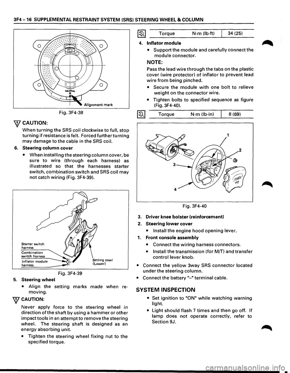
3F4-16 SUPPLEMENTAL RESTRAINT SYSTEM (SRS) STEERING WHEEL & COLUMN
Alignment mark
Fig. 3F4-38
\fCAUTION:
When turning the SRS coil clockwise to full, stop
turning if resistance is felt. Forced furtherturning
may damage to the cable in the SRS coil.
6. Steering column cover
• When installing the steering column cover, be
sure
to wire (through each harness) as
illustrated so that the harnesses starter
switch,
combination switch and SRS coil may
not catch wiring (Fig. 3F4-39).
Starter switch
harness
Combination switch harness
Inflator module harness
5. Steering wheel
Fig. 3F4-39
• Align the setting marks made when re
moving.
WCAUTION:
Never apply force to the steering wheel in
direction
ofthe shaft by using a hammer or other
impacttools in an attempt to remove the steering
wheel. The steering
shaft is designed as an
energy absorbing unit.
• Tighten the steering wheel fixing nut to the
specified torque. Torque
N·m (lb·ftl 34
(25)
4. Inflator module
• Support the module and carefully connect the
module connector.
NOTE:
Pass the lead wire through the tabs on the plastic
cover (wire protector) of inflator to prevent lead
wire from being pinched.
• Secure the module with one bolt to relieve
weight on the connector wire.
• Tighten bolts to specified sequence as figure
(Fig. 3F4-40).
Torque
N·m (lb-in) 8 (69)
Fig. 3F4-40
3. Driver knee bolster (reinforcement)
2. Steering lower cover
• Install the engine hood opening lever.
1. Front console assembly
• Connect the wiring harness connectors.
• Install the transmission (for M/T) and transfer
control lever knob.
• Connect the yellow 3way SRS connector located
under the steering column.
• Connect the battery "-"terminal cable.
SYSTEM INSPECTION
• Set ignition to "ON" while watching warning
light.
• Light should flash 7 times and then go off. If
lamp does not operate correctly, refer to
Section 9J.
•