ESP ISUZU TROOPER 1995 User Guide
[x] Cancel search | Manufacturer: ISUZU, Model Year: 1995, Model line: TROOPER, Model: ISUZU TROOPER 1995Pages: 1928
Page 616 of 1928
,): .. • T·
6A 1-58 ENGINE (V6 3.2L DOHC AND SOHC)
EJ REMOVAL
1. Engine assembly
• See "Engine Assembly
Removal and Instal-
lation".
2. Crankshaft pulley
3. Timing belt cover
4. Timing belt
5. Oil pan
6. Oil pipe and rubber ring
7. Oil strainer and rubber ring
8. Oil pump assembly
9. Crankcase side bolts
10.
Oil gallery
11. Flywheel
12.
Rear oil seal retainers
13.
Connecting rod caps
14.
Crankshaft main bearing caps
15.
Crankshaft and main bearings
1•+1 INSTALLATION
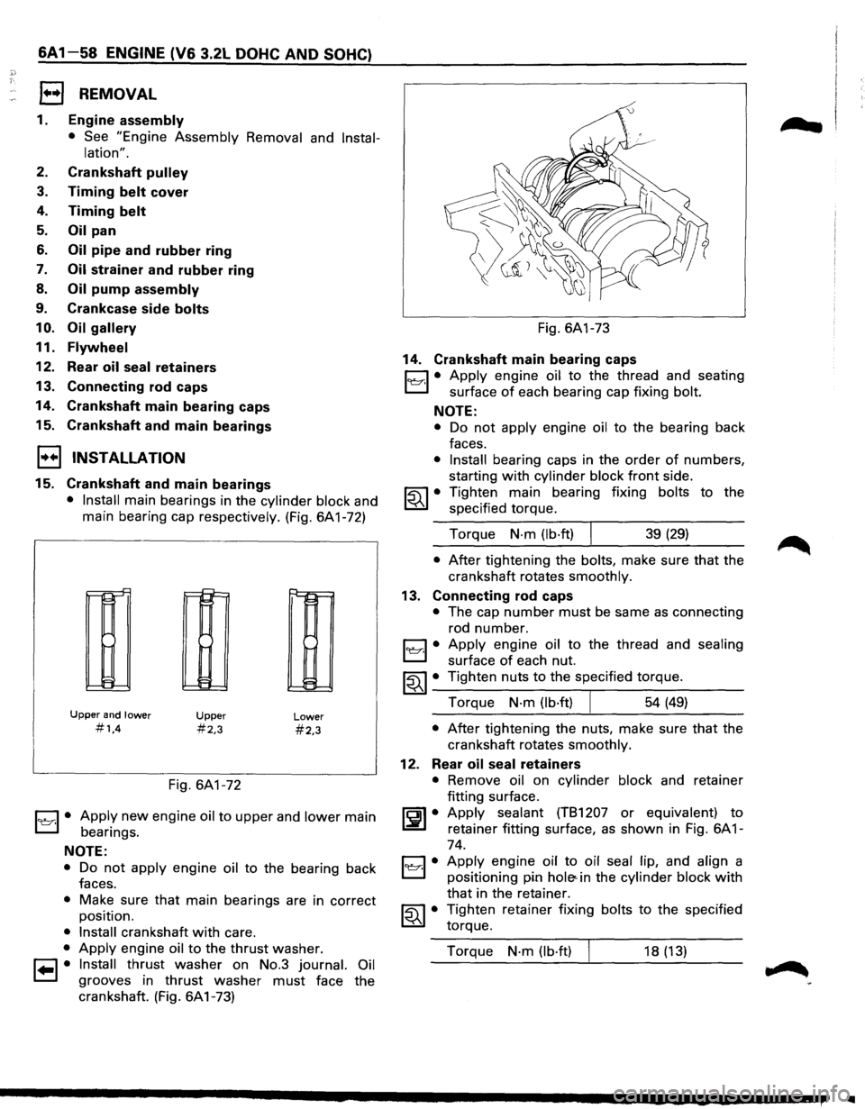
15. Crankshaft and main bearings
• Install main bearings in the cylinder block and
main bearing cap respectively. (Fig. 6A1-72)
r-r-'
II-
!:=
Upper and lower
#1,4
~
!::
E:
Upper
#2,3
Fig. 6A1-72
Lower
#2,3
1~1· Apply new engine oil to upper and lower main
bearings.
NOTE:
• Do not apply engine oil to the bearing back
faces.
• Make sure that main bearings are in correct
position.
• Install crankshaft with care.
• Apply engine oil to the thrust washer.
1•1• Install thrust washer on No.3 journal. Oil
grooves in thrust washer must face the
crankshaft. (Fig. 6A1-73) Fig.
6A1-73
14. Crankshaft main bearing caps
C1 • Apply engine oil to the thread and seating
L:::J surface of each bearing cap fixing bolt.
NOTE:
• Do not apply engine oil to the bearing back
faces.
• Install bearing caps in the order of numbers,
starting
with cylinder block front side.
~~~ • Tighten main bearing fixing bolts to the
specified torque.
Torque
N·m (lb·ft) I 39 (29)
• After tightening the bolts, make sure that the
crankshaft rotates
smoothly.
13. Connecting rod caps
• The cap number must be same as connecting
rod number.
1~1· Apply engine oil to the thread and sealing
surface of each nut.
~~~· Tighten nuts to the specified torque.
Torque
N·m (lb·ft) 54 (49)
• After tightening the nuts, make sure that the
crankshaft rotates
smoothly.
12. Rear oil seal retainers
• Remove oil on cylinder block and retainer
fitting surface.
~~~· Apply sealant (TB1207 or equivalent) to
retainer fitting surface, as shown in Fig. 6A 1-
74.
C1 • Apply engine oil to oil seal lip, and align a
El positioning pin hole< in the cylinder block with
that in the retainer.
~~~· Tighten retainer fixing bolts to the specified
torque.
Torque
N·m (lb·ft) 18 (13)
IIIII
Page 685 of 1928
CHARGING SYSTEM 603 - 9
Fig. 603-19
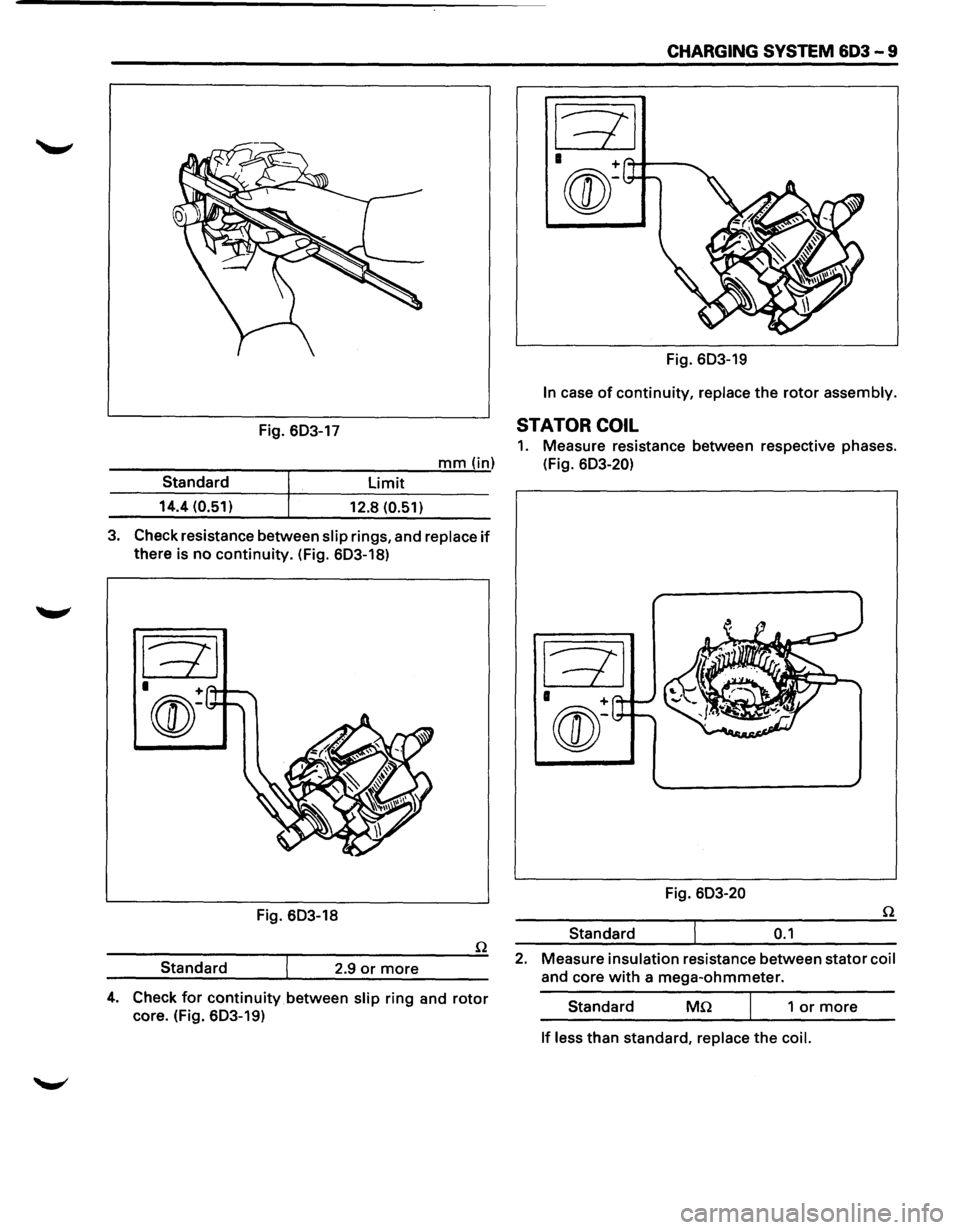
In case of continuity, replace the rotor assembly.
Fig. 603-17 STATOR COIL
1. Measure resistance between respective phases.
---------r-----:-:--:---'m;.;..;.;...;.m""'"(.....,..in) (Fig. 603-20)
limit Standard
14.4 (0.51)
12.8 (0.51)
3. Check resistance between slip rings, and replace if
there is no continuity. (Fig. 603-18)
Fig. 603-18
Standard 2.9
or more
4. Check for continuity between slip ring and rotor
core. (Fig. 603-19) Fig.
603-20
Standard
0.1
2. Measure insulation resistance between stator coil
and core with a mega-ohmmeter.
Standard
Mn 1 or more
If less than standard, replace the coil.
Page 689 of 1928
IGNITION SYSTEM 6D4 - 1
SECTION 604
IGNITION SYSTEM
CONTENTS
General Description ...................... .
Diagnosis
................................... .
On-Vehicle Service ....................... .
Spark Plug Wire ....................... .
Spark Plug .............................. . 6D4-1
6D4-2 6D4-3
6D4-3
6D4-3
Electronic Ignition (EI) Assembly ...
Crankshaft Position Sensor
(CKP sensor) ........................ .
Torque Specifications
................ .
Main Data and Specifications
......... . 6D4-5
6D4-5
6D4-6
6D4-7
GENERAL DESCRIPTION
Ignition is done by the Electronic Ignition (EI) that
fires directly the ignition plugs from ignition coils
through spark plug wires without using a distributor.
A pair of ignition coils for the cylinders having differ
ent phases by 360° (No.1 and No.4, No.2 and No.5,
No.3 and No.6) are
fired simultaneously.
Since the cylinder on exhaust stoke requires less
energy to fire its ignition plug, energy from the
ignition coils can be utilized to fire the mating cylin
der on compression stroke. After additional 360°
rotation, respective cylinder stokes are reversed.
TheEl consists of three ignition coils, ignition control
module, crank angle sensor, Engine Control Module
(ECM) and other components.
Module is provided under the ignition coil, connected
with ECM by means of 6-pin connector. The
ignition control module turns on/off the primary
circuit of ignition coils, and also it controls the igni
tion timing at the engine
speed below 538 rpm.
A notch in
the timing disc on the crankshaft activates
the crank angle sensor which then sends information
such as firing order and starting timing of each
ignition coil to the ECM.
Further, the El employs Ignition Control (I C) to control
similar to a distributor system.
By receiving
signals such as crank position, engine
speed, water temperature and Manifold Absolute
Pressure (MAP), the ECM controls the ignition timing.
Page 691 of 1928
![ISUZU TROOPER 1995 User Guide IGNITION SYSTEM 604 - 3
ON-VEHICLE SERVICE
SPARK PLUG WIRES
EJ REMOVAL
Preparation
• Disconnect battery ground cable.
1. Spark plug wires (Fig. 604-2)
Fig. 6D4-2
(1!] INSPECTION AND REPAIR](/img/61/57183/w960_57183-690.png "ISUZU TROOPER 1995 User Guide IGNITION SYSTEM 604 - 3
ON-VEHICLE SERVICE
SPARK PLUG WIRES
EJ REMOVAL
Preparation
• Disconnect battery ground cable.
1. Spark plug wires (Fig. 604-2)
Fig. 6D4-2
(1!] INSPECTION AND REPAIR")
IGNITION SYSTEM 604 - 3
ON-VEHICLE SERVICE
SPARK PLUG WIRES
EJ REMOVAL
Preparation
• Disconnect battery ground cable.
1. Spark plug wires (Fig. 604-2)
Fig. 6D4-2
(1!] INSPECTION AND REPAIR
Check the high tension cable for insulation. Check
terminals for corrosion or damage, and replace as
necessary.
Measuring resistance of spark plug wires (kQ)
Spare plug wires SOHC DOHC
No.1 cable 6.4-14.9 6.2-14.2
No.2 cable 5.7-13.1 7.2-16.7
No.3 cable 6.2-14.4 6.5-14.9
No.4 cable 5.8-13.3 6.8-15.8
No.5 cable 6.4-14.9 6.9-16.0
No.6 cable 6.9-16.0 6.3-14.5
Measure resistance
of spark plug wires, and replace
the cable if its value exceeds the standard. (Fig. 6D4-
3)
Fig. 6D4-3
B INSTALLATION
1. Spark plug wires
• Connect ignition coils and spark plugs with
spark plug wires respectively. Match each
number (cylinder No.) marked on the ignition
coil with that on spark plug wire, and connect
each spark
plug for the cylinder. (Fig. 6D4-4)
LH bank
y Front
#4-
#1--
1®®®1
RH Bank
Connecting Position of Spark plug wire
Fig. 6D4-4
• Connect battery ground cable.
"f CAUTION
Do not cross, twist or pull the spark plug wires.
SPARK PLUG
EJ REMOVAL
1. Spare plug wires
2. Spark plugs (Fig. 604-5)
Page 693 of 1928
[!!) INSTALLATION
2. Spark plugs
• Tighten spark plugs to the specified torque.
1. Spark plug wires
• Connect high tension cables to correct termi
nals respectively.
~~~ Torque N·m (lb·ft) I
ELECTRONIC IGNITION (EI)
ASSEMBLY
EJ REMOVAL
Preparation
• Disconnect battery ground cable
1. Spark plug wires
2. Wiring connectors
18 (13)
• Disconnect connectors on Engine Control
Module (ECM), power supply and crank angle
sensor.
3. Electronic Ignition (EI) assembly
• Remove three fixing bolts, then the El assem
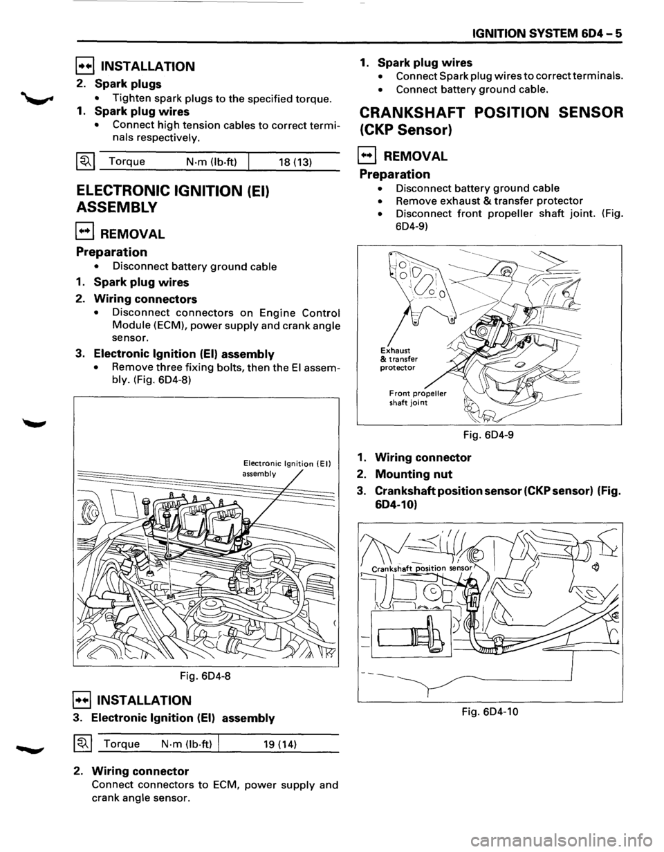
bly. (Fig. 6D4-8)
Fig. 6D4-8
E]INSTALLATION
Electronic Ignition (Ell assembly
3. Electronic Ignition (EI) assembly
~~~ Torque N·m (lb·ftl I 19 (14)
2. Wiring connector
Connect connectors to ECM, power supply and
crank
angle sensor.
IGNITION SYSTEM 604-5
1. Spark plug wires
• Connect Spark plug wires to correct terminals.
• Connect battery ground cable.
CRANKSHAFT POSITION SENSOR
(CKP Sensor)
E) REMOVAL
Preparation
• Disconnect battery ground cable
•
Remove exhaust & transfer protector
• Disconnect front propeller shaft joint. (Fig.
6D4-9)
Fig. 6D4-9
1. Wiring connector
2. Mounting nut
3. Crankshaft position sensor (CKP sensor) (Fig.
604-10)
Fig. 6D4-10
Page 700 of 1928
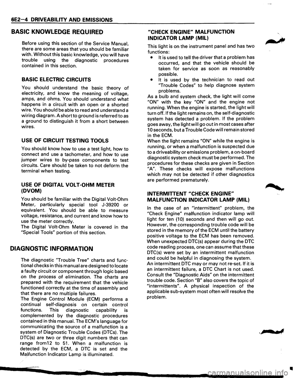
6E2-4 DRIVEABILITY AND EMISSIONS
BASIC KNOWLEDGE REQUIRED
Before using this section of the Service Manual,
there are some areas that you should be familiar
with. Without this basic knowledge, you will have
trouble using the diagnostic procedures
contained in this section.
BASIC ELECTRIC CIRCUITS
You should understand the basic theory of
electricity, and know the meaning of voltage,
amps, and ohms. You should understand what
happens in a circuit with an open or a shorted
wire. You
should be able to read and understand a
wiring diagram. A shortto ground is referred to as
a ground to distinguish it from a short between
wires.
USE OF CIRCUIT TESTING TOOLS
You should know how to use a test light, how to
connect and use a tachometer, and
how to use
jumper wires to by-pass components to test
circuits. Care
should be taken to not deform the
terminal when testing.
USE OF DIGITAL VOLT-OHM METER
(DVOM)
You should be familiar with the Digital Volt-Ohm
Meter, particularly special tool J-39200 or
equivalent. You should be able to measure
voltage, resistance, and current and know how to
use the meter correctly.
The
Digital Volt-Ohm Meter is covered in the
"Special Tools" portion of this section.
DIAGNOSTIC INFORMATION
The diagnostic "Trouble Tree" charts and func
tional checks in this manual are designed to locate
a faulty circuit or component through logic based
on the process
of elimination. The charts are
prepared
with the requirement that the vehicle
functioned correctly at the time of assembly and
that there are no multiple failures.
The Engine Control Module (ECM) performs a
continual self-diagnosis on certain control
functions. This diagnostic capability is
complemented by the diagnostic procedures
contained in this
manual. The ECM's language for
communicating the source of a malfunction is a
system
of Diagnostic Trouble Codes (DTCs). The
DTC(s) are
two or three digit numbers that can
range from12 to
51. When a malfunction is
detected by the ECM, a DTC is set and the
Malfunction Indicator Lamp is illuminated.
"CHECK ENGINE" MALFUNCTION
INDICATOR
LAMP (MIL)
This light is on the instrument panel and has two
functions:
• It is used to tell the driver that a problem has
occurred, and that the
vehicle should be
taken
for service as soon as reasonably
possible.
• It
is used by the technician to read out
'Trouble Codes" to help diagnose system
problems.
As a bulb and system check, the light will come
"ON" with the key "ON" and the engine not
running. When the engine is started, the light will
turn off. If the light remains on, the self-diagnostic
system has detected a
problem. If the problem
goes away, the light will go out in most cases after
10 seconds, but a Trouble Code will remain stored
in the
ECM.
When the light remains "ON" while the engine is
running,
or when a malfunction is suspected due
to a
driveability or emissions problem, a on-board
diagnostic system check
must be performed. The
procedures
for these checks are given in Section
"A". These checks will expose malfunctions
which may
not be detected if other diagnostics
are performed
prematurely.
INTERMITTENT "CHECK ENGINE"
MALFUNCTION INDICATOR
LAMP (MIL)
In the case of an "intermittent" problem, the
"Check Engine"
malfunction indicator lamp will
light
for ten (1 0) seconds and then will go out.
However, the corresponding
trouble code will be
stored in the
memory of the ECM until the battery
positive
voltage to the ECM has been removed.
When unexpected DTC(s) appear during the
DTC
code reading process, one can assume that these
DTC(s) were set by an intermittent malfunction
and could be helpful in diagnosing the system.
An intermittent
DTC may or may not re-set. If it is
an intermittent failure, a DTC Chart is not used.
Consult the "Diagnostic Aids" on the intermittent
trouble code. Section "B" also covers the topic of
"intermittents". A physical inspection of the
applicable sub-system most often will resolve the
problem.
II
Page 716 of 1928
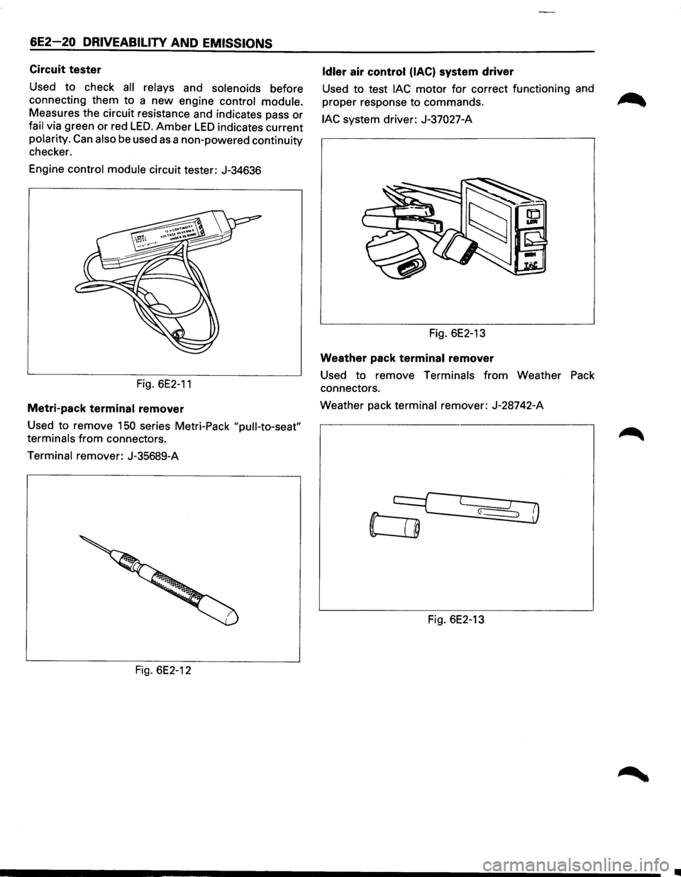
6E2-20 DRIVEABILITV AND EMISSIONS
Circuit tester
Used to check all relays and solenoids before
connecting them to a
new engine control module.
Measures the circuit resistance and indicates pass or
fail via green or red LED. Amber LED indicates current
polarity. Can also be used as a non-powered continuity
checker.
Engine
control module circuit tester: J-34636
Fig.
6E2-11
Metri-pack terminal remover
Used to remove 150 series Metri-Pack "pull-to-seat"
terminals
from connectors.
Terminal remover: J-35689-A
Fig. 6E2-12
Idler air control (lAC) system driver
Used to test lAC motor for correct functioning and
proper response to commands.
lAC system driver: J-37027-A
Fig. 6E2-13
Weather pack terminal remover
Used to remove Terminals from Weather Pack
connectors.
Weather pack terminal remover: J-28742-A
Fig. 6E2-13
•
Page 772 of 1928
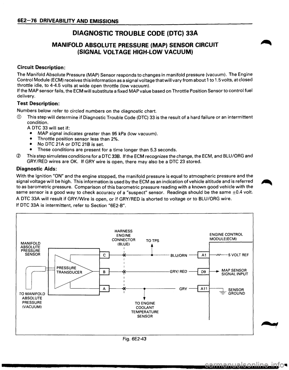
6E2-76 DRIVEABILITY AND EMISSIONS
DIAGNOSTIC TROUBLE CODE (DTC) 33A
MANIFOLD ABSOLUTE PRESSURE (MAP) SENSOR CIRCUIT
(SIGNAL
VOLTAGE HIGH-LOW VACUUM)
Circuit Description:
The Manifold Absolute Pressure {MAP) Sensor responds to changes in manifold pressure (vacuum). The Engine
Control Module (ECM) receives this information as a signal voltage that will vary from about 1 to 1.5 volts, at closed
throttle idle, to 4-4.5 volts at
wide open throttle (low vacuum).
If the MAP sensor fails, the ECM will substitute a fixed MAP value based on Throttle Position Sensor to control fuel
delivery.
Test Description:
Numbers below refer to circled numbers on the diagnostic chart.
CD This step will determine if Diagnostic Trouble Code (DTC) 33 is the result of a hard failure or an intermittent
condition.
A
DTC 33 will set if:
• MAP signal indicates greater than 95 kPa (low vacuum).
• Throttle position sensor less than 2%.
• No DTC 21 A or DTC 21 B is set.
• These conditions are present for a time longer than 5.3 seconds.
® This step simulates conditions for a DTC 338. If the ECM recognizes the change, the ECM, and BLU/ORG and
GRY /RED wires are OK. If GRY wire is open, there may also be a DTC 23 stored.
Diagnostic Aids:
With the Ignition "ON" and the engine stopped, the manifold pressure is equal to atmospheric pressure and the
signal voltage
will be high. This information is used by the ECM as an indication of vehicle altitude and is referred ~
to as barometric pressure. Comparison of this barometric pressure reading with a known good vehicle with the
same sensor is a good
way to check accuracy of a "suspect" sensor. Readings should be the same ±0.4 volt.
A
DTC 33A will result if GRY /Wire is open, or if GRY /RED is shorted to voltage or to BLU/ORG wire.
If DTC 33A is intermittent, refer to Section "6E2-B".
MANIFOLD ABSOLUTE
PRESSURE
SENSOR
TO MANIFOLD ....__ _______ __,
ABSOLUTE
PRESSURE
(VACUUM)
HARNESS ENGINE
CONNECTOR
(BLUE) TOTPS
TO ENGINE
COOLANT
TEMPERATURE SENSOR
Fig. 6E2-43
GRY
ENGINE CONTROL MODULE(ECM)
t---~W--5 VOLT REF
SENSOR
- GROUND
Page 774 of 1928
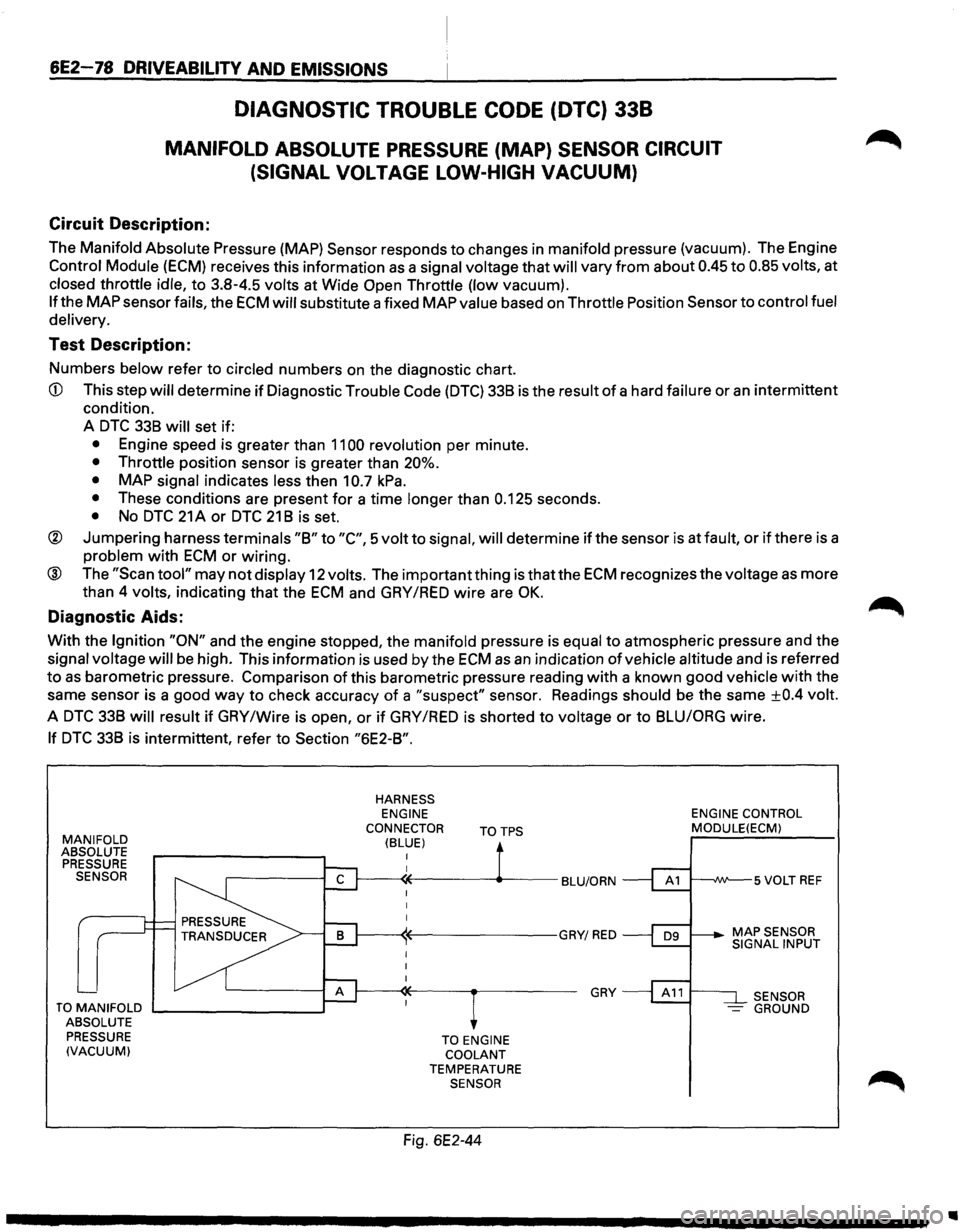
6E2-78 DRIVEABILITV AND EMISSIONS
DIAGNOSTIC TROUBLE CODE (DTC) 338
MANIFOLD ABSOLUTE PRESSURE (MAP) SENSOR CIRCUIT
(SIGNAL
VOLTAGE LOW-HIGH VACUUM)
Circuit Description:
The Manifold Absolute Pressure (MAP) Sensor responds to changes in manifold pressure (vacuum). The Engine
Control Module (ECM) receives this information as a signal voltage that will vary from about 0.45 to 0.85 volts, at
closed throttle idle, to 3.8-4.5 volts at Wide Open Throttle (low vacuum).
If the MAP sensor fails, the ECM will substitute a fixed MAP value based on Throttle Position Sensor to control fuel
delivery.
Test Description:
Numbers below refer to circled numbers on the diagnostic chart.
CD This step will determine if Diagnostic Trouble Code (DTC) 338 is the result of a hard failure or an intermittent
condition.
A
DTC 338 will set if:
• Engine speed is greater than 1100 revolution per minute.
• Throttle position sensor is greater than 20%.
•
MAP signal indicates less then 10.7 kPa.
• These conditions are present for a time longer than 0.125 seconds.
• No DTC 21 A or DTC 21 8 is set.
® Jumpering harness terminals "8" to "C", 5 volt to signal, will determine if the sensor is at fault, or if there is a
problem with ECM or wiring.
® The "Scan tool" may not display 12 volts. The important thing is that the ECM recognizes the voltage as more
than 4
volts, indicating that the ECM and GAY /RED wire are OK.
Diagnostic Aids:
With the Ignition "ON" and the engine stopped, the manifold pressure is equal to atmospheric pressure and the
signal voltage will be high. This information is used by the ECM as an indication of vehicle altitude and is referred
to as barometric pressure. Comparison of this barometric pressure reading with a known good vehicle with the
same sensor is a good
way to check accuracy of a "suspect" sensor. Readings should be the same ±0.4 volt.
A DTC 338 will result if GAY /Wire is open, or if GAY /RED is shorted to voltage or to 8LUIORG wire.
If DTC 338 is intermittent, refer to Section "6E2-8".
MANIFOLD ABSOLUTE
PRESSURE SENSOR
TO MANIFOLD .._ _______ --.~
ABSOLUTE
PRESSURE
(VACUUM)
HARNESS ENGINE
CONNECTOR
(BLUE) TOTPS
TO ENGINE COOLANT TEMPERATURE SENSOR
Fig. 6E2-44
GRY
ENGINE CONTROL MODULE(ECM)
SENSOR -GROUND
..
Page 782 of 1928
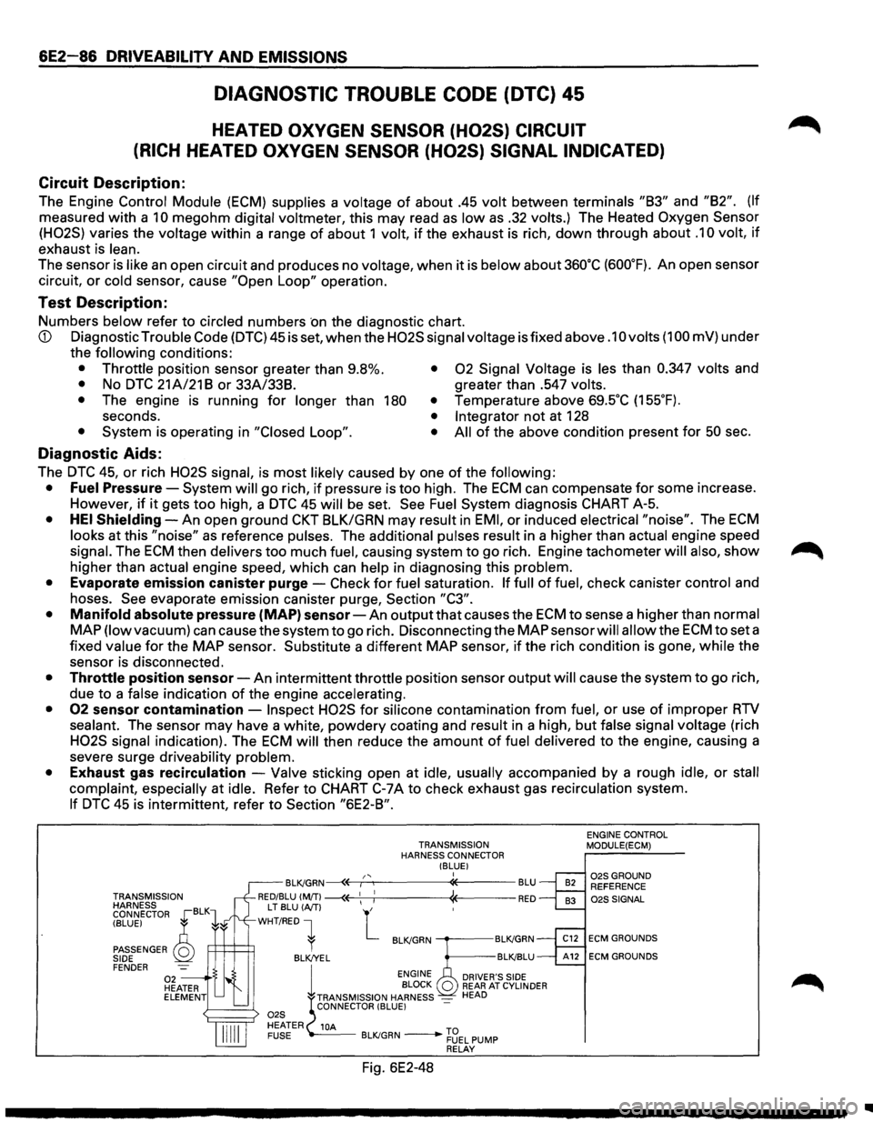
6E2-86 DRIVEABILITY AND EMISSIONS
DIAGNOSTIC TROUBLE CODE (DTC) 45
HEATED OXYGEN SENSOR (H02S) CIRCUIT
(RICH
HEATED OXYGEN SENSOR (H02S) SIGNAL INDICATED)
Circuit Description:
The Engine Control Module (ECM) supplies a voltage of about .45 volt between terminals "83" and "82". (If
measured with a 10 megohm digital voltmeter, this may read as low as .32 volts.) The Heated Oxygen Sensor
(H02S)
varies the voltage within a range of about 1 volt, if the exhaust is rich, down through about .1 0 volt, if
exhaust is lean.
The sensor is like an open circuit and produces no voltage, when it is below about 360"C (600"F). An open sensor
circuit,
or cold sensor, cause "Open Loop" operation.
Test Description:
Numbers below refer to circled numbers ·on the diagnostic chart.
CD Diagnostic Trouble Code (DTC) 45 is set, when the H02S signal voltage is fixed above .1 0 volts (1 00 mV) under
the
following conditions:
• Throttle position sensor greater than 9.8%. • 02 Signal Voltage is les than 0.347 volts and
• No DTC 21 A/21 8 or 33A/338. greater than .547 volts.
•
The engine is running for longer than 180 • Temperature above 69.5"C (155"F).
seconds. • Integrator not at 128
• System is operating in "Closed Loop". • All of the above condition present for 50 sec.
Diagnostic Aids:
The DTC 45, or rich H02S signal, is most likely caused by one of the following:
• Fuel Pressure-System will go rich, if pressure is too high. The ECM can compensate for some increase.
However,
if it gets too high, a DTC 45 will be set. See Fuel System diagnosis CHART A-5.
• HEI Shielding-An open ground CKT BLK/GRN may result in EMI, or induced electrical "noise". The ECM
looks at this "noise" as reference pulses. The additional pulses result in a higher than actual engine speed
signal. The ECM then delivers too much fuel, causing system to go rich. Engine tachometer will also, show ~
higher than actual engine speed, which can help in diagnosing this problem.
• Evaporate emission canister purge-Check for fuel saturation. If full of fuel, check canister control and
hoses.
See evaporate emission canister purge, Section "C3".
• Manifold absolute pressure (MAP) sensor-An output that causes the ECM to sense a higher than normal
MAP (low vacuum) can causethesystemto go rich. Disconnecting the MAP sensor will allow the ECMtoseta
fixed value for the MAP sensor. Substitute a different MAP sensor, if the rich condition is gone, while the
sensor is disconnected.
• Throttle position sensor-An intermittent throttle position sensor output will cause the system to go rich,
due
to a false indication of the engine accelerating.
• 02 sensor contamination -Inspect H02S for silicone contamination from fuel, or use of improper RTV
sealant. The sensor may have a white, powdery coating and result in a high, but false signal voltage (rich
H02S signal indication). The ECM will then reduce the amount of fuel delivered to the engine, causing a
severe surge driveability problem.
• Exhaust gas recirculation -Valve sticking open at idle, usually accompanied by a rough idle, or stall
complaint, especially at idle. Refer to CHART C-7A to check exhaust gas recirculation system.
If DTC 45 is intermittent, refer to Section "6E2-8".
TRANSMISSION
HARNESS
CONNECTOR ,[BLK1
TRANSMISSION
HARNESS CONNECTOR !BLUE I I ,, BLK!GRN~E----r:......,-----"*----BLU
RED/BLU (MfT) ~ 1
1 1 RED
(BLUE) ~
PASSENGER Q SIDE FENDER
L T
BLU (AfT) L WHT/RED 1
R=+=+=:R l BLK!GRN -----BLK!GRN
BLK/YEL BLK!BLU
1
ENGINE
BLOCK Q TRANSMISSION HARNESS -CONNECTOR (BLUE) -
DRIVER'S SIDE REAR AT CYLINDER HEAD
10A BLK/GRN -~~EL PUMP RELAY
Fig. 6E2-48
ENGINE CONTROL MODULE(ECM)
02SGROUND REFERENCE 02S SIGNAL
ECM GROUNDS
ECM GROUNDS
..