ESP ISUZU TROOPER 1995 Repair Manual
[x] Cancel search | Manufacturer: ISUZU, Model Year: 1995, Model line: TROOPER, Model: ISUZU TROOPER 1995Pages: 1928
Page 1702 of 1928
9J-78 Supplemental Restraint System
DTC35 ~
DISCRIMINATING SENSOR OPEN OR MISSING
CIRCUIT DESCRIPTION
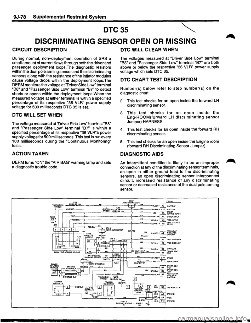
During normal, non-deployment operation of SRS a
small amount of current flows through both the driver and
passenger deployment loops.The diagnostic resistors
within the dual pole arming sensor and the discriminating
sensors along with the resistance of the inflator modules
cause voltage drops within the deployment loops.The
DERM monitors the voltage at "Driver Side
Low" terminal
"B8" and "Passenger Side Low" terminal "B7' to detect
shorts or opens within the deployment loops.When the
measured voltage at either terminal is within a specified
percentage of its respective
"36 VLR" power supply
voltage for
500 milliseconds DTC 35 is set.
DTC WILL SET WHEN
The voltage measured at "Driver Side Low" terminal "B8"
and "Passenger Side Low" terminal "B7" is within a
specified percentage
of its respective "36 VLR"a power
supply voltage for
500 milliseconds. This test is run every
1
00 milliseconds during the "Continuous Monitoring"
tests.
ACTION TAKEN
DERM turns "ON" the "AIR BAG" warning lamp and sets
a diagnostic trouble code.
...
DTC WILL CLEAR WHEN
The voltages measured at "Driver Side Low" terminal
"B8" and "Passenger Side Low" terminal "B7" are both
above or
below the respective "36 VLR" power supply
voltage which sets
DTC 35.
DTC CHART TEST DESCRIPTION
Number(s) below refer to step number(s) on the
diagnostic chart.
2. This test checks for an open inside the forward LH
discriminating sensor.
3. This test checks for an open inside the
Eng-ROOM(forward LH discriminating sensor
Jumper) HARNESS.
4. This test checks for an open inside the forward RH
discriminating sensor.
5. This test checks for an open inside the Engine room
(forward
RH Discriminating Sensor Jumper)
DIAGNOSTIC AIDS
An intermittent condition is likely to be an improper
connection at any of the discriminating sensor terminals,
an open in either ground feed to the discriminating
sensors,
an open discriminating sensor interconnect
ciircuit, increased resistance
of any discriminating
sensor or decreased resistance of the dual pole arming
sensor.
SRS-1 JOINT CONNECTION ,, .
DRIVER 38VLA PASS. 38VLA PASS. SOURCE SENSE
REDUNDAT INDICATOR GROUND
PASS SIDE HIGH
f---""------o~---4--'T--:f----7-------'..,_-BLKJBLU f---.!W...----o~---4--'T--:)--ITO ~~tc~~BLU
N-:1~i7-7?--.J!2!L--wHTI!'ED Al~L __..Jlli__ BAN CONNECTOR 111t
SERIAL DATA
DRIVER SIDE HIGH DRIVER SIDE lOW REDUNDANT INDICATOR IGNffiON 1
..
Page 1714 of 1928
9J-90 Supplemental Restraint System
DTC51
FRONTAL
CRASH DETECTED
CIRCUIT DESCRIPTION
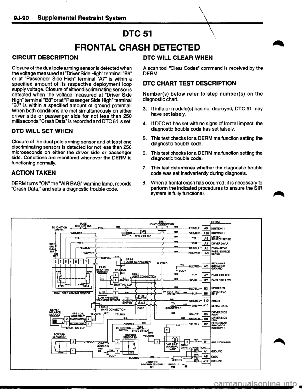
Closure of the dual pole arming sensor is detected when
the voltage measured at "Driver
Side High" terminal "89"
or at "Passenger Side High" terminal "A7" is within a
specified
amount of its respective deployment loop
supply voltage.
Closure of either discriminating sensor is
detected when the voltage measured at "Driver
Side
High" terminal "88" or at "Passenger Side High" terminal
"87" is within a specified amount of ground potential.
When both conditions are met simultaneously
on either
driver side
or passenger side for not less than 250
milliseconds "Crash Data" is recorded and DTC 51 is set.
DTC WILL SET WHEN
Closure of the dual pole arming sensor and at least one
discriminating sensors is detected for not less than
250
microseconds on either the driver side or passenger
side. Conditions are monitored whenever the DERM is
functioning
normally.
ACTION TAKEN
DERM turns "ON" the "AIR BAG" warning lamp, records
"Crash
Data," and sets a diagnostic trouble code.
TO IGNITION SWITCH
FUSE! SRS C-24 10A 1101 R D
DTC WILL CLEAR WHEN
A scan tool "Clear Codes" command is received by the
DERM.
DTC CHART TEST DESCRIPTION
Number(s) below refer to step number(s) on the
diagnostic chart.
3. If inflator module(s) has not deployed, DTC 51 may
have set falsely.
4. If DTC 51 has set with no signs of frontal impact, the
diagnostic trouble code has set falsely.
5. This test checks for a DERM malfunction setting the
diagnostic trouble code.
6. This test checks for a DERM malfunction setting the
diagnostic trouble code.
7. This test determines whether the diagnostic trouble
code was set inadvertently during diagnosis.
8. When a frontal crash has occurred, it is necessary to
perform the indicated procedures to ensure the
SIR
system is fully functional.
IGNITION 1
DRIVER 36VLR PASS.3SVLR PASS. SOURCE SENSE
PASS SIDE HIGH
PASS SIDE LCIW
SERIAL DATA
SAS INDICATOR
Page 1724 of 1928
9J-1 00 Supplemental Restraint System
DTC61
SRS
INDICATOR CIRCUIT FAIL E
CIRCUIT DESCRIPTION
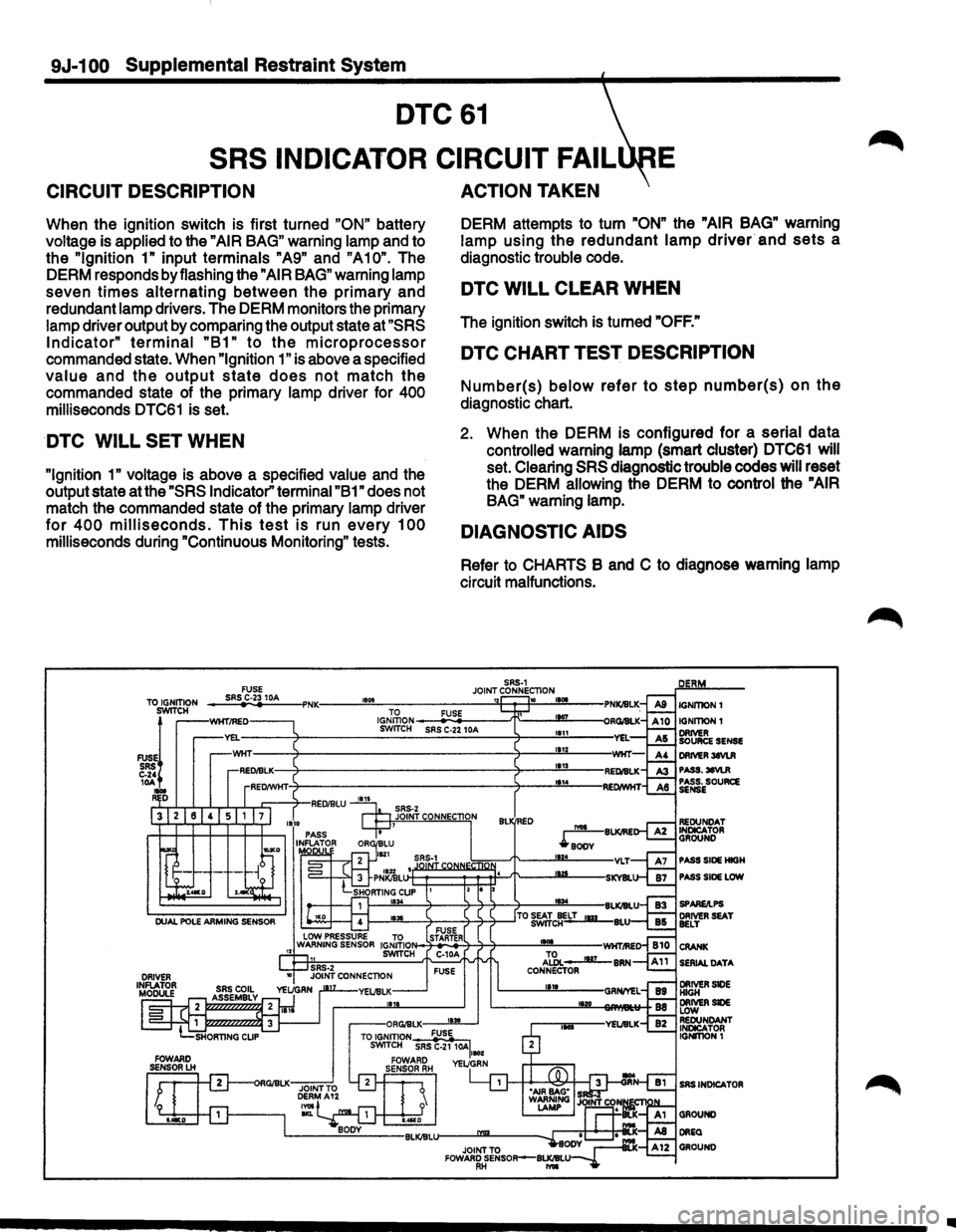
When the ignition switch is first turned "ON" battery
voltage is applied to the
"AIR BAG" warning lamp and to
the
"Ignition 1" input terminals "A9" and "A10". The
DERM responds by flashing the
"AIR BAG" warning lamp
seven
times alternating between the primary and
redundant lamp drivers. The DERM monitors the primary
lamp driver output by comparing the output state at
"SRS
Indicator" terminal "B1" to the microprocessor
commanded state. When "Ignition 1" is above a specified
value and the output state does not match the
commanded state of the primary lamp driver for 400
milliseconds DTC61 is set.
DTC WILL SET WHEN
"Ignition 1" voltage is above a specified value and the
output state at the
"SRS Indicator" terminal "B1" does not
match the commanded state of the primary lamp driver
for 400 milliseconds. This test is run every 100
milliseconds during "Continuous Monitoring" tests.
ACTION TAKEN
DERM attempts to turn "ON" the "AIR BAG" warning
lamp using
the redundant lamp driver and sets a
diagnostic trouble code.
DTC WILL CLEAR WHEN
The ignition switch is turned "OFF."
DTC CHART TEST DESCRIPTION
Number(s) below refer to step number(s) on the
diagnostic chart.
2. When the DERM is configured for a serial data
controlled warning lamp (smart cluster) DTC61 will
set. Clearing
SRS diagnostic trouble codes will reset
the DERM allowing the DERM to control the
"AIR
BAG"
warning lamp.
DIAGNOSTIC AIDS
Refer to CHARTS B and C to diagnose warning lamp
circuit malfunctions.
Ill
Page 1726 of 1928
9J-102 Supplemental Restraint System
DTC62
REDUNDANT SRS INDICATOR CIRCUIT FAIL RE
CIRCUIT DESCRIPTION
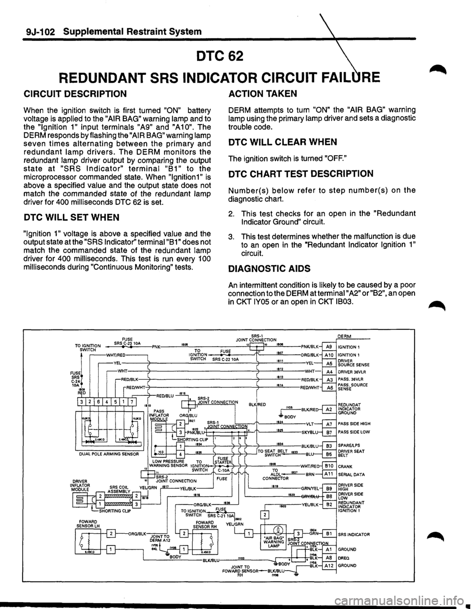
When the ignition switch is first turned "ON" battery
voltage is applied to the
"AIR BAG" warning lamp and to
the
"Ignition 1" input terminals "A9" and "A10". The
DERM responds by flashing the
"AIR BAG" warning lamp
seven
times alternating between the primary and
redundant lamp drivers. The DERM monitors the
redundant lamp driver output by comparing the output
state at "SRS Indicator" terminal "B1" to the
microprocessor commanded state. When
"lgnition1" is
above a specified value and the output state does not
match the commanded state of the redundant lamp
driver for
400 milliseconds DTC 62 is set.
DTC WILL SET WHEN
"Ignition 1" voltage is above a specified value and the
output state at the
"SRS Indicator'' terminal "B 1" does not
match the commanded state of the redundant lamp
driver for
400 milliseconds. This test is run every 100
milliseconds during "Continuous Monitoring" tests.
FUSE
ACTION TAKEN
DERM attempts to turn "ON" the "AIR BAG" warning
lamp using the primary lamp driver and sets a diagnostic
trouble code.
DTC WILL CLEAR WHEN
The ignition switch is turned "OFF."
DTC CHART TEST DESCRIPTION
Number(s) below refer to step number(s) on the
diagnostic chart.
2. This test checks for an open in the "Redundant
Indicator Ground"
circuit.
3. This test determines whether the malfunction is due
to
an open in the "Redundant Indicator Ignition 1"
circuit.
DIAGNOSTIC AIDS
An intermittent condition is likely to be caused by a poor
connection to the DERM at terminal
"A2" or "B2", an open
in
CKT IY05 or an open in CKT IB03.
SRS-1 JOINT CONNECTION ___ sR~SrC~·23~1_M ___ ,PNK:----~"~~------------~"~~~~18~~~--TO IGNITION SWITCH IGNITION 1
FUSE!
SRS C-24 lOA 1800 RED
WKT/RED IGJ~oN ---
PASS SIDE HIGH
PASS SIDE LOW
DRIVER SEAT BELT
CRANK
SERIAL DATA
DRIVER SIDE HIGH DRIVER SIDE LOW REDUNDANT INDICATOR
IGNITION 1
SRS INDICATOR