ESP ISUZU TROOPER 1995 Owner's Manual
[x] Cancel search | Manufacturer: ISUZU, Model Year: 1995, Model line: TROOPER, Model: ISUZU TROOPER 1995Pages: 1928
Page 787 of 1928
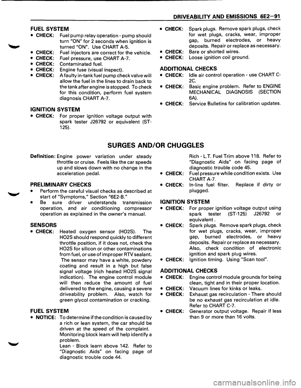
FUEL SYSTEM
• CHECK:
• CHECK:
• CHECK:
• CHECK:
• CHECK:
• CHECK:
Fuel pump relay operation-pump should
turn "ON" for 2 seconds when ignition is
turned
"ON". Use CHART A-5.
Fuel injectors are correct for the vehicle.
Fuel
pressure, use CHART A-7.
Contaminated
fuel.
Engine fuse (visual inspect).
A
faulty in-tank fuel pump check valve will
allow
the fuel in the lines to drain back to
the tank after engine is stopped. To check
for this condition, perform fuel system
diagnosis CHART A-7.
IGNITION SYSTEM
• CHECK: For proper ignition voltage output with
spark tester J26792 or equivalent (ST-
125).
DRIVEABILITY AND EMISSIONS 6E2-91
• CHECK: Spark plugs. Remove spark plugs, check
for wet plugs, cracks, wear, improper
gap, burned electrodes, or heavy
deposits. Repair
or replace as necessary.
• CHECK: Bare or shorted wires.
• CHECK: Loose ignition coil ground.
ADDITIONAL CHECKS
• CHECK: Idle air control operation-use CHART C-
2C.
• CHECK: Basic engine problem. Refer to ENGINE
MECHANICAL DIAGNOSIS (SECTION
6A).
• CHECK: Service Bulletins for calibration updates.
SURGES AND/OR CHUGGLES
Definition: Engine power variation under steady
throttle or cruise. Feels like the car speeds
up and
slows down with no change in the
acceleration pedal.
PRELIMINARY CHECKS
• Perform the careful visual checks as described at
start
of "Symptoms," Section "6E2-B."
•
Be sure driver understands transmission
operation, and air conditioning compressor
operation
as explained in the owner's manual.
SENSORS
• CHECK: Heated oxygen sensor (H02S). The
H02S should respond quickly to different
throttle position, if it does not, check the
H02S for silicon or other contaminations
from fuel, or use of improper RTV sealant.
The sensor may have a white, powdery
coating and result in a high but false
signal voltage
(rich heated H02S signal
indication). The engine control module
will
then reduce the amount of fuel
delivered
to the engine, causing a severe
driveability problem. Also, watch for
green glycol contamination or cracking.
FUEL SYSTEM
• NOTICE: To determine ifthe condition is caused by
a rich
or lean system, the car should be
driven at the speed of the complaint.
Monitoring block learn will help identify a
problem.
Lean -Block learn above 142. Refer to
"Diagnostic Aids" on facing page of
diagnostic trouble code 44.
Rich -L.T. Fuel Trim above 118. Refer to
"Diagnostic Aids" on facing page of
diagnostic trouble code 45.
• CHECK: Fuel pressure while condition exists. Use
CHART A-7.
• CHECK: In-line fuel filter. Replace if dirty or
plugged.
IGNITION SYSTEM
• CHECK: For proper ignition voltage output using
spark tester (ST-125) J26792
or
equivalent .
• CHECK: Spark plugs. Remove spark plugs, check
for wet plugs, cracks, wear, improper
gap, burned electrodes, or heavy
deposits. Repair
or replace as necessary.
Also, check condition of electronic
ignition and spark plug wires.
• CHECK: Ignition timing. Using "Scan tool".
ADDITIONAL CHECKS
• CHECK: Engine control module grounds for being
clean, tight and in their proper location.
• CHECK: Vacuum lines for kinks or leaks.
• CHECK: Exhaust gas recirculation -There should
be no exhaust gas recirculation at idle.
Refer to CHART C-7.
• CHECK: Generator output voltage. Repair if less
than 9 or more than 16 volts.
Page 789 of 1928
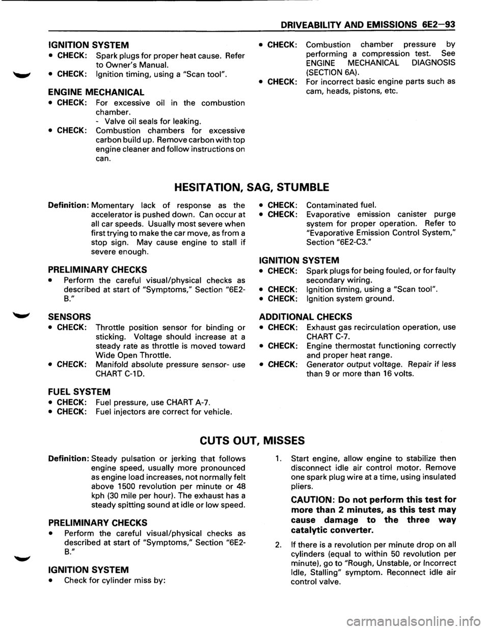
IGNITION SYSTEM
• CHECK: Spark plugs for proper heat cause. Refer
to Owner's Manual.
• CHECK: Ignition timing, using a "Scan tool".
ENGINE MECHANICAL
• CHECK: For excessive oil in the combustion
chamber. -
Valve oil seals for leaking.
• CHECK: Combustion chambers for excessive
carbon
build up. Remove carbon with top
engine cleaner and follow instructions on
can.
DRIVEABILITY AND EMISSIONS 6E2-93
• CHECK: Combustion chamber pressure by
performing a compression test.
See
ENGINE MECHANICAL DIAGNOSIS
(SECTION 6A).
• CHECK: For incorrect basic engine parts such as
cam, heads, pistons, etc.
HESITATION, SAG, STUMBLE
Definition: Momentary lack of response as the
accelerator is pushed down. Can occur at
all car speeds. Usually most severe when
first trying
to make the car move, as from a
stop sign. May cause engine to
stall if
severe enough.
PRELIMINARY CHECKS
• Perform the careful visual/physical checks as
described at start of "Symptoms," Section "6E2-
B."
SENSORS
• CHECK: Throttle position sensor for binding or
sticking. Voltage should increase at a
steady
rate as throttle is moved toward
Wide Open Throttle.
• CHECK: Manifold absolute pressure sensor-use
CHART C-10.
FUEL SYSTEM
• CHECK: Fuel pressure, use CHART A-7.
• CHECK: Fuel injectors are correct for vehicle.
• CHECK: Contaminated fuel.
• CHECK: Evaporative emission canister purge
system
for proper operation. Refer to
"Evaporative Emission Control System,"
Section "6E2-C3."
IGNITION SYSTEM
• CHECK: Spark plugs for being fouled, or for faulty
secondary wiring.
• CHECK: Ignition timing, using a "Scan tool".
• CHECK: Ignition system ground.
ADDITIONAL CHECKS
• CHECK: Exhaust gas recirculation operation, use
CHART
C-7.
• CHECK: Engine thermostat functioning correctly
and proper heat range.
• CHECK: Generator output voltage. Repair if less
than 9 or more than 16 volts.
CUTS OUT, MISSES
Definition: Steady pulsation or jerking that follows
engine speed, usually more pronounced
as engine load increases, not normally felt
above 1500 revolution per minute or 48
kph
(30 mile per hour). The exhaust has a
steady spitting sound at
idle or low speed.
PRELIMINARY CHECKS
• Perform the careful visual/physical checks as
described at start of "Symptoms," Section "6E2-
B."
IGNITION SYSTEM
• Check for cylinder miss by:
1. Start engine, allow engine to stabilize then
disconnect
idle air control motor. Remove
one spark
plug wire at a time, using insulated
pliers.
CAUTION: Do not perform this test for
more than 2 minutes,
as this test may
cause damage to the three
way
catalytic converter.
2. If there is a revolution per minute drop on all
cylinders (equal
to within 50 revolution per
minute), go
to "Rough, Unstable, or Incorrect
Idle, Stalling"
symptom. Reconnect idle air
control valve.
Page 790 of 1928
6E2-94 DRIVEABILITY AND EMISSIONS
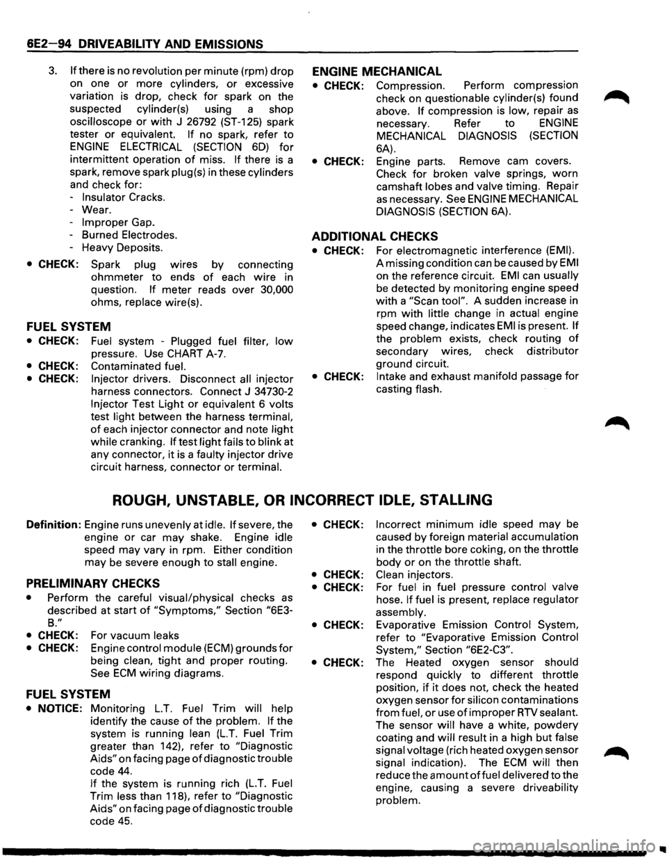
3. If there is no revolution per minute (rpm) drop
on one or more cylinders, or excessive
variation is drop, check
for spark on the
suspected
cylinder(s) using a shop
oscilloscope or with J 26792 (ST-125) spark
tester
or equivalent. If no spark, refer to
ENGINE ELECTRICAL (SECTION 6D) for
intermittent operation of miss. If there is a
spark, remove spark
plug(s) in these cylinders
and check for:
-
Insulator Cracks.
- Wear.
-
Improper Gap.
- Burned
Electrodes.
-Heavy Deposits.
• CHECK: Spark plug wires by connecting
ohmmeter to ends of each wire in
question.
If meter reads over 30,000
ohms, replace wire(s).
FUEL SYSTEM
• CHECK: Fuel system -Plugged fuel filter, low
pressure. Use CHART A-7.
• CHECK: Contaminated fuel.
• CHECK: Injector drivers. Disconnect all injector
harness connectors. Connect
J 34730-2
Injector Test Light or equivalent 6 volts
test light between the harness terminal,
of each injector connector and note light
while
cranking. If test light fails to blink at
any connector, it is a faulty injector drive
circuit harness, connector
or terminal.
ENGINE MECHANICAL
• CHECK: Compression. Perform compression
check on
questionable cylinder(s) found
above.
If compression is low, repair as
necessary. Refer to ENGINE
MECHANICAL DIAGNOSIS (SECTION
6A).
• CHECK: Engine parts. Remove cam covers.
Check
for broken valve springs, worn
camshaft lobes and valve timing. Repair
as necessary. See ENGINE MECHANICAL
DIAGNOSIS (SECTION
6A).
ADDITIONAL CHECKS
• CHECK: For electromagnetic interference (EMI).
A missing condition can be caused by EMI
on the reference circuit. EMI can usually
be detected by monitoring engine speed
with a "Scan tool". A sudden increase in
rpm
with little change in actual engine
speed change, indicates
EMI is present. If
the problem exists, check routing of
secondary wires, check distributor
ground circuit.
• CHECK: Intake and exhaust manifold passage for
casting
flash.
ROUGH, UNSTABLE, OR INCORRECT IDLE, STALLING
Definition: Engine runs unevenly at idle. If severe, the
engine
or car may shake. Engine idle
speed may vary in rpm. Either condition
may be severe enough to stall engine.
PRELIMINARY CHECKS
• Perform the careful visual/physical checks as
described at start
of "Symptoms," Section "6E3-
B."
• CHECK:
• CHECK:
For vacuum leaks
Engine control module (ECM) grounds for
being clean, tight and proper routing.
See ECM wiring diagrams.
FUEL SYSTEM
• NOTICE: Monitoring L.T. Fuel Trim will help
identify the cause of the problem. If the
system is running
lean (LT. Fuel Trim
greater than 142), refer
to "Diagnostic
Aids"
on facing page of diagnostic trouble
code 44.
If the system is running rich (L.T. Fuel
Trim less than 118), refer to "Diagnostic
Aids" on facing page of diagnostic trouble
code 45.
• CHECK:
• CHECK:
• CHECK:
• CHECK:
• CHECK:
Incorrect minimum idle speed may be
caused
by foreign material accumulation
in the throttle bore coking, on the throttle
body or on the throttle shaft.
Clean injectors.
For
fuel in fuel pressure control valve
hose. If fuel is present, replace regulator
assembly.
Evaporative Emission Control System,
refer to "Evaporative Emission Control
System," Section "6E2-C3".
The Heated oxygen sensor should
respond quickly to different throttle
position, if it does not, check the heated
oxygen sensor
for silicon contaminations
from fuel, or use of improper RTV sealant.
The sensor will have a white, powdery
coating and will result in a high but false
signal voltage
(rich heated oxygen sensor
signal indication). The ECM will then
reduce the
amount of fuel delivered to the
engine, causing a severe
driveability
problem.
II
Page 813 of 1928
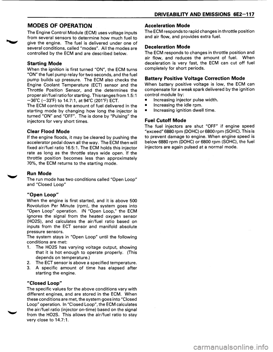
MODES OF OPERATION
The Engine Control Module (ECM) uses voltage inputs
from several sensors to determine how much fuel to
give the engine. The fuel is delivered under one of
several conditions, called "modes". All the modes are
controlled by the ECM and are described below.
Starting Mode
When the ignition is first turned "ON", the ECM turns
"ON" the fuel pump relay for two seconds, and the fuel
pump builds up pressure. The ECM also checks the
Engine
Coolant Temperature (ECT) sensor and the
Throttle Position Sensor, and the determines the
proper
air/fuel ratio for starting. This ranges from 1.5:1
-36·c (-33.F) to 14.7:1, at 94•c (201.F) ECT.
The ECM controls the amount of fuel delivered in the
starting mode by changing
how long the injector is
turned
"ON" and "OFF". The is done by "Pulsing" the
injectors
for very short times.
Clear Flood Mode
If the engine floods, it may be cleared by pushing the
accelerator pedal down all the way. The ECM then will
fixed air/fuel ratio 16.5:1. The ECM holds this injector
rate
as long as the throttle stays wide open. If the
throttle position becomes less than approximately
70%, the ECM returns to the starting mode.
Run Mode
The run mode has two conditions called "Open Loop"
and "Closed Loop"
"Open Loop"
When the engine is first started, and it is above 500
Rovolution Per Minute (rpm), the system goes into
"Open Loop" operation. IN "Open Loop," the ECM
ignores the signal from the heated oxygen sensor
(H02S), and calculates the air/fuel ratio based on
inputs
from the ECT sensor and manifold absolute
pressure sensors.
The system stays in
"Open Loop" until the following
conditions are met:
1. The H02S has varying voltage output, showing
that
it is hot enough to operate properly. (This
depends on temperature.)
2. The ECT sensor is above a specified temperature.
3. A specific amount of time has elapsed after
starting the engine.
"Closed Loop"
The specific values for the above conditions vary with
different engines, and are stored in the ECM. When
these conditions are met, the system goes into
"Closed
Loop"
operation. In "Closed Loop", the ECM calculates
the air/fuel ratio (injector on-time) based on the signal
from the H02S. This allows the air/fuel ratio to stay
very close to 14.7:1.
DRIVEABILITV AND EMISSIONS 6E2-117
Acceleration Mode
The ECM responds to rapid changes in throttle position
and air
flow, and provides extra fuel.
Deceleration Mode
The ECM responds to changes in throttle position and
air
flow, and reduces the amount of fuel. When
deceleration is very fast, the ECM can cut off fuel
completely
for short periods.
Battery Positive Voltage Correction Mode
When battery positive voltage is low, the ECM can
compensate
for a weak spark delivered by the ignition
control module by:
• Increasing injector pulse width.
• Increasing the idle rpm.
• Increasing ignition dwell time.
Fuel Cutoff Mode
The fuel injectors are shut "OFF" if engine speed
"exceed" 6880 rpm (DOHC) or6800 rpm (SOHC). This is
to prevent damage to engine. When engine speed is
below 6880 rpm (DOHC) or 6800 rpm (SOHC), the fuel
injectors are again pulsed at a normal mode.
Page 817 of 1928
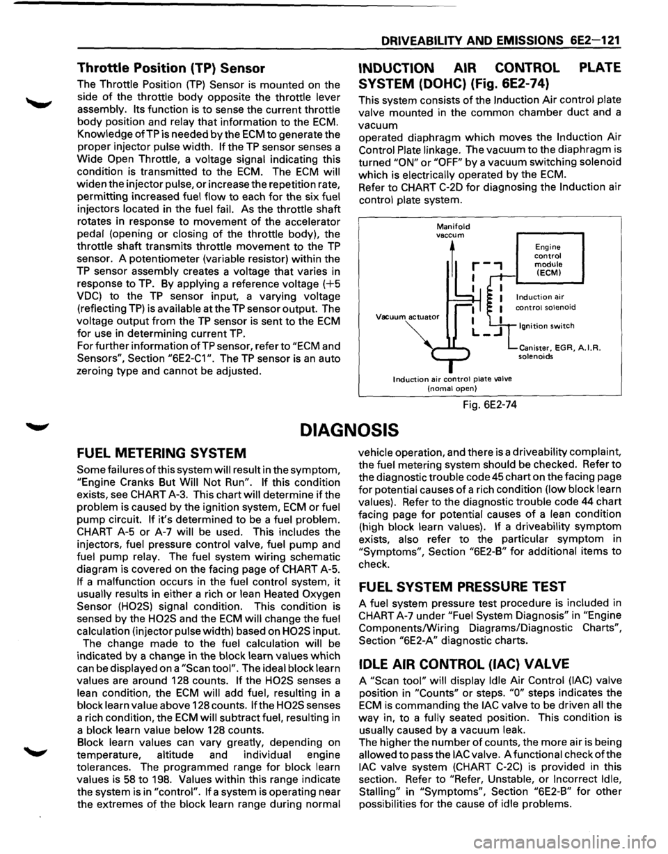
Throttle Position (TP) Sensor
The Throttle Position (TP) Sensor is mounted on the
side
of the throttle body opposite the throttle lever
assembly.
Its function is to sense the current throttle
body position and relay that information to the ECM.
Knowledge ofTP is needed by the ECM to generate the
proper injector pulse width.
If the TP sensor senses a
Wide
Open Throttle, a voltage signal indicating this
condition is transmitted to the
ECM. The ECM will
widen the injector pulse, or increase the repetition rate,
permitting increased fuel
flow to each for the six fuel
injectors located in the fuel fail. As the throttle shaft
rotates in response to
movement of the accelerator
pedal (opening
or closing of the throttle body), the
throttle shaft transmits throttle
movement to the TP
sensor. A potentiometer (variable resistor) within the
TP sensor assembly creates a voltage that varies in
response to
TP. By applying a reference voltage (+5
VDC) to the TP sensor input, a varying voltage
(reflecting
TP) is available at the TP sensor output. The
voltage
output from the TP sensor is sent to the ECM
for use in determining current TP.
For further information ofTP sensor, refer to "ECM and
Sensors", Section
"6E2-C1 ". The TP sensor is an auto
zeroing type and cannot
be adjusted.
DRIVEABILITY AND EMISSIONS 6E2-121
INDUCTION AIR CONTROL PLATE
SYSTEM (DOHC) (Fig. 6E2-74)
This system consists of the Induction Air control plate
valve mounted in the common chamber
duct and a
vacuum operated diaphragm
which moves the Induction Air
Control Plate linkage. The vacuum to the diaphragm is
turned
"ON" or "OFF" by a vacuum switching solenoid
which is electrically operated by the
ECM.
Refer to CHART C-20 for diagnosing the Induction air
control plate system.
Manifold vaccum
1
Vacuum actuator
Induction air control plate valve
(noma! open)
Fig. 6E2-74
Engine control module (ECM)
Ignition switch
Canister, EGR, A.I.R. solenoids
DIAGNOSIS
FUEL METERING SYSTEM
Some failures of this system will result in the symptom,
"Engine Cranks But Will Not Run". If this condition
exists, see CHART A-3. This chart will determine
if the
problem is caused by the ignition system,
ECM or fuel
pump circuit.
If it's determined to be a fuel problem.
CHART A-5
or A-7 will be used. This includes the
injectors, fuel pressure control valve, fuel
pump and
fuel pump relay. The fuel system
wiring schematic
diagram is covered on the facing page
of CHART A-5.
If a malfunction occurs in the fuel control system, it
usually results in either a rich or lean Heated Oxygen
Sensor (H02S) signal condition. This condition is
sensed by the
H02S and the ECM will change the fuel
calculation (injector pulse width) based on
H02S input.
The change made to the fuel calculation will be
indicated
by a change in the block learn values which
can be displayed on a
"Scan tool". The ideal block learn
values are around 128 counts.
If the H02S senses a
lean condition, the
ECM will add fuel, resulting in a
block learn value above 128 counts.
If the H02S senses
a rich condition, the
ECM will subtract fuel, resulting in
a block learn value below 128 counts.
Block learn values can vary greatly, depending on
temperature, altitude and individual engine
tolerances. The programmed range for block learn
values is
58 to 198. Values within this range indicate
the system is in
"control". If a system is operating near
the extremes
of the block learn range during normal vehicle
operation, and there is a driveability complaint,
the fuel metering system should be checked. Refer to
the diagnostic trouble code
45 chart on the facing page
for potential causes of a rich condition (low block learn
values). Refer to the diagnostic trouble code 44 chart
facing page
for potential causes of a lean condition
(high block learn values).
If a driveability symptom
exists, also refer to the particular symptom in
"Symptoms", Section "6E2-B" for additional items to
check.
FUEL SYSTEM PRESSURE TEST
A fuel system pressure test procedure is included in
CHART A-7 under
"Fuel System Diagnosis" in "Engine
Components/Wiring Diagrams/Diagnostic
Charts",
Section "6E2-A" diagnostic charts.
IDLE AIR CONTROL (lAC) VALVE
A "Scan tool" will display Idle Air Control (lAC) valve
position in
"Counts" or steps. "0" steps indicates the
ECM is commanding the lAC valve to be driven all the
way in, to a fully seated position. This condition is
usually caused by a vacuum leak.
The higher the number
of counts, the more air is being
allowed to pass the
lAC valve. A functional check of the
lAC valve system (CHART C-2C) is provided in this
section. Refer to
"Refer, Unstable, or Incorrect Idle,
Stalling"
in "Symptoms", Section "6E2-B" for other
possibilities
for the cause of idle problems.
Page 826 of 1928
6E2-130 DRIVEABILITY AND EMISSIONS
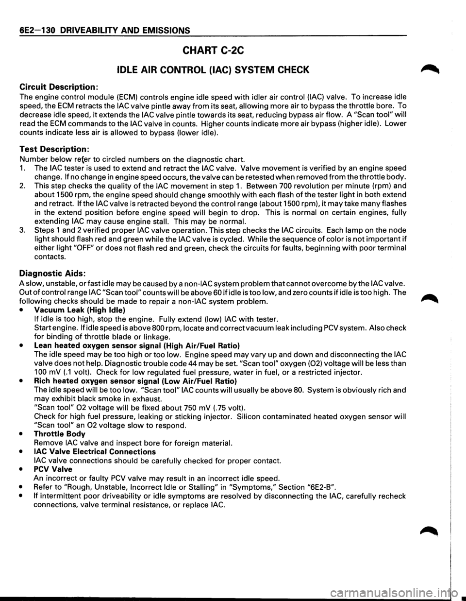
CHART C-2C
IDLE AIR CONTROL (lAC) SYSTEM CHECK
Circuit Description:
The engine control module (ECM) controls engine idle speed with idler air control (lAC) valve. To increase idle
speed, the ECM retracts the lAC valve pintle away from its seat, allowing more air to bypass the throttle bore. To
decrease
idle speed, it extends the lAC valve pintle towards its seat, reducing bypass air flow. A "Scan tool" will
read the ECM commands to the lAC valve in counts. Higher counts indicate more air bypass (higher idle). Lower
counts indicate
less air is allowed to bypass (lower idle).
Test Description:
Number below re{er to circled numbers on the diagnostic chart.
1. The lAC tester is used to extend and retract the lAC valve. Valve movement is verified by an engine speed
change.
If no change in engine speed occurs, the valve can be retested when removed from the throttle body.
2. This step checks the quality of the lAC movement in step 1. Between 700 revolution per minute (rpm) and
about
1500 rpm, the engine speed should change smoothly with each flash of the tester light in both extend
and retract.
If the lAC valve is retracted beyond the control range (about 1500 rpm), it may take many flashes
in the extend position before engine speed will begin to drop. This is normal on certain engines, fully
extending lAC may cause engine stall. This may be normal.
3. Steps 1 and 2 verified proper lAC valve operation. This step checks the lAC circuits. Each lamp on the node
light should flash red and green while the lAC valve is cycled. While the sequence of color is not important if
either light "OFF" or does not flash red and green, check the circuits for faults, beginning with poor terminal
contacts.
Diagnostic Aids:
A slow, unstable, or fast idle may be caused by a non-lAC system problem that cannot overcome by the lAC valve.
Out
of control range lAC "Scan tool" counts will be above 60 if idle is too low, and zero counts if idle is too high. The ..-...
following checks should be made to repair a non-lAC system problem. _......._
• Vacuum Leak (High Idle)
If idle
is too high, stop the engine. Fully extend (low) lAC with tester.
Start engine.
If idle speed is above 800 rpm, locate and correct vacuum leak including PCV system. Also check
for binding of throttle blade or linkage.
•
Lean heated oxygen sensor signal (High Air/Fuel Ratio)
The
idle speed may be too high or too low. Engine speed may vary up and down and disconnecting the lAC
valve
does not help. Diagnostic trouble code 44 may be set. "Scan tool" oxygen (02) voltage will be less than
100 mV (.1 volt). Check for low regulated fuel pressure, water in fuel, or a restricted injector.
• Rich heated oxygen sensor signal (Low Air/Fuel Ratio)
The
idle speed will be too low. "Scan tool" lAC counts will usually be above 80. System is obviously rich and
may exhibit
black smoke in exhaust.
"Scan tool" 02 voltage will be fixed about 750 mV (.75 volt).
Check
for high fuel pressure, leaking or sticking injector. Silicon contaminated heated oxygen sensor will
"Scan
tool" an 02 voltage slow to respond.
• Throttle Body
Remove
lAC valve and inspect bore for foreign material.
• lAC Valve
Electrical Connections
lAC valve
connections should be carefully checked for proper contact.
• PCV Valve
An incorrect or faulty PCV valve may result in an incorrect idle speed.
• Refer to "Rough, Unstable, Incorrect Idle or Stalling" in "Symptoms," Section "6E2-B".
• If
intermittent poor driveability or idle symptoms are resolved by disconnecting the lAC, carefully recheck
connections,
valve terminal resistance, or replace lAC.
Page 922 of 1928
7 A-50 AUTOMATIC TRANSMISSION (4L30-E)
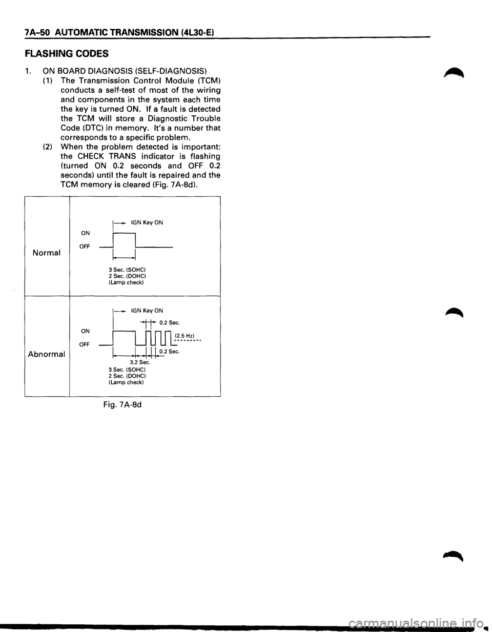
FLASHING CODES
1. ON BOARD DIAGNOSIS (SELF-DIAGNOSIS)
(1) The Transmission Control Module (TCM)
conducts a
self-test of most of the wiring
and components in the system each time
the key is turned ON. If a fault is detected
the TCM
will store a Diagnostic Trouble
Code (DTC) in memory. It's a number that
corresponds to a specific problem.
(2) When the problem detected is important:
the
CHECK TRANS indicator is flashing
(turned ON 0.2 seconds and OFF 0.2
seconds) until the fault is repaired and the
TCM
memory is cleared (Fig. 7A-8d).
ON
~--IGN Key ON
_ll___ OFF Normal w
3 Sec. (SOHC) 2 Sec. (DOHC) (Lamp check)
~-IGNKeyON
ON
"it 0.2Sec.
~~--5-~~)--· OFF
Abnormal \. Ill 0.2 Sec. • 1 ••.. 3.2 Sec. 3 Sec. (SOHC) 2 Sec. (DOHC) (Lamp check)
Fig. 7A-8d
Page 929 of 1928
AUTOMATIC TRANSMISSION (4l30·E) 7 A-57
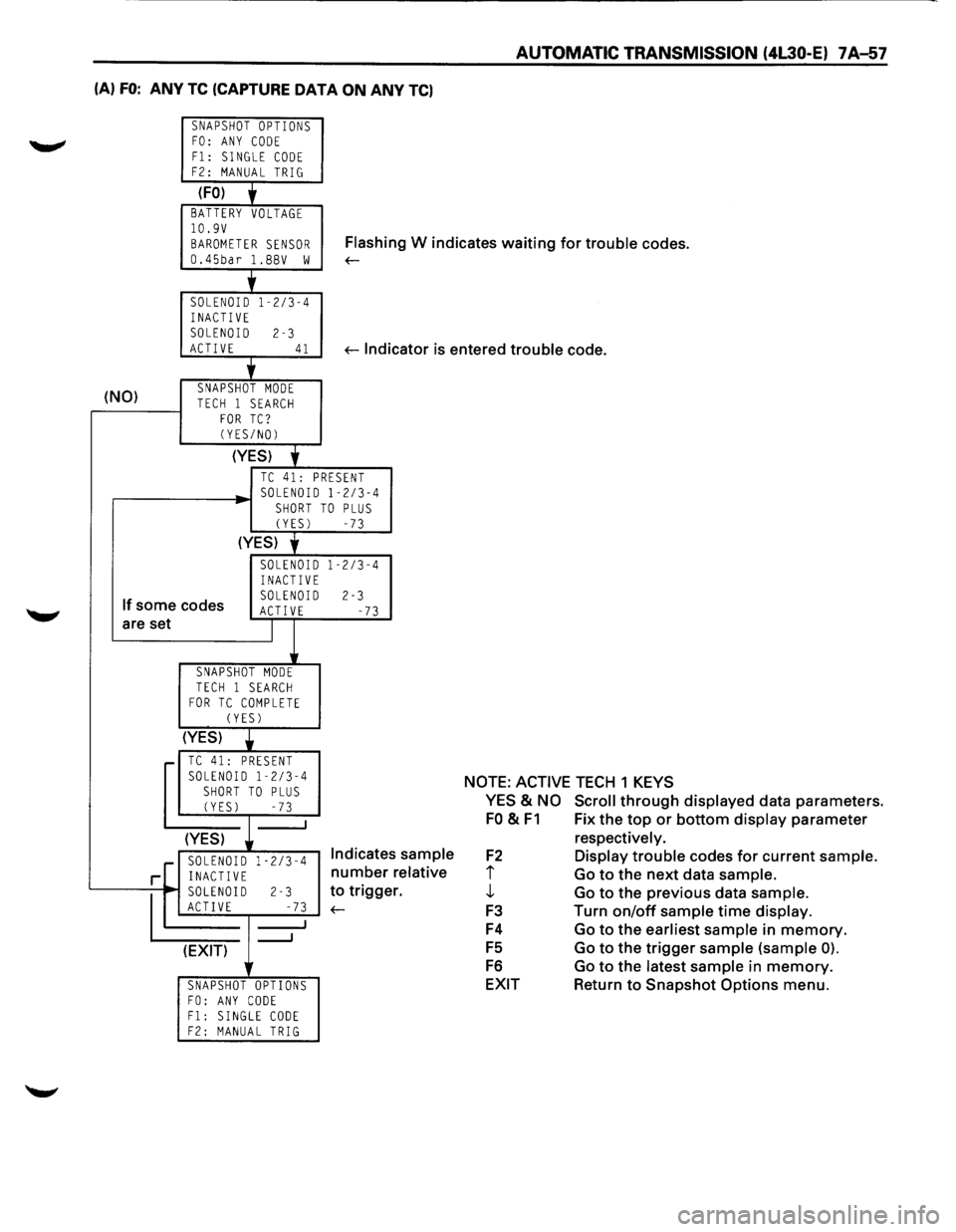
(A) FO: ANY TC (CAPTURE DATA ON ANY TC)
SNAPSHOT OPTIONS FO: ANY CODE
F1: SINGLE CODE F2: MANUAL TRIG
(FO) + BATTERY VOLTAGE 10.9V
BAROMETER SENSOR Flash in g W indicates waiting for trouble codes.
0.45bar l.BBV w ~
'
SOLENOID 1-2/3-4
INACTIVE SOLENOID 2-3 ACTIVE 41 ~lndi cator is entered trouble code.
+
(NO) SNAPSHOT MODE TECH 1 SEARCH FOR TC? (YES/NO)
(YES)
'
TC 41: PRESENT SOLENOID 1-2/3-4 SHORT TO PLUS (YES) -73
(YES) y
SOLENOID 1-2/3-4 INACTIVE
If some codes SOLENOID 2-3 ACT! VE -73 are set I
SNAPSHOT MODE
TECH 1 SEARCH FOR TC COMPLETE (YES)
(YES)
• TC 41: PRESENT SOLENOID 1-2/3-4
SHORT TO PLUS (YES) -73
(YES)
.[ SOLENOID 1-2/3-4 Indicates sample
relative
r. r INACTIVE number
~0
2-3 to trigge
E -73 ~
_J (EXIT) lr
SNAPSHOT OPTIONS FO: ANY CODE F1: SINGLE CODE F2: MANUAL TRIG
NOTE: ACTIVE TECH 1 KEYS
YES
& NO Scroll through displayed data parameters.
FO & F1 Fix the top or bottom display parameter
F2
i j,
F3
F4
FS
F6
EXIT respectively.
Display trouble
codes for current sample.
Go to the next data sample.
Go to the previous data sample.
Turn on/off sample time display.
Go to the earliest sample in memory.
Go to the trigger sample (sample 0).
Go to the latest sample in memory.
Return to Snapshot Options menu.
Page 930 of 1928
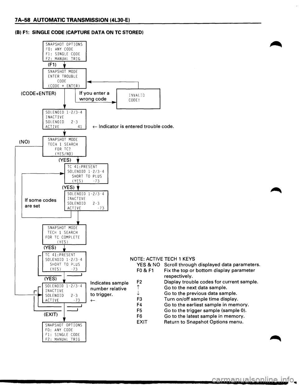
1 A-58 AUTOMATIC TRANSMISSION (4l30-E)
(B) F1: SINGLE CODE (CAPTURE DATA ON TC STORED)
SNAPSHOT OPTIONS FO: ANY CODE
F1: SINGLE CODE F2: MANUAL TRIG
(F1) y
SNAPSHOT MODE ENTER TROUBLE
CODE (CODE + ENTER) -
(CODE+ENTER) If you
enter a
wrong code
..
SOLENOID 1-2/3-4 INACTIVE
SOLENOID 2-3
I
INVALID CODE!
ACTIVE 41 ~ Indicator is entered trouble code.
(NO) '
SNAPSHOT MODE
TECH 1 SEARCH FOR TC? CYES/NOl
(YES) f
TC 41:PRESENT
,...-------~ SOLENOID 1-2/3-4 SHORT TO PLUS (YES) -73
(YES) f
If some codes
SOLENOID 1-2/3-4 INACTIVE
are set SOLENOID 2-3 ACTIVE -73
I
SNAPSHOT MODE TECH 1 SEARCH FOR TC COMPLETE (YES)
(YES) •
.-TC41:PRESENT SOLENOID 1-2/3-4 SHORT TO PLUS (YES) -73 _j
(YES)
1-2/3-4 r SOLENOID
rL INACTIVE
'------,~, SOLEN~ 1-,D ;------l-2 _: ;...;;.3---'
(EXIT)
SNAPSHOT OPTIONS
FO: ANY CODE F1: SINGLE CODE F2: MANUAL TRIG
Indicates sample
number relative
to trigger.
~
NOTE: ACTIVE TECH 1 KEYS
YES & NO Scroll through displayed data parameters.
FO & F1 Fix the top or bottom display parameter
F2
i j_
F3
F4
F5
F6
EXIT respectively.
Display trouble
codes for current sample.
Go to the next data sample.
Go to the previous data sample.
Turn on/off sample time display.
Go to the earliest sample in memory.
Go to the trigger
sample (sample 0).
Go to the latest sample in memory.
Return to Snapshot Options menu.
Page 931 of 1928
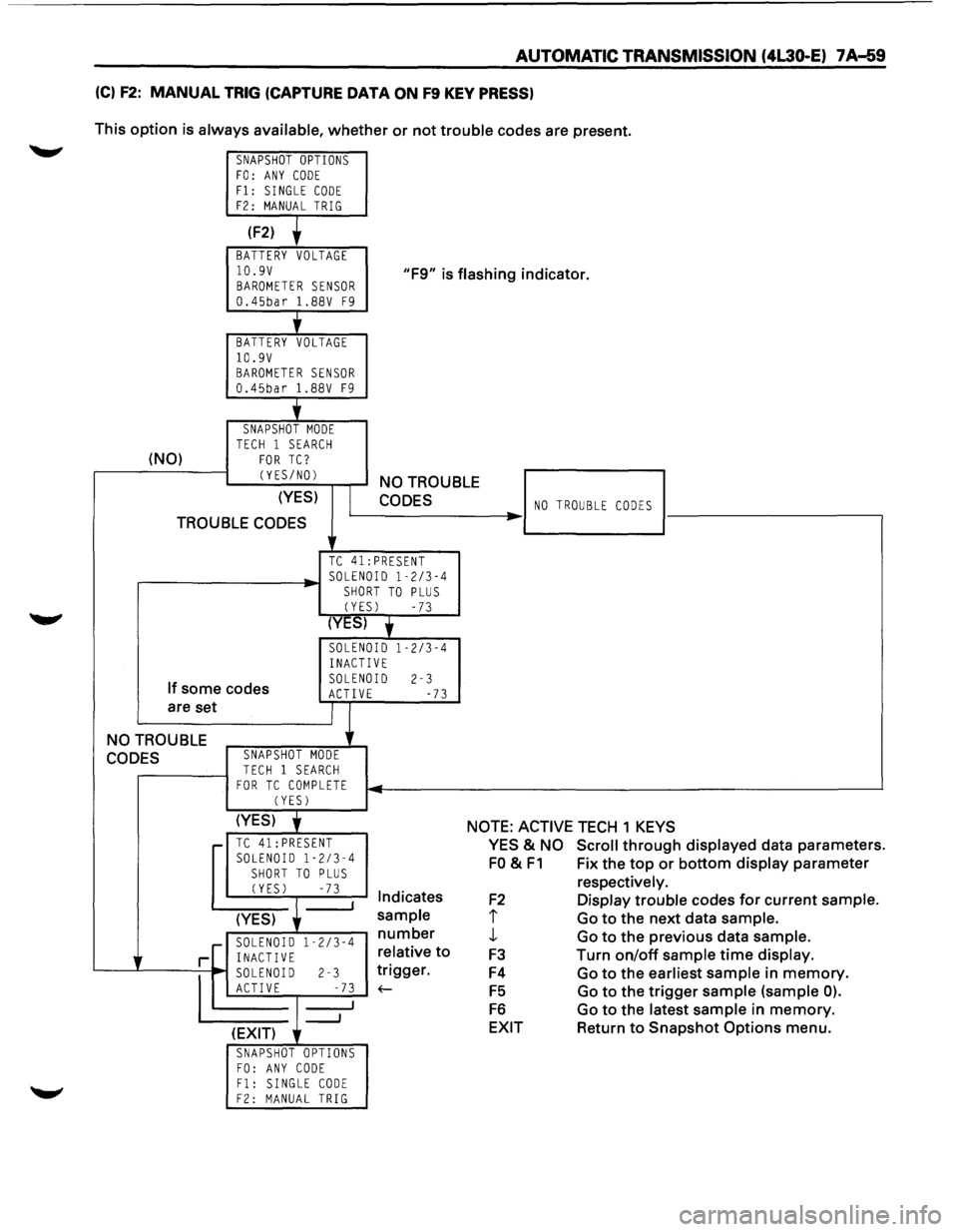
AUTOMATIC TRANSMISSION (4l30-E) 7A-59
(C) F2: MANUAL TRIG (CAPTURE DATA ON F9 KEY PRESS)
This option is always available, whether or not trouble codes are present.
SNAPSHOT OPTIONS FO: ANY CODE Fl: SINGLE CODE F2: MANUAL TRIG
(F2)
BATTERY VOLTAGE
10.9V BAROMETER SENSOR 0.45bar 1.88V F9
"F9" is flashing indicator.
'
BATTERY VOLTAGE 10.9V BAROMETER SENSOR 0.45bar 1.88V F9
j_
SNAPSHOT MODE TECH 1 SEARCH (NO) FOR TC?
CYES/NOl
(YES)
TROUBLE CODES
NO TROUBLE
CODES
TC 41:PRESENT
.----------~· SOLENOID 1-2/3-4 SHORT TO PLUS
CYESl -73
(YES) y
SOLENOID 1-2/3-4
INACTIVE
If some codes
are set SOLENOID 2-3 ACTIVE -73
NO TROUBLE
CODES SNAPSHOT MODE
TECH 1 SEARCH FOR TC COMPLETE CYESl
NO TROUBLE CODES ..
(YES) j NOTE: ACTIVE TECH 1 KEYS r-TC 41: PRESENT SOLENOID 1-2/3-4
SHORT TO PLUS CYESl -73 I Indicates
(YES)
sample
r--~~:--":'"~~ number
r[ i~~g~0~ 1 -2
/3
-4 relative
to
'---...L----=--
1
~ soLEN~ I-D r-------l-2 _-~...;.7.;;..3 1
__, ~gger.
(EXIT)
SNAPSHOT OPTIONS FO: ANY CODE Fl: SINGLE CODE F2: MANUAL TRIG
YES & NO Scroll through displayed data parameters.
FO & F1 Fix the top or bottom display parameter
F2
I
J,
F3
F4
F5
F6
EXIT
respectively.
Display trouble codes for current sample.
Go to the next data sample.
Go to the previous data sample.
Turn
on/off sample time display.
Go to the earliest sample in memory.
Go to the trigger sample (sample 0).
Go to the latest sample in memory.
Return to Snapshot Options menu.