ESP ISUZU TROOPER 1995 Service Manual
[x] Cancel search | Manufacturer: ISUZU, Model Year: 1995, Model line: TROOPER, Model: ISUZU TROOPER 1995Pages: 1928
Page 1622 of 1928
![ISUZU TROOPER 1995 Service Manual 98-38 CRUISE CONTROL
VEHICLE SPEED SENSOR (INCORPO
RATED IN SPEEDOMETER)
(1!] INSPECTION
GND GND
SEN 4P
~
I Red(+) Black(-) Black(-) Red(+)
a
I
4P GND 4P GND
4P-GND
13.5K-16.5K 00
Note:](/img/61/57183/w960_57183-1621.png "ISUZU TROOPER 1995 Service Manual 98-38 CRUISE CONTROL
VEHICLE SPEED SENSOR (INCORPO
RATED IN SPEEDOMETER)
(1!] INSPECTION
GND GND
SEN 4P
~
I Red(+) Black(-) Black(-) Red(+)
a
I
4P GND 4P GND
4P-GND
13.5K-16.5K 00
Note:")
98-38 CRUISE CONTROL
VEHICLE SPEED SENSOR (INCORPO
RATED IN SPEEDOMETER)
(1!] INSPECTION
GND GND
SEN 4P
~
I Red(+) Black(-) Black(-) Red(+)
a
I
4P GND 4P GND
4P-GND
13.5K-16.5K 00
Note: Use an analog type circuit tester.
Fig. 98-25
~~~ Removethespeedometerfromthemeterassem-DIODE
bly, and measure the resistance value between
the
terminals. (Fig. 98-26) IL•IINSPECTION
Replace the speedometer assembly when the
result of inspection is found abnormal.
B REMOVAL AND INSTALLATION
1•+1 Refer to Section 8 "METER AND WARNING/
INDICATOR LIGHT"
for vehicle speed sensor
removal and installation steps.
I B-451
~
Terminal No. 1 2
Connection A
G 0
pattern
0 G 8
Fig.
98-26
I~~ There should be continuity in either A or 8 when
a circuit tester is connected
with diode terminal.
(Fig. 98-26)
Replace the diode when the result of inspection
is
found abnormal.
..
Page 1632 of 1928
9J-8 Supplemental Restraint System
DEFINITIONS
AIR BAG -An inflatable cloth cushion designed to
deploy in certain frontal crashes. It supplements the
protection offered by the seat belts by distributing the
impact load more evenly over the vehicle occupant's
head and torso.
ASYNCHRONOUS -Performed in a non-periodic
fashion,i.e.no defined time or interval.
B+-Battery voltage, the voltage available at the battery
at the time of the indicated measurement. With the key
"ON" and the engine not running, the system voltage will
likely be between 12 and 12.5 volts. At idle the voltage
may be 14 to 16 volts. The voltage could be as low as 1
0
volts during engine cranking.
BULB
CHECK-The DERM will cause the "AIR BAG"
warning lamp to flash seven times and then go "OFF"
whenever the ignition switch transitions to the RUN
position from any other ignition switch position and no
malfunctions are detected.
"CONTINUOUS MONITORING"-Tests performed by
the DERM on the
SRS every 1 00 milliseconds while
"Ignition
1" voltage is in the normal operating voltage
range at the DERM.
DATA LINK CONNECTOR(DLC)-Formerly "ALDL'', a
connector which allows communication with an
off-board computer, such as a scan
tool.
DATUM LINE-A base line parallel to the plane of the
underbody or frame from which all vertical
measurements originate.
DEPLOY-To inflate the air bag.
DEPLOYMENT
LOOPS - The circuits which supply
current to the inflator modules to deploy the air bag.
DERM -Diagnostic
energy reserve module which
provides reserve energy to the deployment loops and
performs diagnostic monitoring of
all SRS components.
DIAGNOSTIC TROUBLE CODE(DTC) -Formerly
"Code,"a numerical designator used by the DERM to
indicate specific
SRS malfunctions.
DRIVER CURRENT SOURCE-An output of the DERM
which injects current into the driver inflator module circuit
during the "Initiator Assembly Resistance
Test."
DRIVER INFLATOR
MODULE-An assembly located in
the steering wheel hub consisting of an inflatable air bag,
an inflator and an initiator.
DUAL
POLE ARMING SENSOR-A sensor on the high
side(power side) of the deployment loops that is
calibrated to supply voltage to the inflator modules when
the vehicle velocity changes are severe enough to
warrant arming of the air bags in preparation for
deployment.
EEPROM -Electrically Erasable Programmable Read ~
Only Memory. Memory which retains its contents when
power
is removed from the DERM.
FORWARD LH DISCRIMINATING SENSOR-A sensor
on the low side(ground side) of the deployment loops
which is calibrated to ground the inflator modules when
the vehicle velocity changes are severe enough to
warrant deployment of the air bags.
FORWARD RH DISCRIMINATING SENSOR-A sensor
on the low side(ground side) of the deployment loops
which
is calibrated to ground the inflator modules when
the vehicle velocity changes are severe enough
to
warrant deployment of the air bag.
FORWARD LH SENSOR Eng-Room HARNESS-An
assembly of two correct carrying wires which connects
the Forward
LH discriminating sensor to SRS harness.
FORWARD RH SENSOR Eng-Room HARNESS
JUMPER-An assembly of two current carrying wires
which connects the Forward
RH discriminating sensor to
the
SRS harness.
HIGHER PRIORITY FAULT-Each diagnostic trouble
code
is assigned a priority based on the detectability with
other DTCs present. The priority corresponds to the
detectability of the malfunction ONLY, and does NOT
relate to the criticality of the malfunction with respect to ~
deployment or non-deployment under any given
condition.
IGNITION CYCLE -The voltage at the PERM "Ignition
1"
inputs, with ignition switch "ON," is within the normal
operating voltage range for at least ten seconds before
turning ignition switch
"OFF."
IGNITION1
-A battery voltage(B+)circuit which is only
powered with the ignition switch in the RUN,BULB
TEST,or START positions.
INITIATOR-The electrical component inside the inflator
module which, when sufficient current flows, sets off the
chemical reaction that inflates the air bag.
"INITIATOR ASSEMBLY RESISTANCE TEST"-Tests
performed once each ignition cycle when no
malfunctions are detected during "Turn-ON" or
"Continuous Monitoring." This test checks for the correct
DERM configuration for the vehicle, shorts to
"Ignition 1"
in the deployment loops, high resistance or opens in the
"Driver
Side High," "Driver Side Low," "Passenger Side
High"
and "Passenger Side Low" circuits and measures
the resistance of the inflator assembly consisting of: 1)
Initiators, 2) SRS coil assembly(driver side only), 3)
Connectors and associated wiring.
NORMAL OPERATING VOLTAGE RANGE-The ~
voltage measured between the DERM "Ignition 1" ·
terminals and "Ground" terminals is between 7.25 and 16
volts.
•
Page 1656 of 1928
9J-32 Supplemental Restraint System (SRS)
SRS DIAGNOSTIC SYSTEM CHECK
WARNING: TO AVOID DEPLOYMENT WHEN
TROUBLESHOOTING THE SRS, DO NOT USE
ELECTRICAL TEST EQUIPMENT SUCH AS A
BATTERY-POWERED OR AC-POWERED
VOLTMETER, OHMMETER, ETC., OR ANY TYPE OF
ELECTRICAL EQUIPMENT OTHER THAN THAT
SPECIFIED IN THIS MANUAL. DO NOT USE A
NON-POWERED PROBE TYPE TESTER.
INSTRUCTIONS IN THIS MANUAL MUST BE
FOLLOWED CAREFULLY, OTHERWISE PERSONAL
INJURY
MAY RESULT.
The diagnostic procedures used in this section are
designed to find and repair
SRS malfunctions. To get the
best results, it is important to use the diagnostic charts
and
follow the sequence listed below:
A. PERFORM THE "SRS DIAGNOSTIC SYSTEM
CHECK."
The "SRS Diagnostic System Check" must be the
starting point of any
SRS diagnostics. The "SRS
Diagnostic System Check" checks for proper "AIR
BAG"
warning lamp operation, the ability of the
DERM to communicate through the
"Serial Data" line
and whether SRS diagnostic trouble codes exist.
B. REFER TO THE PROPER DIAGNOSTIC CHART
AS
DIRECTED BY THE SRS DIAGNOSTIC
SYSTEM CHECK."
The "SRS Diagnostic System Check" will lead you to
the correct chart to diagnose any
SRS malfunctions.
Bypassing these procedures may result
in extended
diagnostic time, incorrect diagnosis and incorrect
parts replacement.
C. REPEAT THE "SRS DIAGNOSTIC SYSTEM
CHECK" AFTER ANY REPAIR OR DIAGNOSTIC
PROCEDURES HAVE
BEEN PERFORMED.
Performing
the "SRS Diagnostic System Check"
after all repair or diagnostic procedures will ensure
that the repair has been made correctly and that no
other malfunctions exist.
CIRCUIT DESCRIPTION
When the ignition switch is first turned "ON,""Ignition 1"
voltage is applied from the "C-22·C-23" fuse to the
DERM at the
"Ignition 1" input terminals "A9" and "A10"
and from the "C-21" fuse to the DERM at the "Redundant
Indicator Ignition 1" input terminal "B2". The DERM
responds by flashing the
"AIR BAG" warning lamp seven
times while performing tests on the
SRS.When the
engine is being cranked,
"Starter'' voltage is applied from
the
"C-1" fuse to the DERM at the "Crank" input terminal
"B10".The DERM responds by grounding the "SRS
Indicator"
output terminal "B 1" until "Starter" voltage is
removed from the "Crank" input. This results in the "AIR
BAG" warning lamp being "ON" steady during
cranking.After cranking, the DERM will flash the "AIR
BAG"
warning lamp six times and perform tests on the
SRS.
NOTES ON SYSTEM CHECK CHART ~
1. The "AIR BAG" warning lamp should flash seven
times after ignition is first turned
"ON."
2. The "AIR BAG" warning lamp should remain "ON"
steady during cranking.
3. When the "AIR BAG" warning lamp flashes four
times during
"Bulb Check" this indicates a
malfunction
in the redundant lamp driver circuitry.
These malfunctions are diagnosed by
DTC 62 chart.
4. After cranking, the "AIR BAG" warning lamp should
flash six times then go
"OFF."
5. Improper operation of the "AIR BAG" warning lamp
is indicated. This test differentiates a warning lamp
stays
"ON" condition from a warning lamp does not
come
"ON" condition.
6. This test checks for the proper operation of the
"Serial Data" line. This test will also determine
whether history diagnostic trouble codes are stored
and, if so, identify them.
7. This test checks for proper operation of the
"Serial
Data"
line. This test will also identify the stored
diagnostic trouble codes and
whether they are
current or history.
~
DIAGNOSTIC AIDS
The order in which diagnostic trouble codes are
diagnosed is very important. Failure to diagnose the
diagnostic trouble codes in the order specified may result
in extended diagnostic time, incorrect diagnosis and
incorrect parts replacement.
Page 1660 of 1928
9J-36 Supplemental Restraint System
TABLE B
"AIR BAG" WARNING LAMP COMES "ON" STEADY
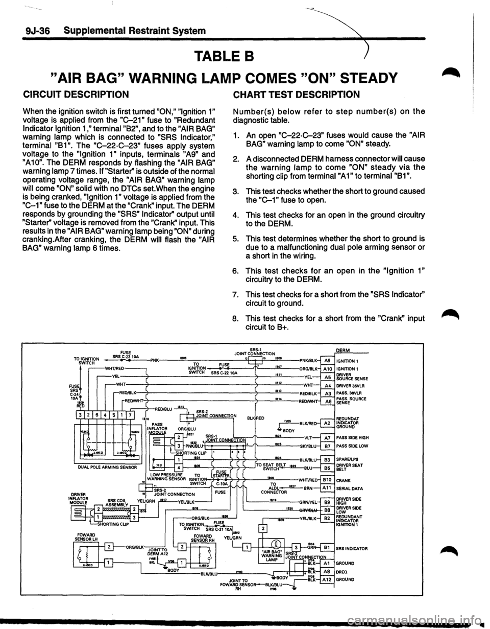
CIRCUIT DESCRIPTION
When the ignition switch is first turned "ON," "Ignition 1"
voltage is applied from the "C-21" fuse to "Redundant
Indicator Ignition 1 ,"terminal "B2", and to the "AIR BAG"
warning lamp which is connected to "SRS Indicator,"
terminal "B1". The "C-22·C-23" fuses apply system
voltage to the
"Ignition 1" inputs, terminals "A9" and
"A10". The DERM responds by flashing the "AIR BAG"
warning lamp 7 times. If "Starter" is outside of the normal
operating voltage range, the
"AIR BAG" warning lamp
will
come "ON" solid with no DTCs set. When the engine
is being cranked,
"Ignition 1" voltage is applied from the
"C-1" fuse to the DERM at the "Crank" input. The DERM
responds by grounding the
"SRS" Indicator" output until
"Starter" voltage is removed from the "Crank'' input. This
results in the
"AIR BAG" warning lamp being "ON" during
cranking.After cranking, the DERM
will flash the "AIR
BAG" warning lamp 6 times.
CHART TEST DESCRIPTION
Number(s) below refer to step number(s) on the
diagnostic table.
1. An open "C-22-C-23" fuses would cause the "AIR
BAG" warning lamp to come "ON" steady.
2. A disconnected DERM harness connector will cause
the warning
lamp to come "ON" steady via the
shorting clip from terminal "A1" to terminal "81".
3. This test checks whether the short to ground caused
the
"C-1" fuse to open.
4. This test checks for an open in the ground circuitry
to the DERM.
5. This test determines whether the short to ground is
due to a malfunctioning dual pole arming sensor or
a short
in the wiring.
6. This test checks for an open in the "Ignition 1"
circuitry to the DERM.
7. This test checks for a short from the "SRS Indicator''
circuit to ground.
8. This test checks for a short from the "Crank" input
circuit to 8+.
SRS-1 JOINT CONNECTION TO IGNITION FUSE SRS C·23 10A 1!015 '12 10 IGNITION I IGNITION 1 SWITCH
FUSE~ SRS C-24 10A .... R D
PASS.3eVLR PASS. SOURCE SENSE
PASS SlOE HIGH
PASS SlOE LOW
SERIAL DATA
SRS INDICATOR
..
Page 1662 of 1928
9J-38-~tal Restraint System
TABLE C
"AIR BAG" WARNING LAMP DOES NOT COME "ON"
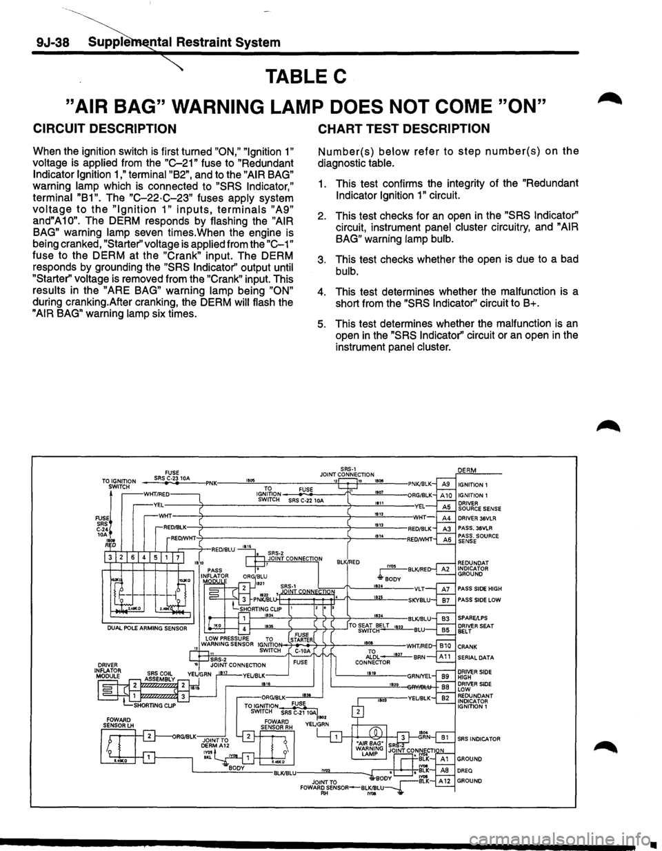
CIRCUIT DESCRIPTION
When the ignition switch is first turned "ON," "Ignition 1"
voltage is applied from the "C-21" fuse to "Redundant
Indicator Ignition 1 ,"terminal "B2", and to the "AIR BAG"
warning lamp which is connected to "SRS Indicator,"
terminal "B1".
The "C-22·C-23" fuses apply system
voltage to the "Ignition 1" inputs, terminals "A9"
and"A10". The DERM responds by flashing the "AIR
BAG"
warning lamp seven times.When the engine is
being cranked,
"Starter'' voltage is applied from the "C-1"
fuse to the DERM at the "Crank" input. The DERM
responds by grounding the
"SRS Indicator'' output until
"Starter" voltage
is removed from the "Crank" input. This
results in the "ARE BAG" warning lamp being "ON"
during cranking.After cranking, the DERM will flash the
"AIR BAG" warning lamp six times.
TO IGNITION
SWITCH
FUSEj
SRS C-24 10A-
1Bot RD
FUSE SRS C-23 10A ,. ..
CHART TEST DESCRIPTION
Number(s) below refer to step number(s) on the
diagnostic table.
1. This test confirms the integrity of the "Redundant
Indicator Ignition 1" circuit.
2. This test checks for an open in the "SRS Indicator"
circuit, instrument panel cluster circuitry, and "AIR
BAG"
warning lamp bulb.
3. This test checks whether the open is due to a bad
bulb.
4. This test determines whether the malfunction is a
short from the
"SRS Indicator'' circuit to B+.
5. This test determines whether the malfunction is an
open in the "SRS Indicator'' circuit or an open in the
instrument
panel cluster.
SRS-1 JOINT CONNECTION
1834
IGNITION 1 IGNITION 1 DRIVER SOURCE SENSE DRIVER 36VLR PASS. 36VLR
REDUNDAT
INDICATOR GROUND
PASS
SIDE HIGH
PASS
SIDE LOW
1---''""""'-------'l-----l--'1-~--'TO ~&'Jc~ELT 1833 BLU FUSE N-7-ST.,AR_TE.,_R+-'l---'1----"''"'"'-"---WHT/RED C-1 0A Al'6L ____.Jill_ BAN FUSE CONNECTOR 1819
1820
SERIAL DATA
DRIVER SIDE HIGH DRIVER SIDE LOW REDUNDANT INDICATOR
IGNITION 1
SRS INDICA TOR
•
Page 1664 of 1928
9J-40 Supplemental Restraint System
TABLED
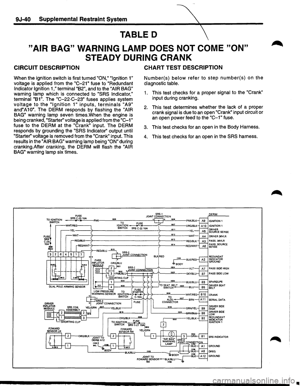
"AIR BAG" WARNING LAMP DOES NOT COME "ON"
STEADY DURING
CRANK
CIRCUIT DESCRIPTION
When the ignition switch is first turned "ON," "Ignition 1"
voltage is applied from the "C-21" fuse to "Redundant
Indicator Ignition
1 ,"terminal "B2", and to the "AIR BAG"
warning lamp which is connected to "SRS Indicator,"
terminal "B1". The "C-22-C-23" fuses applies system
voltage to the "Ignition 1" inputs, terminals "A9"
and"A10". The DERM responds by flashing the "AIR
BAG"
warning lamp seven times.When the engine is
being cranked,
"Starter'' voltage is applied from the "C-1"
fuse to the DERM at the "Crank" input. The DERM
responds by grounding the
"SRS Indicator'' output until
"Starter'' voltage is removed from the "Crank" input. This
results
in the "AIR BAG" warning lamp being "ON" during
cranking.After cranking, the DERM
will flash the "AIR
BAG"
warning lamp six times.
FUSE
CHART TEST DESCRIPTION
Number(s) below refer to step number(s) on the
diagnostic table.
1. This test checks for a proper signal to the "Crank"
input during cranking.
2. This test determines whether the lack of a proper
crank signal
is due to an open "Crank" input circuit or
an open power feed to the "C-1" fuse.
3. This test checks for an open in the Body Harness.
4. This test checks for an open in the SRS harness.
SRS-1
TO IGNITION SWITCH
JOINT CONNECTION ___ sR_S~C-·23~1-~---PNK.----~"~~------------~~~--~~~~---IGNITION1
IGNITION 1
FUSE~ SRS C-24 lOA loot R D
IGJ;~ION __ __.,;FU.:;.SE0------'!"------"'""""---------:1-----------S-W_IT_CH ___ SR_S_C-_22_1_DA ____ -7-----"'a"-'"-----YEL
IYOS BLK/RE
l"soDv
DRIVER 36VLR PASS. 36VLA PASS. SOURCE SENSE
REDUNDAT INDICATOR GROUND
PASS SIDE HIGH
PASS SIDE LOW
SERIAL DATA
DRIVER SIDE HIGH DRIVER SIDE LOW REDUNDANT INDICATOR IGNITION 1
SRS INDICATOR
•
Page 1684 of 1928
9J-60 Supplemental Restraint System
DTC 24 {PAGE 1 OF 3)
INITIATOR CIRCUIT VOLTAGE LOW
' I,
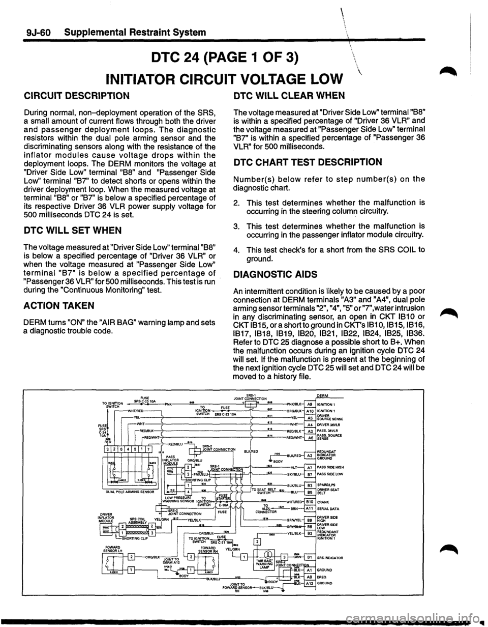
CIRCUIT DESCRIPTION
During normal, non-deployment operation of the SRS,
a small amount of current flows through both the driver
and passenger deployment loops. The diagnostic
resistors within the dual pole arming sensor and the
discriminating sensors
along with the resistance of the
inflator modules cause voltage drops within the
deployment loops. The DERM monitors the voltage at
"Driver Side Low" terminal "88" and "Passenger Side
Low" terminal "87" to detect shorts or opens within the
driver deployment
loop. When the measured voltage at
terminal "88" or "87" is below a specified percentage of
its respective Driver 36 VLR power
supply voltage for
500 milliseconds DTC 24 is set.
DTC WILL SET WHEN
The voltage measured at "Driver Side Low" terminal "88"
is below a specified percentage of "Driver 36 VLR" or
when the
voltage measured at "Passenger Side Low"
terminal "87" is below a specified percentage of
"Passenger 36 VLR" for 500 milliseconds. This test is run
during the "Continuous Monitoring" test.
ACTION TAKEN
DERM turns "ON" the "AIR BAG" warning lamp and sets
a diagnostic
trouble code.
DTC WILL CLEAR WHEN
The voltage measured at "Driver Side Low" terminal "88"
is within a specified percentage of "Driver 36 VLR" and
the
voltage measured at "Passenger Side Low" terminal
"87"
is within a specified percentage of "Passenger 36
VLR" for 500 milliseconds.
DTC CHART TEST DESCRIPTION
Number(s) below refer to step number(s) on the
diagnostic chart.
2. This test determines whether the malfunction is
occurring
in the steering column circuitry.
3. This test determines whether the malfunction is
occurring
in the passenger inflator module circuitry.
4. This test check's for a short from the SRS COIL to
ground.
DIAGNOSTIC AIDS
An intermittent condition is likely to be caused by a poor
connection at DERM terminals
"A3" and "A4", dual pole
arming sensor terminals "2", "4", "5" or"7",water intrusion
in any discriminating sensor, an open in CKT 1810 or
CKT 1815, ora short to ground in CKT's 1810,1815, 1816,
1817, 1818,
1819, 1820, 1821, 1822, 1824, 1825, 1836.
Refer to DTC 25 diagnose a possible short to B+. When
the malfunction occurs during
an ignition cycle DTC 24
will set. If the malfunction is present at the beginning of
the next ignition
cycle DTC 25 will set and DTC 24 will be
moved to a history
file.
SAS·1 JOINT CONNEC'TlON ,, .
PASS SIDE HIGH PASS SIDE LOW
SRS INDICATOR
Page 1686 of 1928
9J-62 Supplemental Restraint System
DTC 24 (PAGE 2 OF 3)
INITIATOR CIRCUIT VOLTAGE LOW
CIRCUIT DESCRIPTION
During normal, non-deployment operation of the SRS,
a small amount of current flows through both the driver
and
passenger deployment loops. The diagnostic
resistors within the dual pole arming sensor and the
discriminating sensors
along with the resistance of the
inflator modules cause voltage drops within the
deployment loops. The DERM monitors the voltage at
"Driver
Side Low" terminal "88" and "Passenger Side
Low" terminal "87"
to detect shorts or opens within the
driver deployment
loop. When the measured voltage at
terminal "88" or "87" is below a specified percentage of
its respective Driver 36 VLR power
supply voltage for
500 milliseconds DTC 24 is set.
DTC WILL SET WHEN
The voltage measured at "Driver Side Low'' terminal "88"
is below a specified percentage of "Driver 36 VLR" or
when the
voltage measured at "Passenger Side Low"
terminal "87" is below a specified percentage of
"Passenger 36 VLR" for 500 milliseconds. This test is run
during the "Continuous Monitoring" test.
ACTION TAKEN
DERM turns "ON" the "AIR BAG" warning lamp and sets
a diagnostic
trouble code.
""
DTC WILL CLEAR WHEN
The voltage measured at "Driver Side Low" terminal "88"
is within a specified percentage of "Driver 36 VLR" and
the
voltage measured at "Passenger Side Low" terminal
"87"
is within a specified percentage of "Passenger 36
VLR" for 500 milliseconds.
DTC CHART TEST DESCRIPTION
Number(s) below refer to step number(s) on the
diagnostic chart.
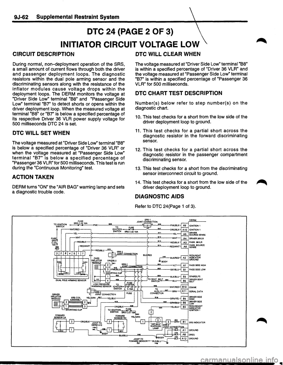
10. This test checks for a short from the low side of the
driver deployment
loop to ground.
11. This test checks for a partial short across the
diagnostic resistor in the forward discriminating
sensor.
12.
This test checks for a partial short across the
diagnostic resistor in the passenger compartment
discriminating sensor.
13. This test checks for a short from the discriminating
sensor interconnect circuit to ground.
14. This test checks for a short from the
low side of the
driver deployment
loop to ground.
DIAGNOSTIC AIDS
Refer to DTC 24(Page 1 of 3).
SRS-1 JOINT CONNECTION 1 10 180& IGNITION 1 IGNITION 1 DRIVER SOURCE SENSE DRIVER 36VLR PASS. 38VLR PASS. SOURCE SENSE
AEOUNDAT INotCATOR GROUND
PASS SlOE HIGH PASS SIDE LOW
SPARE/LPS
SERIAL DATA
SRS INDICATOR
Page 1688 of 1928
 \
INITIATOR CIRCUIT VOLTAGE LOW
CIRCUIT DESCRIPTION
During normal, non-deployment operation of the SRS,
a small amount of current")
9J-64 Supplemental Restraint System
DTC 24 {PAGE 3 OF 3) \
INITIATOR CIRCUIT VOLTAGE LOW
CIRCUIT DESCRIPTION
During normal, non-deployment operation of the SRS,
a small amount of current flows through both the driver
and passenger deployment loops. The diagnostic
resistors within the dual pole arming sensor and the
discriminating sensors along with the resistance of the
inflator modules cause voltage drops within the
deployment loops. The DERM monitors the voltage at
"Driver Side Low" terminal "88" and "Passenger Side
Low"
terminal "87" to detect shorts or opens within the
driver deployment loop. When the measured voltage at
terminal
"88" or "87" is below a specified percentage of
its respective Driver 36 VLR for
500 milliseconds DTC 24
is set.
DTC WILL SET WHEN
The voltage measured at "Driver Side Low'' terminal "88"
is below a specified percentage of "Driver 36 VLR" or
when the voltage measured at "Passenger
Side Low"
terminal "87" is below a specified percentage of
"Passenger 36 VLR" for 500 milliseconds. This test is run
during the "Continuous Monitoring" test.
ACTION TAKEN
DERM turns "ON" the "AIR BAG" warning lamp and sets
a diagnostic trouble code.
DTC WILL CLEAR WHEN
The voltage measured at "Driver Side Low" terminal "88"
is within a specified percentage of "Driver 36 VLR" and
the voltage measured at "Passenger
Side Low" terminal
"87" is within a specified percentage of "Passenger 36
VLR" for 500 milliseconds.
DTC CHART TEST DESCRIPTION
Number(s) below refer to step number(s) on the
diagnostic chart.
22. This test determines whether the malfunction is a
short from the high side of the passenger
deployment loop to ground. ·
23This test determines whether the malfunction is a
short from the high side of the Driver deployment
loop to ground.
24. This test checks for an open in the driver deployment
loop diagnostic resistor
of the dual pole arming
sensor.
25. This
test checks for an open in the passenger
deployment for an open in the passenger
deployment loop diagnostic resistor of the dual pole
arming sensor.
26. This test checks for high resistance in the "Driver 36
VLR" circuit.
27.
This test checks for high resistance in the
"Passenger 36 VLR" circuit.
28.
This test checks for high side of the driver
deployment loop.
29. This test checks for
an open in the high side of the
passenger deployment loop.
DIAGNOSTIC AIDS
Refer to DTC 24(Page 1 of 3).
Page 1696 of 1928
9J-72 Supplemental Restraint System
DTC28
CURRENT SINK OR SOURCE FAILURE
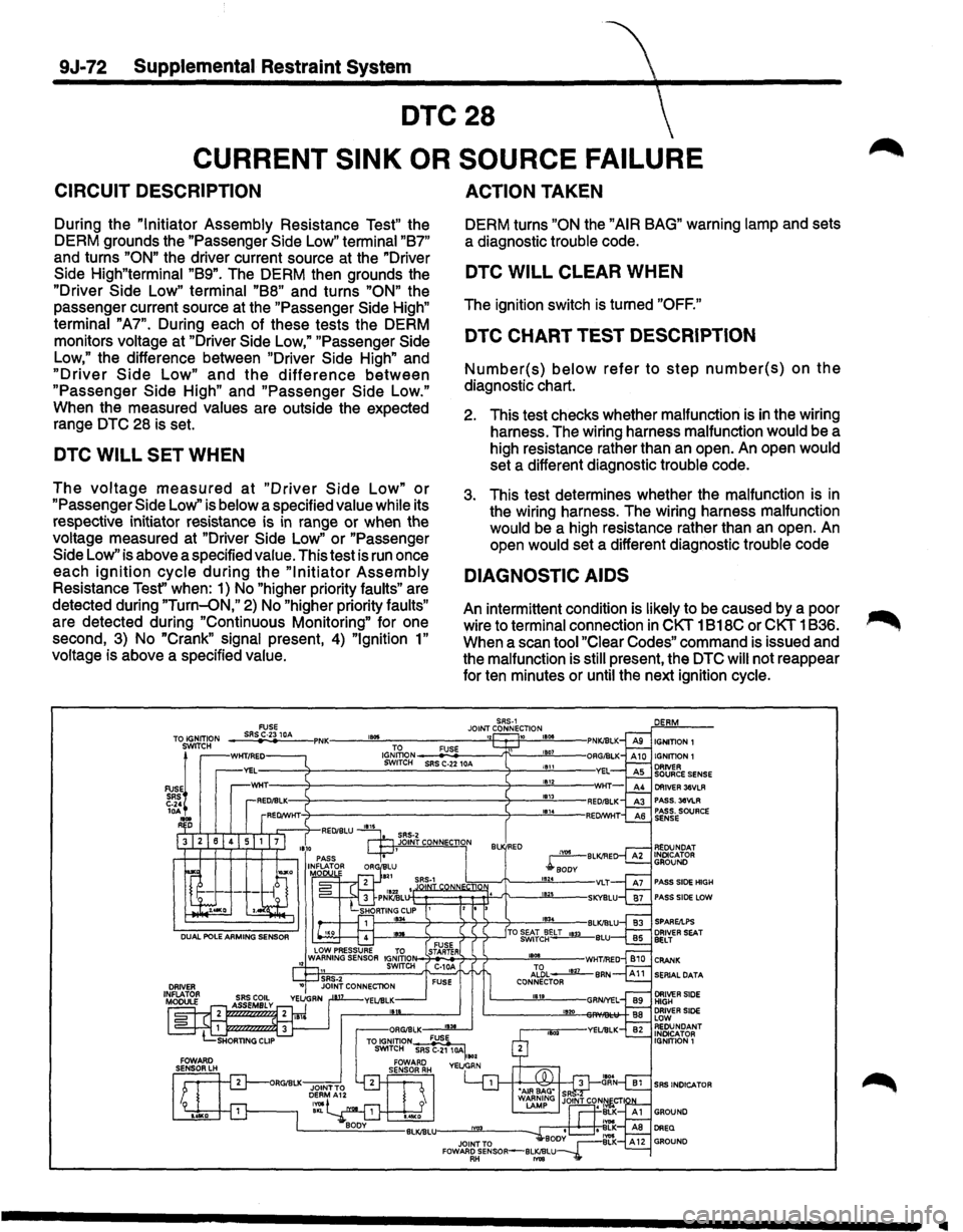
CIRCUIT DESCRIPTION
During the "Initiator Assembly Resistance Test" the
DERM grounds the "Passenger Side Low" terminal
"87"
and turns "ON" the driver current source at
the "Driver
Side High"terminal "89". The DERM then grounds the
"Driver Side Low" terminal
"88" and turns "ON" the
passenger current source at the "Passenger Side High"
terminal "A7". During each of these tests the DERM
monitors voltage at "Driver Side Low," "Passenger Side
Low," the difference between "Driver Side High" and
"Driver Side Low" and the difference between
"Passenger Side High" and "Passenger Side Low."
When the measured values are outside the expected
range DTC 28 is set.
DTC WILL SET WHEN
The voltage measured at "Driver Side Low" or
"Passenger Side Low'' is below a specified value while its
respective initiator resistance is
in range or when the
voltage measured at "Driver Side
Low" or "Passenger
Side Low" is above a specified value. This test is
run once
each
ignition cycle during the "Initiator Assembly
Resistance Tesf' when: 1) No "higher priority faults" are
detected during
"Turn-oN," 2) No "higher priority faults"
are detected during "Continuous Monitoring" for one
second, 3) No
"Crank" signal present, 4) "Ignition 1"
voltage is above a specified value.
, ...
ACTION TAKEN
DERM turns "ON the "AIR BAG" warning lamp and sets
a diagnostic trouble code.
DTC WILL CLEAR WHEN
The ignition switch is turned "OFF."
DTC CHART TEST DESCRIPTION
Number(s) below refer to step number(s) on the
diagnostic chart.
2. This test checks whether malfunction is in the wiring
harness. The wiring harness malfunction would be a
high resistance rather than an open. An open would
set a different diagnostic trouble code.
3. This test determines whether the malfunction is in
the wiring harness. The wiring harness malfunction
would be a high resistance rather than an open.
An
open would set a different diagnostic trouble code
DIAGNOSTIC AIDS
An intermittent condition is likely to be caused by a poor
wire to terminal connection
in CKT 1 B18C or CKT 1836.
When a scan tool
"Clear Codes" command is issued and
the malfunction is still present, the DTC will not reappear
for ten minutes or until the next ignition cycle.
SRS-1 JOINT CONNECTION 10 11508
IGJ~oN-_;F,:::U:;SE~--t\:__-!!£'"'L-SWITCH SRS C-22 10A 11511 1812 181l
Bl RED
IIIII