change wheel ISUZU TROOPER 1995 User Guide
[x] Cancel search | Manufacturer: ISUZU, Model Year: 1995, Model line: TROOPER, Model: ISUZU TROOPER 1995Pages: 1928
Page 325 of 1928
HYDRAULIC BRAKES 5A-5
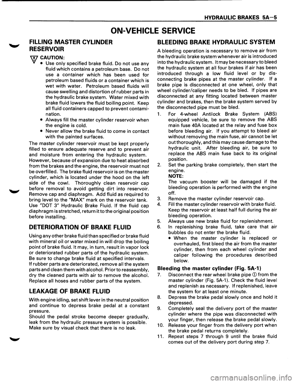
ON-VEHICLE SERVICE
FILLING MASTER CYLINDER
RESERVOIR
'\fl CAUTION:
'VI • Use only specified brake fluid. Do not use any
fluid which contains a petroleum base. Do not
use a container which has been used for
petroleum based fluids or a container which is
wet with water. Petroleum based fluids will
cause swelling and distortion of rubber parts in
the
hydraulic brake system. Water mixed with
brake fluid lowers the fluid boiling point. Keep
all fluid containers capped to prevent contami
nation.
• Always fill the master cylinder reservoir when
the engine is
cold.
•
Never allow the brake fluid to come in contact
with the painted surfaces.
The master
cylinder reservoir must be kept properly
filled
to ensure adequate reserve and to prevent air
and moisture
from entering the hydraulic system.
However, because
of expansion due to heat absorbed
from the brakes and the engine, the reservoir must not
be overfilled. The brake fluid reservoir is on the master
cylinder, which is located under the hood on the
left
side of the cowl. Thoroughly clean reservoir cap
before
removal to avoid getting dirt into reservoir.
Remove cap and diaphragm.
Add fluid as required to
bring level to the "MAX" mark on the reservoir tank.
Use
"DOT 3" Hydraulic Brake Fluid. If the fluid cap
diaphragm is stretched, return
it to the original position
before
installing.
DETERIORATION OF BRAKE FLUID
Using any other brake fluid than specified or brake fluid
with mineral oil or water mixed in will drop the boiling
point of brake fluid. It may, in turn, result in vapor lock
or deteriorated rubber parts of the hydraulic system.
Be sure to change brake fluid at specified intervals.
If rubber parts are deteriorated, remove all the system
parts and
clean them with alcohol. Prior to reassembly,
dry the cleaned parts with air to remove the alcohol.
Replace all
hoses and rubber parts of the system.
LEAKAGE OF BRAKE FLUID
With engine idling, set shift lever in the neutral position
and continue to depress brake
pedal at a constant
pressure.
Should the pedal stroke become deeper gradually,
leak from the hydraulic pressure system is possible.
Make sure
by visual check that there is no leak.
BLEEDING BRAKE HYDRAULIC SYSTEM
A bleeding operation is necessary to remove air from
the hydraulic brake system whenever air is introduced
into the hydraulic system.
It may be necessary to bleed
the hydraulic system at all four brakes if air has been
introduced through a
low fluid level or by dis
connecting brake pipes at the master cylinder. If a
brake pipe is disconnected at one
wheel, only that
wheel cylinder/caliper needs to be bled. If pipes are
disconnected at any fitting
located between master
cylinder and brakes, then the brake system served by
the disconnected pipe must
be bled.
1. For 4-wheel Antilock Brake System (ABS)
equipped
vehicle, be sure to remove the ABS
main fuse
40A located at the relay and fuse box
before
bleeding air. If you attempt to bleed air
without removing the main fuse, air cannot be let
out thoroughly, and this may cause damage to the
hydraulic unit.
After bleeding air, be sure to
replace the ABS main fuse back to its original
position.
2. Set the parking brake completely, then start the
engine.
NOTE:
The vacuum booster will be damaged if the
bleeding operation is performed with the engine
off.
3. Remove the master cylinder reservoir cap.
4. Fill the master cylinder reservoir with brake fluid.
Keep the reservoir at least half full during the air
bleeding operation.
5. Always use new brake fluid for replenishment.
6. In replenishing brake fluid, take care that air
bubbles do not enter the brake fluid.
•
When the master cylinder is replaced or
overhauled, first bleed the air from the master
cylinder, then from each
wheel cylinder and
caliper following the procedures described
below.
Bleeding the master cylinder (Fig. 5A-1}
7. Disconnect the rear wheel brake pipe
cylinder (Fig. 5A-1 ). Check the fluid level
and replenish as necessary. If replenished, leave
the system for at least one minute.
8. Depress the brake pedal slowly once and hold it
depressed.
9. Completely seal the delivery port of the master
cylinder where the pipe was disconnected with
your finger, then release the brake pedal slowly.
10. Release your finger from the delivery port when
the brake
pedal returns completely.
11. Repeat steps 7 through 9 until the brake fluid
comes out of the delivery port during step 7.
Page 414 of 1928
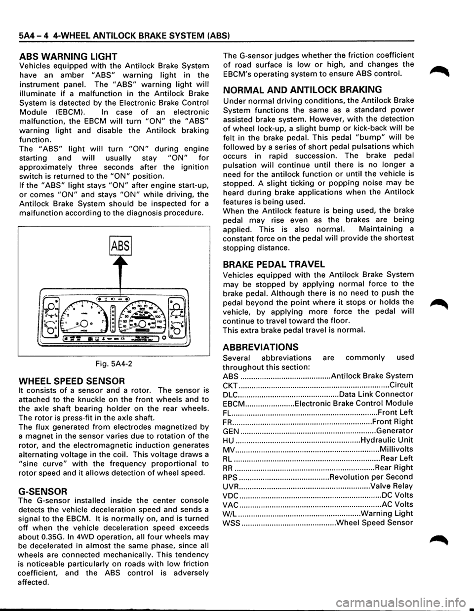
5A4-4 4-WHEEL ANTILOCK BRAKE SYSTEM (ABS)
ABS WARNING LIGHT
Vehicles equipped with the Antilock Brake System
have an
amber "ABS" warning light in the
instrument panel. The "ABS" warning light will
illuminate if a malfunction in the Antilock Brake
System is detected by the Electronic Brake
Control
Module (EBCM). In case of an electronic
malfunction, the EBCM will turn "ON" the "ABS"
warning light and disable the Antilock braking
function.
The
"ABS" light will turn "ON" during engine
starting and
will usually stay "ON" for
approximately three seconds after the ignition
switch is returned to the "ON" position.
If the "ABS" light stays "ON" after engine start-up,
or comes "ON" and stays "ON" while driving, the
Antilock Brake System should be inspected
for a
malfunction according to the diagnosis procedure.
Fig. 5A4-2
WHEEL SPEED SENSOR
It consists of a sensor and a rotor. The sensor is
attached
to the knuckle on the front wheels and to
the axle shaft bearing holder on the rear wheels.
The
rotor is press-fit in the axle shaft.
The
flux generated from electrodes magnetized by
a magnet in the sensor varies due to rotation of the
rotor, and the electromagnetic
induction generates
alternating voltage in
the coil. This voltage draws a
"sine curve" with the frequency proportional to
rotor speed and it allows detection of wheel speed.
G-SENSOR
The G-sensor installed inside the center console
detects the vehicle deceleration speed and sends a
signal
to the EBCM. It is normally on, and is turned
off when the vehicle deceleration speed exceeds
about 0.35G.
In 4WD operation, all four wheels may
be decelerated in almost the same phase, since all
wheels are connected mechanically. This tendency
is noticeable particularly on roads
with low friction
coefficient, and the
ABS control is adversely
affected. The
G-sensor judges
whether the friction coefficient
of road surface is low or high, and changes the
EBCM's operating system to ensure ABS control.
NORMAL AND ANTILOCK BRAKING
Under normal driving conditions, the Antilock Brake
System functions the same
as a standard power
assisted brake system. However, with the detection
of wheel lock-up, a slight bump or kick-back will be
felt in the brake pedal. This pedal
"bump" will be
followed by a series of short pedal pulsations which
occurs in rapid succession. The brake pedal
pulsation
will continue until there is no longer a
need
for the antilock function or until the vehicle is
stopped. A
slight ticking or popping noise may be
heard
during brake applications when the Antilock
features is being used.
When the
Antilock feature is being used, the brake
pedal
may rise even as the brakes are being
applied. This is also
normal. Maintaining a
constant force on the pedal
will provide the shortest
stopping distance.
BRAKE PEDAL TRAVEL
Vehicles equipped with the Antilock Brake System
may be stopped by applying normal force to the
brake pedal.
Although there is no need to push the
pedal beyond the
point where it stops or holds the ~
vehicle, by applying more force the pedal will
continue to travel toward the floor.
This extra brake pedal travel is normal.
ABBREVIATIONS
Several abbreviations are commonly used
throughout this section:
ABS .......................................... Antilock Brake System
CKT ...................................................................... Circuit
DLC ............................................... Data Link Connector
EBCM ....................... Eiectronic Brake Control Module
FL. ................................................................... Front Left
FR ................................................................. Front Right
GEN ............................................................... Generator
HU .......................................................... Hydraulic Unit
MV ................................................................... Millivolts
RL .................................................................... Rear Left
RR ................................................................. Rear Right
RPS .......................................... Revolution per Second
UVR ............................................................. Valve Relay
VDC .................................................................. DC Volts
VAC .................................................................. AC Volts
W/L .........................................................
Warning Light
WSS ............................................ Wheel Speed Sensor
Page 426 of 1928
5A4-16 4-WHEEL ANTILOCK BRAKE SYSTEM (ABS)
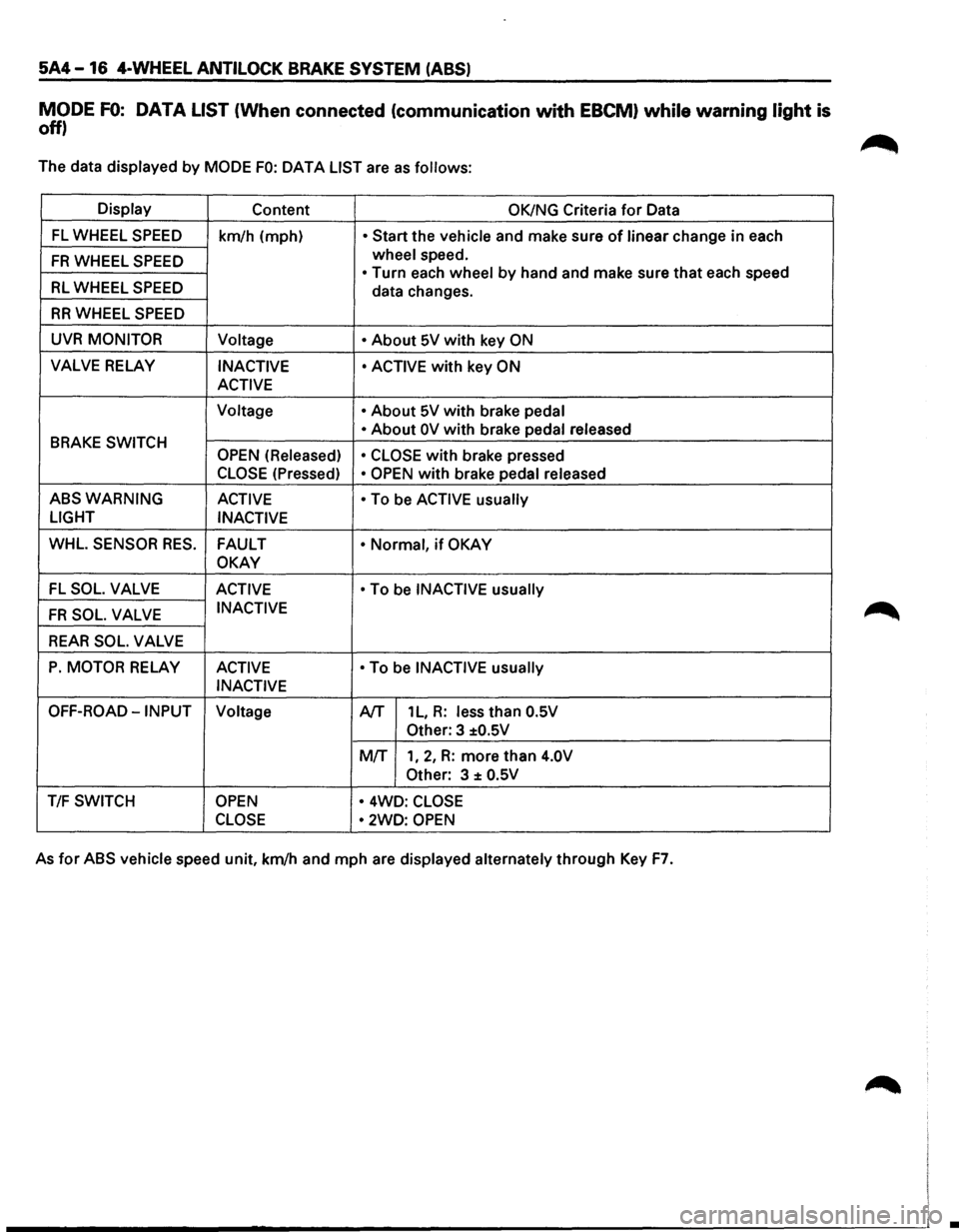
MODE FO: DATA LIST (When connected (communication with EBCM) while warning light is
off)
The data displayed by MODE FO: OAT A LIST are as follows:
Display Content OK/NG Criteria for Data
FL WHEEL SPEED km/h (mph) • Start the vehicle and make sure of linear change in each
FR WHEEL SPEED wheel speed.
• Turn each wheel by hand and make sure that each speed RL WHEEL SPEED data changes.
RR WHEEL SPEED
UVR MONITOR
Voltage • About 5V with key ON
VALVE RELAY INACTIVE • ACTIVE with key ON
ACTIVE
Voltage •
About 5V with brake pedal
BRAKE SWITCH • About OV with brake pedal
released
OPEN (Released)
• CLOSE
with brake pressed
CLOSE (Pressed) • OPEN with brake pedal released
ABSWARNING ACTIVE
• To be ACTIVE usually
LIGHT
INACTIVE
WHL. SENSOR RES. FAULT • Normal, if OKAY
OKAY
-FL SOL. VALVE ACTIVE • To be INACTIVE usually
FR SOL. VALVE INACTIVE
REAR SOL. VALVE
P. MOTOR RELAY ACTIVE • To be INACTIVE usually
INACTIVE
OFF-ROAD-INPUT Voltage A/T 1 L, R: less than O.SV
Other: 3 ±O.SV
MIT 1, 2, R: more than 4.0V
Other:
3 ± O.SV
T/F SWITCH OPEN • 4WD: CLOSE
CLOSE •
2WD: OPEN
As for ABS vehicle speed unit, km/h and mph are displayed alternately through Key F7.
•
Page 427 of 1928
4-WHEEL ANTILOCK BRAKE SYSTEM (ABS) 5A4-17
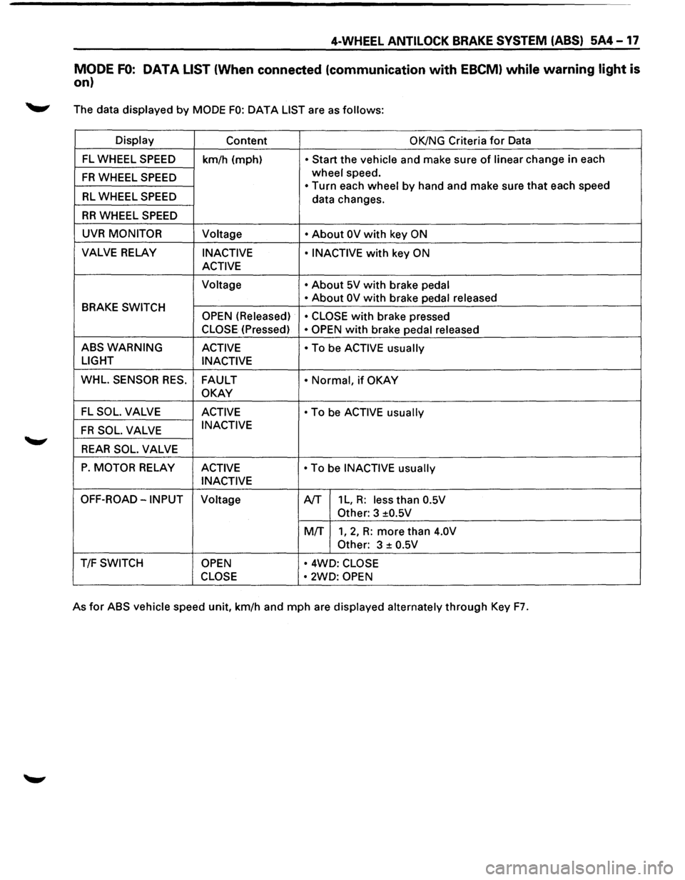
MODE FO: DATA LIST (When connected (communication with EBCM) while warning light is
on)
._,. The data displayed by MODE FO: DATA LIST are as follows:
Display
Content OK/NG Criteria for Data
FL WHEEL SPEED
km/h (mph) • Start the vehicle and make sure of linear change in each
FR WHEEL SPEED wheel speed.
• Turn each wheel by hand and make sure that each speed RL WHEEL SPEED data changes.
RR WHEEL SPEED
UVR MONITOR Voltage • About OV with key ON
VALVE RELAY INACTIVE • INACTIVE with key ON
ACTIVE
Voltage • About 5V with brake pedal
BRAKE
SWITCH • About OV with brake
pedal released
OPEN (Released) • CLOSE with brake pressed
CLOSE (Pressed) • OPEN with brake pedal released
ABSWARNING ACTIVE • To be ACTIVE usually
LIGHT
INACTIVE
WHL.
SENSOR RES. FAULT • Normal, if OKAY
OKAY
FL SOL. VALVE ACTIVE • To be ACTIVE usually
FR SOL. VALVE INACTIVE
REAR SOL. VALVE
P. MOTOR RELAY
ACTIVE • To be INACTIVE usually
INACTIVE
OFF-ROAD-INPUT Voltage A/T 1 L, R: less than 0.5V
Other:
3 ±0.5V
MIT
1, 2, R: more than 4.0V
Other:
3 ± 0.5V
T/F SWITCH OPEN • 4WD: CLOSE
CLOSE •
2WD: OPEN
As for ABS vehicle speed unit, km/h and mph are displayed alternately through Key F7.
Page 433 of 1928
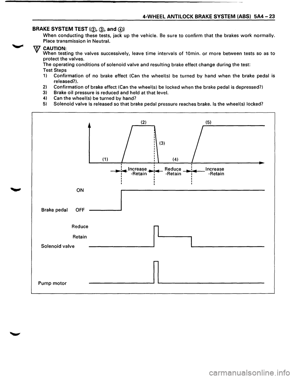
4-WHEEL ANTILOCK BRAKE SYSTEM (ABS) 5A4-23
BRAKE
SYSTEM TEST (®, @, and @)
When conducting these tests, jack up the vehicle. Be sure to confirm that the brakes work normally.
Place transmission
in Neutral.
\V CAUTION: When testing the valves successively, leave time intervals of 10min. or more between tests so as to
protect the valves.
The operating conditions
of solenoid valve and resulting brake effect change during the test:
Test
Steps
1) Confirmation of no brake effect (Can the wheel(s) be turned by hand when the brake pedal is
released?).
2) Confirmation of brake effect (Can the wheel(s) be locked when the brake pedal is depressed?)
3) Brake oil pressure is reduced and held at that level.
4) Can the wheel(s) be turned by hand?
5) Solenoid valve is released so that brake pedal pressure reaches brake. Is the wheel(s) locked?
(2) (5)
I
(3)
(1) (4) I
I
..,. ;.,.. lncrea~e ..,.1.,.. Reduce I Increase ... : ... 1 -Retam 1 -Retain I -Retain I I I
I I I
I I I
I I I
ON
Brake
pedal OFF
Reduce
r
Retain
I Solenoid valve
Pump
motor ~
Page 442 of 1928
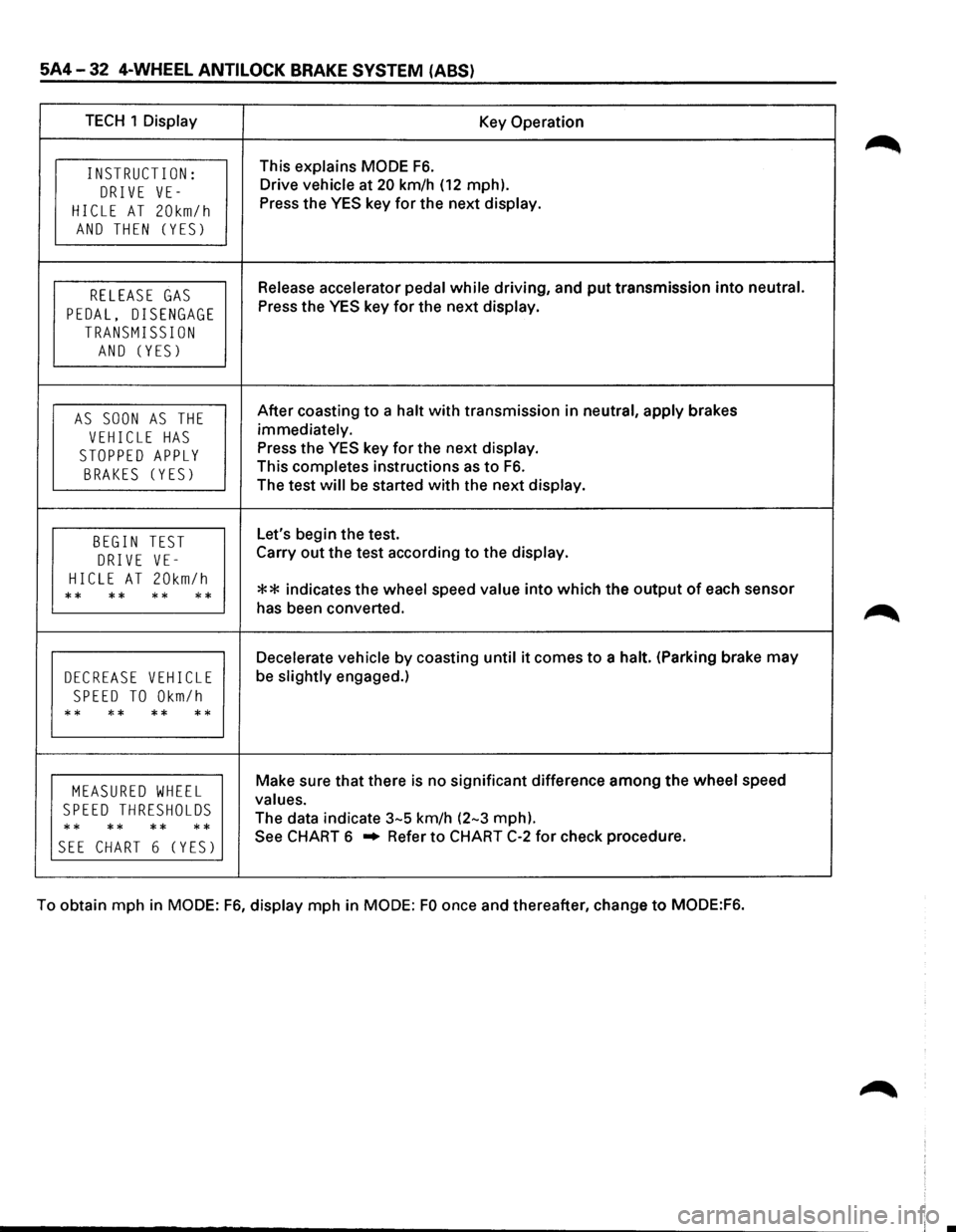
5A4-32 4-WHEEL ANTI LOCK BRAKE SYSTEM (ABS)
TECH 1 Display Key Operation
INSTRUCT I ON: This explains MODE F6.
DRIVE VE-Drive vehicle at 20 km/h (12 mph).
HICLE AT 20km/h Press the YES key for the next display.
AND THEN (YES)
RELEASE GAS Release accelerator pedal while driving, and put transmission into neutral.
PEDAL, DISENGAGE Press the YES key for the next display.
TRANSMISSION
AND (YES)
AS SOON AS THE After coasting to a halt with transmission in neutral, apply brakes
VEHICLE HAS immediately.
STOPPED APPLY Press the YES key for the next display.
BRAKES (YES) This completes instructions as to F6.
The test will be started with the next display.
BEGIN TEST Let's begin the test.
DRIVE VE-Carry out the test according to the display.
HICLE AT 20km/h ** indicates the wheel speed value into which the output of each sensor ** ** ** ** has been converted.
Decelerate vehicle by coasting until it comes to a halt. (Parking brake may
DECREASE VEHICLE be slightly engaged.)
SPEED TO Okm/h
** ** ** **
MEASURED WHEEL Make sure that there is no significant difference among the wheel speed
SPEED THRESHOLDS values.
** **
** ** The
data indicate 3-5 km/h (2-3 mph).
SEE CHART 6 (YES) See CHART 6 .. Refer to CHART C-2 for check procedure.
To obtain mph in
MODE: F6, display mph in MODE: FO once and thereafter, change to MODE:F6.
Page 473 of 1928
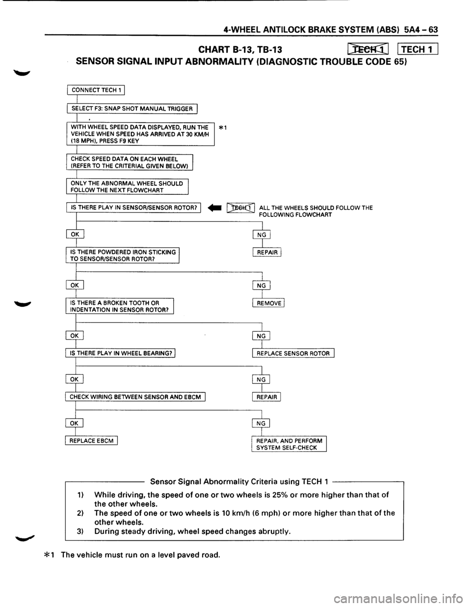
CHART B-13, TB-13 l)EeR:[I I TECH 1 I
SENSOR SIGNAL INPUT ABNORMALITY (DIAGNOSTIC TROUBLE CODE 65)
SELECT F3: SNAP SHOT MANUAL TRIGGER
WITH
WHEEL SPEED DATA DISPLAYED, RUN THE *1 VEHICLE WHEN SPEED HAS ARRIVED AT 30 KM/H
(18 MPH), PRESS F9 KEY
CHECK SPEED DATA ON EACH WHEEL (REFER TO THE CRITERIAL GIVEN BELOW)
ONLY THE ABNORMAL WHEEL SHOULD
FOLLOW THE NEXT FLOWCHART
IS THERE PLAY IN SENSOR/SENSOR ROTOR? -I)Eel{[l ALL THE WHEELS SHOULD FOLLOW THE FOLLOWING FLOWCHART
IS THERE POWDERED IRON STICKING
TO SENSOR/SENSOR ROTOR?
cill
~
Sensor Signal Abnormality Criteria using TECH 1 --------,
1) While driving, the speed of one or two wheels is 25% or more higher than that of
the other wheels.
2) The speed of one or two wheels is 10 km/h (6 mph) or more higher than that of the
other
wheels.
3) During steady driving, wheel speed changes abruptly.
* 1 The vehicle must run on a level paved road.
Page 742 of 1928
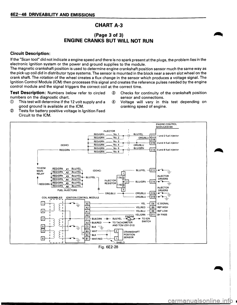
6E2-46 DRIVEABILITV AND EMISSIONS
CHART A-3
(Page 3 of 3)
ENGINE CRANKS BUT WILL NOT RUN
Circuit Description:
If the "Scan tool" did not indicate a engine speed and there is no spark present at the plugs, the problem lies in the
electronic ignition system
or the power and ground supplies to the module.
The magnetic crankshaft position is used to determine engine crankshaft position sensor much the same way as
the pick-up coil did in distributor type systems. The sensor is mounted in the block near a seven slot wheel on the
crank shaft. The rotation
of the wheel creates a flux change in the sensor which produces a voltage signal. The
Ignition Control Module (ICM) then processes this signal and creates the reference pulses needed by the engine
control module and the signal triggers the correct coil at the correct time.
Test Description: Numbers below refer to circled ® Checks for continuity of the crankshaft position
numbers on the diagnostic chart. sensor and connections.
available at the ICM. cranking speed of engine.
® Tests for battery positive voltage in Ignition Feed
Circuit to the
ICM.
TO ECM RED/GRN #1 BLU/YEL MAIN RELAY
tRED/GRN
RED/GRN #2 BLU/YEL
RED/GRN #3 BLU/YEL
RED/GRN '"#4 BLU/YEL RED/GRN #5 BLU/YEL RED/GRN #6 BLU/YEL
FUEL
INJECTORS INJECTOR
RED/GRN RED/GRN RED/GRN
E"'QINE YELJGRN D11 BLK!ORN ----)>--BLK!YEL _____..,-~ TO IGN BLK!RED
-TO TACHOMETER SWITCH BLK --:::J_ AND TCM (C91-D12)
WHT2cl]= :-·-, 2 CRANKSHAFT BLK ~ : POSITION WHT/RED · __ ,' 1 SENSOR
'-;SHIELD
Fig. 6E2-28
ENGINE CONTROL
MODULEIECM)
1 and 2 fuel injector
•
Page 827 of 1928
DRIVEABILITY AND EMISSIONS 6E2-131
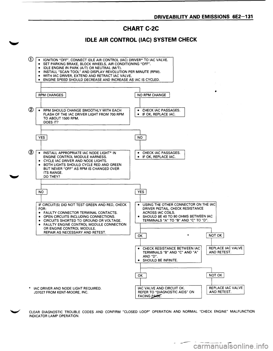
CHART C-2C
IDLE AIR CONTROL (lAC) SYSTEM CHECK
CD • IGNITION "OFF", CONNECT IDLE AIR CONTROL (lAC) DRIVER* TO lAC VALVE. • SET PARKING BRAKE, BLOCK WHEELS, AIR CONDITIONING "OFF".
• IDLE ENGINE IN PARK (A/T) OR NEUTRAL (MIT). • INSTALL "SCAN TOOL" AND DISPLAY REVOLUTION PER MINUTE (RPM). • WITH lAC DRIVER, EXTEND AND RETRACT lAC VALVE. • ENGINE SPEED SHOULD DECREASE AND INCREASE AS lAC IS CYCLED.
I
1 I • RPM CHANGES I NO RPM CHANGE I
I I • RPM SHOULD CHANGE SMOOTHLY
WITH EACH • CHECK lAC PASSAGES.
I FLASH OF THE lAC DRIVER LIGHT FROM 700 RPM • IF OK, REPLACE lAC.
TO ABOUT 1500 RPM. DOES IT?
I
~ cf
• INSTALL APPROPRIATE lAC NODE LIGHT* IN • CHECK lAC PASSAGES.
l ENGINE CONTROL MODULE HARNESS. • IF OK, REPLACE lAC. ®
• CYCLE lAC
DRIVER AND NODE LIGHTS.
• BOTH LIGHTS SHOULD CYCLE RED AND GREEN BUT NEVER "OFF" AS RPM IS CHANGED OVER
ITS RANGE. DO THEY?
I
cf ~ IF CIRCUIT(S) DID NOT TEST GREEN AND RED, CHECK •
USING THE OTHER CONNECTOR ON THE lAC
FOR: DRIVER
PIGTAIL, CHECK RESISTANCE
•
FAULTY CONNECTOR TERMINAL CONTACTS. ACROSS
lAC COILS.
• OPEN CIRCUITS INCLUDING CONNECTIONS. •
SHOULD BE 40 TO 80 OHMS BETWEEN lAC
• CIRCUITS SHORTED TO GROUND OR VOLTAGE. TERMINALS "A" TO "B" AND "C" TO "D".
• FAULTY ENGINE CONTROL MODULE CONNECTION I OR ENGINE CONTROL MODULE.
~
l REPAIR AS NECESSARY AND RETEST. l NOT OK I .
_l
• CHECK RESISTANCE BETWEEN lAC I REPLACE lAC VALVE I TERMINALS "B" AND "C" AND "A" AND RETEST. AND "D". • SHOULD BE INFINITE.
I
~
l
I NOT OK I
]
AC DRIVER AND NODE LIGHT REQUIRED. * I J lAC VALVE AND CIRCUIT OK. I REPLACE lAC VALVE J 37027 FROM KENT-MOORE, INC. REFER TO "DIAGNOSTIC AIDS" ON AND RETEST. FACING~
~ CLEAR DIAGNOSTIC TROUBLE CODES AND CONFIRM "CLOSED LOOP" OPERATION AND NORMAL "CHECK ENGINE" MALFUNCTION
INDICATOR LAMP OPERATION.
------
Page 834 of 1928
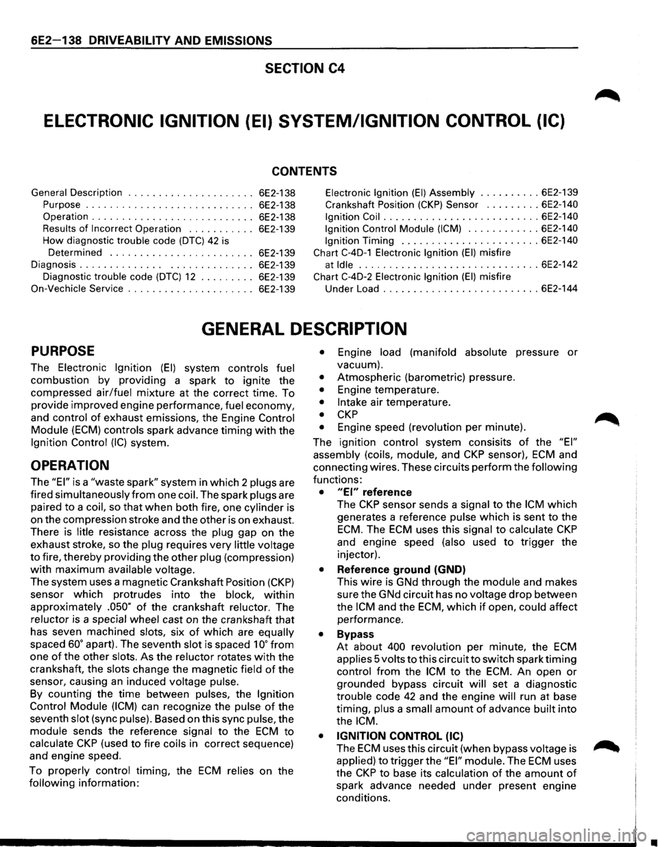
6E2-138 DRIVEABILITY AND EMISSIONS
SECTION C4
ELECTRONIC IGNITION (EI) SYSTEM/IGNITION CONTROL (IC)
CONTENTS
General Description . . . . . . . . . . . . . . . . . . . . . 6E2-138
Purpose
............................ 6E2-138
Operation
........................... 6E2-138
Results of Incorrect Operation . . . . . . . . . . . 6E2-139
How diagnostic trouble code (DTC) 42 is
Determined ........................ 6E2-139
Diagnosis. . . . . . . . . . . . . . . ............. 6E2-139
Diagnostic
trouble code (DTC) 12 . . . . . . . . . 6E2-139
On-Vechicle Service . .
. . . . . . . . . . . . . . . . . . . 6E2-139
Electronic Ignition (EI) Assembly .......... 6E2-139
Crankshaft Position (CKP) Sensor ......... 6E2-140
Ignition Coil
.......................... 6E2-140
Ignition Control
Module (ICM) ............ 6E2-140
Ignition
Timing ....................... 6E2-140
Chart
C-4D-1 Electronic Ignition (EI) misfire
at
Idle .............................. 6E2-142
Chart C-4D-2 Electronic Ignition (EI) misfire
Under Load .......................... 6E2-144
GENERAL DESCRIPTION
PURPOSE
The Electronic Ignition (EI) system controls fuel
combustion by providing a spark to ignite the
compressed
air/fuel mixture at the correct time. To
provide improved engine performance,
fuel economy,
and
control of exhaust emissions, the Engine Control
Module
(ECM) controls spark advance timing with the
Ignition Control (IC) system.
OPERATION
The "EI" is a "waste spark" system in which 2 plugs are
fired
simultaneously from one coil. The spark plugs are
paired
to a coil, so that when both fire, one cylinder is
on the compression stroke and the other is on exhaust.
There is
Iitie resistance across the plug gap on the
exhaust stroke, so the
plug requires very little voltage
to fire, thereby providing the other plug (compression)
with maximum available voltage.
The system uses a magnetic Crankshaft Position (CKP)
sensor which protrudes into the block, within
approximately .050" of the crankshaft reluctor. The
reluctor is a special wheel cast on the crankshaft that
has seven machined
slots, six of which are equally
spaced 60° apart). The seventh slot is spaced 1 oo from
one
of the other slots. As the reluctor rotates with the
crankshaft, the
slots change the magnetic field of the
sensor, causing
an induced voltage pulse.
By counting the time between pulses, the Ignition
Control Module (ICM)
can recognize the pulse of the
seventh
slot (sync pulse). Based on this sync pulse, the
module sends the reference signal to the ECM to
calculate CKP (used to fire coils in correct sequence)
and engine speed.
To
properly control timing, the ECM relies on the
following information:
• Engine load (manifold absolute pressure or
vacuum).
• Atmospheric (barometric) pressure.
• Engine temperature.
• Intake air temperature.
• CKP
• Engine speed (revolution per minute).
The ignition
control system consisits of the "EI"
assembly (coils, module,
and CKP sensor), ECM and
connecting wires. These circuits
perform the following
functions:
• "EI" reference
The CKP sensor sends a signal to the ICM which
generates a reference
pulse which is sent to the
ECM. The ECM uses this signal to calculate CKP
and engine speed (also used to trigger the
injector).
• Reference ground (GND)
This wire is GNd through the module and makes
sure the GNd circuit has no
voltage drop between
the
ICM and the ECM, which if open, could affect
performance.
• Bypass
At about 400 revolution per minute, the ECM
applies 5 volts to this circuit to switch spark timing
control from the ICM to the ECM. An open or
grounded bypass circuit
will set a diagnostic
trouble code 42 and the engine will run at base
timing,
plus a small amount of advance built into
the
ICM.
• IGNITION CONTROL (IC)
The ECM uses this circuit (when bypass voltage is
applied) to trigger the "EI" module. The ECM uses
the
CKP to base its calculation of the amount of
spark advance needed under present engine
conditions.
•