change wheel ISUZU TROOPER 1995 Owner's Manual
[x] Cancel search | Manufacturer: ISUZU, Model Year: 1995, Model line: TROOPER, Model: ISUZU TROOPER 1995Pages: 1928
Page 892 of 1928
7 A-20 AUTOMATIC TRANSMISSION (4L30-E)
CHECKING TRANSMISSION FLUID
LEVEL AND CONDITION
Checking fluid level and condition (color and odor)
at
regular intervals will provide early diagnosis
information about the transmission. This inform
ation may be used to correct a condition that, if not
detected early, could result in major transmission
repairs.
IMPORTANT: When new, automatic transmission
fluid is red in color. As the vehicle is driven, the
transmission
fluid will begin to look darker in color.
The
color may eventually appear light brown.
A DARK
brown color with burnt odor may indicate
excessive
fluid deterioration and signal a need for
fluid change.
FLUID LEVEL
When adding
or changing fluid, use only DEXRON
®-Ill.
Refer to the Maintenance and Lubrication (Section 0
of this manual) for maintenance information and
servicing
interval.
\f CAUTION: DO NOT OVERFILL
Overfilling will cause foaming, loss ~f fluid,
abnormal shifting and possible damage to
the transmission.
1. Start engine and drive vehicle until normal AfT
oil operating temperature is reached:
NOTE: The automatic transmission fluid level
must be checked with the vehicle at normal
A/T oil operating temperature: 75 TO 85°C
(167 TO 185°F) MEASURED WITH TECH1 SCAN
TOOL.
Temperature will greatly affect transmission
fluid level.
If the vehicle is not at normal AfT oil operating
temperature and the proper checking
procedures are
not followed, the result could
be a false reading of the fluid level indicator
and
an incorrect adjustment of the fluid level.
2. Park vehicle on level ground.
3. Move gear selector to "Park".
4. Apply parking brake and block wheels.
5. Allow vehicle to idle for 3 minutes with all
accessories turned off.
6. Check fluid level with engine running at idle:
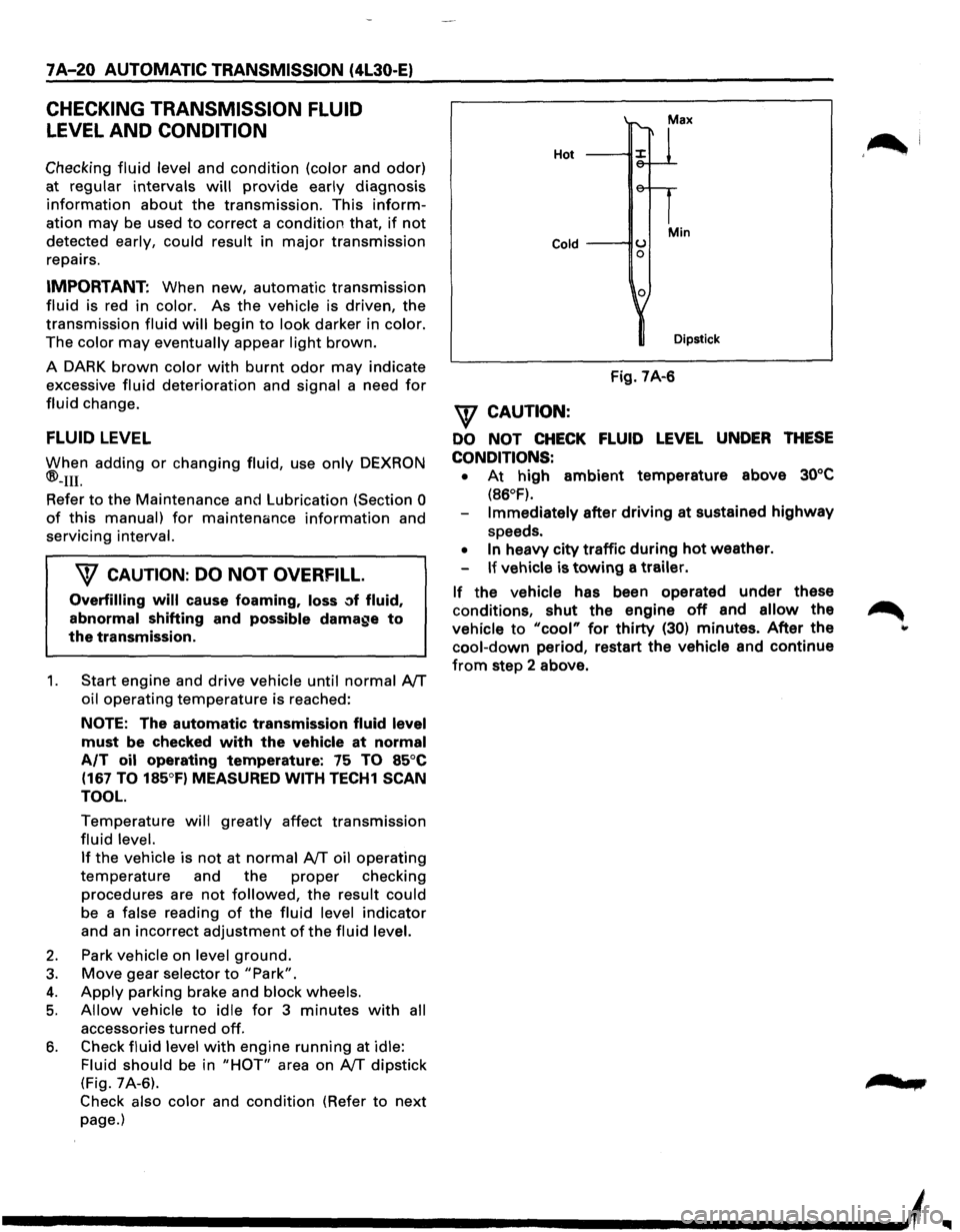
Fluid should
be in "HOT" area on AfT dipstick
(Fig. 7A-6).
Check also color and condition (Refer to next
page.)
Hot
Cold ---IIU 0
0
Min
Dipstick
Fig. 7A-6
\f CAUTION:
DO NOT CHECK FLUID LEVEL UNDER THESE
CONDITIONS: •
At high ambient temperature above 30°C
(86°F).
Immediately after driving at sustained highway
speeds.
• In heavy city traffic during hot weather.
If vehicle is towing a trailer.
If the vehicle has been operated under these
conditions,
shut the engine off and allow the
vehicle to "cool" for thirty (30) minutes. After the
cool-down period, restart the vehicle and continue
from step 2 above.
'~I
......
Page 1006 of 1928
7A-134 AUTOMATIC TRANSMISSION (4L30-E)
DIAGNOSTIC TROUBLE CODE (DTC) 62
DOWNSHIFT PROTECTION
This DTC flashes the CHECK TRANS indicator and
sets the
BACKUP MODE.
Circuit Description:
• The output speed information is used to
determine if the transmission has to upshift or
downshift.
• If this information suddenly changes due to an
open circuit or some electrical interference the
transmission
would downshift.
• To avoid this the Transmission Control Module
(TCM) is constantly checking the variations of the
Output Speed. If this variation is too great (too
much decrease
or increase) DTC62 is set. This
variation is taken into
amount only when the
output speed is more than : 90 KPH.
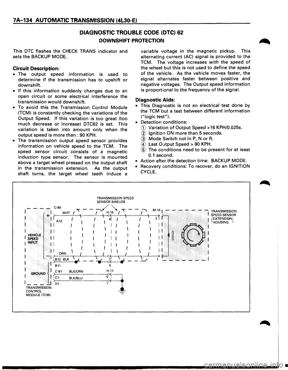
• The transmission output speed sensor provides
information on vehicle speed to the TCM. The
speed sensor circuit consists
of a magnetic
induction
type sensor. The sensor is mounted
above a target wheel pressed on the output shaft
in the transmission extension. As the
output
shaft turns, the target wheel teeth induce a
TRANSMISSION SPEED SENSOR SHIELDS
variable voltage in the magnetic pickup. This
alternating current (AC) signal is provided to the
TCM. The
voltage increases with the speed of
the wheel but this is not used to define the speed
of the vehicle. As the vehicle moves faster, the
signal alternates faster between positive and
negative
voltages. The Output speed information
is proportiional to the frequency of the signal.
Diagnostic Aids:
• This Diagnostic is not an electrical test done by
the TCM but a test between different information
("logic test").
• Detection conditions:
G) Variation of Output Speed >16 KPH/0.025s.
@ Ignition ON more than 5 seconds.
@ Mode Switch not in P, N or R.
@ Last Output Speed > 90 KPH.
@ The conditions need to be present for at least
0.1 second.
• Action after the detection time: BACKUP MODE.
•
Recovery Gonditions: To recover, do an IGNITION
CYCLE.
- - - -C-90 / " I ,---:-"'\. '-. ~---+I WHT I I I I ~-10 I 'I I 'I M-1
5 r - - - - - - -TRANSMISSION ) f I SPEED SENSOR I . I f A 12 I I I I ~ I I I I
I II I I I I I I I I I
I II I I I I 1 I I
~~~~rie II I Ill I I
IINPUT II I I I I
1 1 1 I l I I I I -? ORN I I < I I
I l: ):~~ BLK \~ __ ~~ __ ~
I GROUNO I C-91 BLK/ORN H-11
I I I C1 BLK/BLU ~ 9_ I ____ I D1
TRANSMISSION
CONTROL MODULE (TCM)
2 I I (EXTENSION)
: : .·(C},h.·.. ,.·, .. ·.,· .. : HOUSING
II II ·<;',~ . I
I I . 'I ' . . I
I I I
) I> 1 ________ I
•
Page 1093 of 1928
MANUAL TRANSMISSION 78-3
DIAGNOSIS
Problem Possible cause Correction
•
Flywheel pilot bearing worn Replace
•
Bearings worn or broken (Mainshaft, counter shaft, and Replace
transfer shaft)
Abnormal noise • Gear tooth contact surfaces worn or scuffed (Mainshaft, Replace
counter shaft, reverse idler gear and transfer gears)
• Splines worn (Mainshaft, synchronizer clutch hub) Replace
•
Gear or bearing thrust face seized Replace
•
Lack of backlash between meshing gears Replace
• Improper clutch pedal
free play Readjust
• Change lever sliding portions worn Repair or replace
Regrease
• Shift block, shift rod and/or control box sliding faces Replace
Hard Shifting worn
• Shift arm and synchronizer sleeve groove worn Replace worn parts
• Thrust washer, collar, and/or gear thrust faces worn Replace worn parts
(Mainshaft and counter shaft thrust
play)
•
Synchronizer parts worn Replace
•
Detent ball worn Replace
•
Detent spring weakened or broken Replace
Walking
or • Shift rod and/or control box sliding faces worn Replace
Jumping out of • Shift arm and synchronizer sleeve groove worn Replace worn parts
gear
• Thrust washer, collar, and/or gear thrust faces worn Replace worn parts
(Mainshaft and counter shaft thrust
play)
•
Bearings worn or broken Replace
• Splines
worn (Mainshaft, synchronizer hub) Replace
•
Synchronizer spring weakened or broken Replace
•
Loose drain plug(s) and/or filler plug(s) Tighten
Oil leakage Replenish
oil
• Defective or improperly installed gasket(s) Replace
• Oil seal
worn or scratched Replace
Page 1632 of 1928
9J-8 Supplemental Restraint System
DEFINITIONS
AIR BAG -An inflatable cloth cushion designed to
deploy in certain frontal crashes. It supplements the
protection offered by the seat belts by distributing the
impact load more evenly over the vehicle occupant's
head and torso.
ASYNCHRONOUS -Performed in a non-periodic
fashion,i.e.no defined time or interval.
B+-Battery voltage, the voltage available at the battery
at the time of the indicated measurement. With the key
"ON" and the engine not running, the system voltage will
likely be between 12 and 12.5 volts. At idle the voltage
may be 14 to 16 volts. The voltage could be as low as 1
0
volts during engine cranking.
BULB
CHECK-The DERM will cause the "AIR BAG"
warning lamp to flash seven times and then go "OFF"
whenever the ignition switch transitions to the RUN
position from any other ignition switch position and no
malfunctions are detected.
"CONTINUOUS MONITORING"-Tests performed by
the DERM on the
SRS every 1 00 milliseconds while
"Ignition
1" voltage is in the normal operating voltage
range at the DERM.
DATA LINK CONNECTOR(DLC)-Formerly "ALDL'', a
connector which allows communication with an
off-board computer, such as a scan
tool.
DATUM LINE-A base line parallel to the plane of the
underbody or frame from which all vertical
measurements originate.
DEPLOY-To inflate the air bag.
DEPLOYMENT
LOOPS - The circuits which supply
current to the inflator modules to deploy the air bag.
DERM -Diagnostic
energy reserve module which
provides reserve energy to the deployment loops and
performs diagnostic monitoring of
all SRS components.
DIAGNOSTIC TROUBLE CODE(DTC) -Formerly
"Code,"a numerical designator used by the DERM to
indicate specific
SRS malfunctions.
DRIVER CURRENT SOURCE-An output of the DERM
which injects current into the driver inflator module circuit
during the "Initiator Assembly Resistance
Test."
DRIVER INFLATOR
MODULE-An assembly located in
the steering wheel hub consisting of an inflatable air bag,
an inflator and an initiator.
DUAL
POLE ARMING SENSOR-A sensor on the high
side(power side) of the deployment loops that is
calibrated to supply voltage to the inflator modules when
the vehicle velocity changes are severe enough to
warrant arming of the air bags in preparation for
deployment.
EEPROM -Electrically Erasable Programmable Read ~
Only Memory. Memory which retains its contents when
power
is removed from the DERM.
FORWARD LH DISCRIMINATING SENSOR-A sensor
on the low side(ground side) of the deployment loops
which is calibrated to ground the inflator modules when
the vehicle velocity changes are severe enough to
warrant deployment of the air bags.
FORWARD RH DISCRIMINATING SENSOR-A sensor
on the low side(ground side) of the deployment loops
which
is calibrated to ground the inflator modules when
the vehicle velocity changes are severe enough
to
warrant deployment of the air bag.
FORWARD LH SENSOR Eng-Room HARNESS-An
assembly of two correct carrying wires which connects
the Forward
LH discriminating sensor to SRS harness.
FORWARD RH SENSOR Eng-Room HARNESS
JUMPER-An assembly of two current carrying wires
which connects the Forward
RH discriminating sensor to
the
SRS harness.
HIGHER PRIORITY FAULT-Each diagnostic trouble
code
is assigned a priority based on the detectability with
other DTCs present. The priority corresponds to the
detectability of the malfunction ONLY, and does NOT
relate to the criticality of the malfunction with respect to ~
deployment or non-deployment under any given
condition.
IGNITION CYCLE -The voltage at the PERM "Ignition
1"
inputs, with ignition switch "ON," is within the normal
operating voltage range for at least ten seconds before
turning ignition switch
"OFF."
IGNITION1
-A battery voltage(B+)circuit which is only
powered with the ignition switch in the RUN,BULB
TEST,or START positions.
INITIATOR-The electrical component inside the inflator
module which, when sufficient current flows, sets off the
chemical reaction that inflates the air bag.
"INITIATOR ASSEMBLY RESISTANCE TEST"-Tests
performed once each ignition cycle when no
malfunctions are detected during "Turn-ON" or
"Continuous Monitoring." This test checks for the correct
DERM configuration for the vehicle, shorts to
"Ignition 1"
in the deployment loops, high resistance or opens in the
"Driver
Side High," "Driver Side Low," "Passenger Side
High"
and "Passenger Side Low" circuits and measures
the resistance of the inflator assembly consisting of: 1)
Initiators, 2) SRS coil assembly(driver side only), 3)
Connectors and associated wiring.
NORMAL OPERATING VOLTAGE RANGE-The ~
voltage measured between the DERM "Ignition 1" ·
terminals and "Ground" terminals is between 7.25 and 16
volts.
•