engine ISUZU TROOPER 1995 User Guide
[x] Cancel search | Manufacturer: ISUZU, Model Year: 1995, Model line: TROOPER, Model: ISUZU TROOPER 1995Pages: 1928
Page 24 of 1928
OB-8 MAINTENANCE AND LUBRICATION
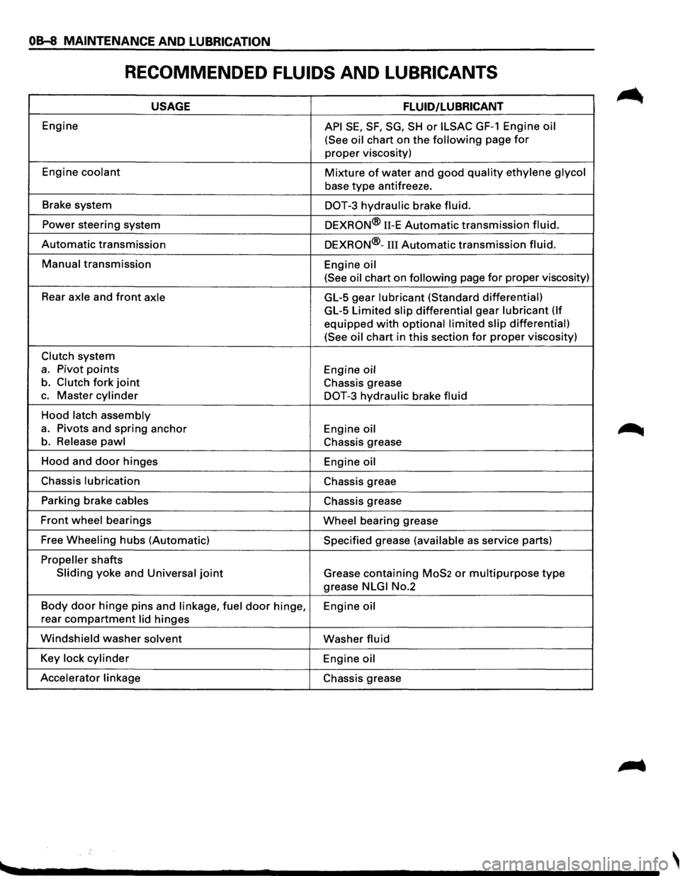
RECOMMENDED FLUIDS AND LUBRICANTS
USAGE FLUID/LUBRICANT
Engine API SE, SF, SG, SH or ILSAC GF-1 Engine oil
(See oil
chart on the following page for
proper viscosity)
Engine
coolant Mixture of water and good quality ethylene glycol
base type antifreeze.
Brake system
DOT-3 hydraulic brake fluid.
Power steering system
DEXRON® 11-E Automatic transmission fluid.
Automatic transmission DEXRON®-III Automatic transmission fluid.
Manual transmission
Engine oil
(See oil
chart on following page for proper viscosity)
Rear
axle and front axle GL-5 gear lubricant (Standard differential)
GL-5 Limited slip differential gear lubricant (If
equipped with optional limited slip differential)
(See oil
chart in this section for proper viscosity)
Clutch system
a. Pivot points Engine oil
b. Clutch fork joint Chassis grease
c. Master cylinder DOT-3 hydraulic brake fluid
Hood latch assembly
a. Pivots and spring anchor
Engine oil
b. Release pawl Chassis grease
Hood and
door hinges
Engine oil
Chassis lubrication Chassis greae
Parking brake
cables Chassis grease
Front wheel bearings Wheel bearing grease
Free
Wheeling hubs (Automatic) Specified grease (available as service parts)
Propeller shafts
Sliding yoke and Universal joint Grease containing MoS2 or multipurpose type
grease NLGI No.2
Body
door hinge pins and linkage, fuel door hinge,
Engine oil
rear compartment lid hinges
Windshield washer solvent Washer fluid
Key lock cylinder Engine oil
Accelerator linkage
Chassis grease
Page 25 of 1928
MAINTENANCE AND LUBRICATION 08-9
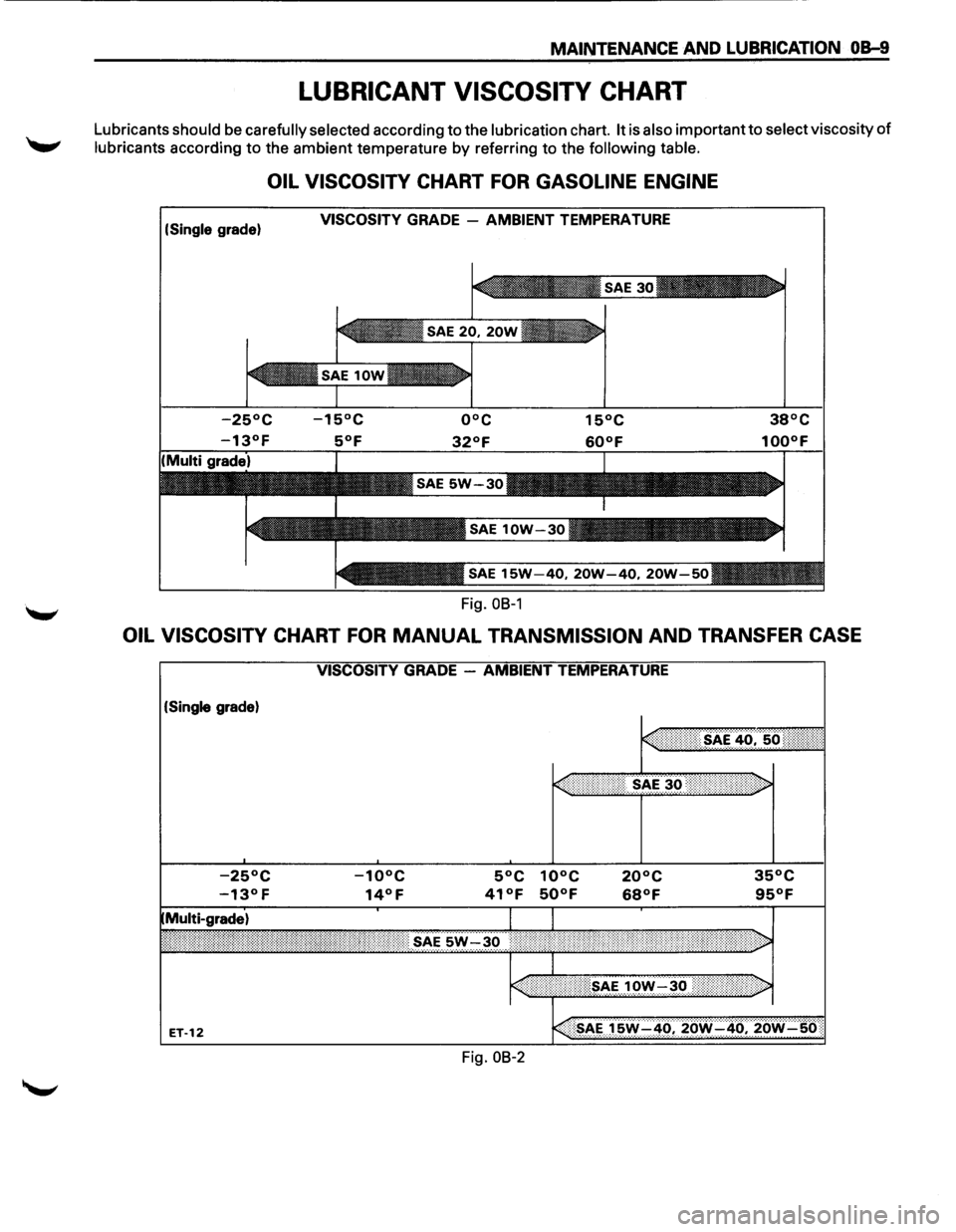
LUBRICANT VISCOSITY CHART
Lubricants should be carefully selected according to the lubrication chart. It is also important to select viscosity of
lubricants according to the ambient temperature by referring to the following table.
OIL VISCOSITY CHART FOR GASOLINE ENGINE
(Single grade) VISCOSITY GRADE -AMBIENT TEMPERATURE
Fig.
OB-1
OIL VISCOSITY CHART FOR MANUAL TRANSMISSION AND TRANSFER CASE
(Single grade)
Fig.
08-2
Page 27 of 1928
,
MAINTENANCE AND LUBRICATION OB-11
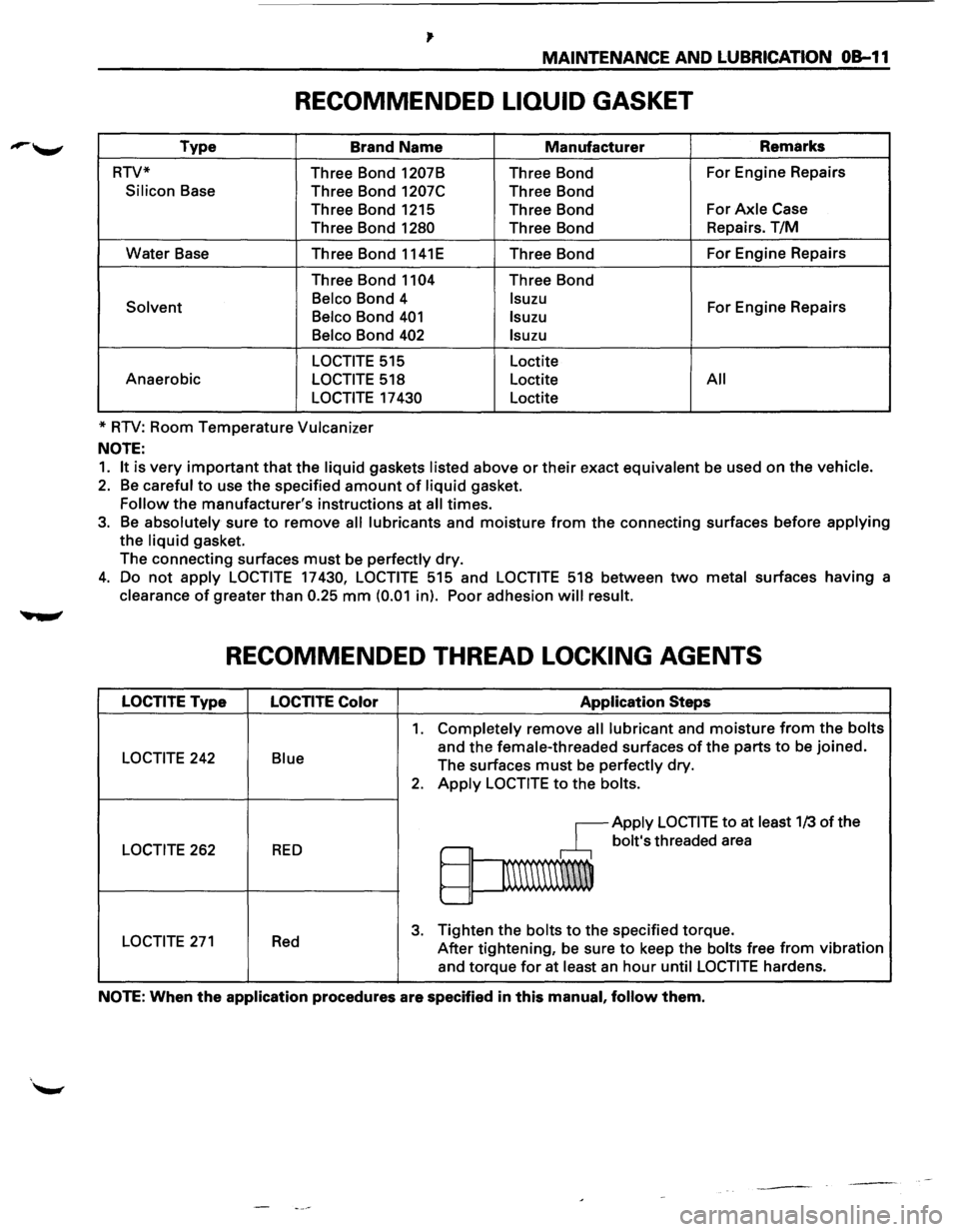
RECOMMENDED LIQUID GASKET
Type Brand Name Manufacturer Remarks
RTV* Three Bond
1207B Three Bond For
Engine Repairs
Silicon Base
Three Bond 1207C Three Bond
Three Bond 1215 Three Bond For
Axle Case
Three Bond
1280 Three Bond Repairs.
T/M
Water Base
Three Bond 1141E Three Bond For
Engine Repairs
Three Bond
1104 Three Bond
Solvent Belco Bond
4 lsuzu For Engine Repairs Belco Bond 401 lsuzu
Belco
Bond 402 lsuzu
LOCTITE
515 Loctite
Anaerobic
LOCTITE 518 Loctite All
LOCTITE
17 430 Loctite
*
RTV: Room Temperature Vulcanizer
NOTE:
1. It is very important that the liquid gaskets listed above or their exact equivalent be used on the vehicle.
2. Be careful to use the specified amount of liquid gasket.
Follow the manufacturer's instructions at all times.
3. Be absolutely sure to remove all lubricants and moisture from the connecting surfaces before applying
the liquid gasket.
The connecting surfaces
must be perfectly dry.
4. Do not apply LOCTITE 17430, LOCTITE 515 and LOCTITE 518 between two metal surfaces having a
clearance
of greater than 0.25 mm (0.01 in). Poor adhesion will result.
RECOMMENDED THREAD LOCKING AGENTS
LOCTITE Type LOCTITE Color Application Steps
1. Completely remove all lubricant and moisture from the bolts
LOCTITE 242 Blue and the female-threaded surfaces of the parts to be joined.
The surfaces
must be perfectly dry.
2. Apply LOCTITE to the bolts.
~Apply LOCTITE to at least 1/3 of the
LOCTITE 262 RED ,.-bolt's threaded area
~
1\\\\\\\W
'--
LOCTITE 271 Red 3. Tighten the bolts to the specified torque.
After tightening, be sure
to keep the bolts free from vibration
and torque
for at least an hour until LOCTITE hardens.
NOTE: When the application procedures are specified in this manual, follow them.
Page 28 of 1928
OB-12 MAINTENANCE AND LUBRICATION
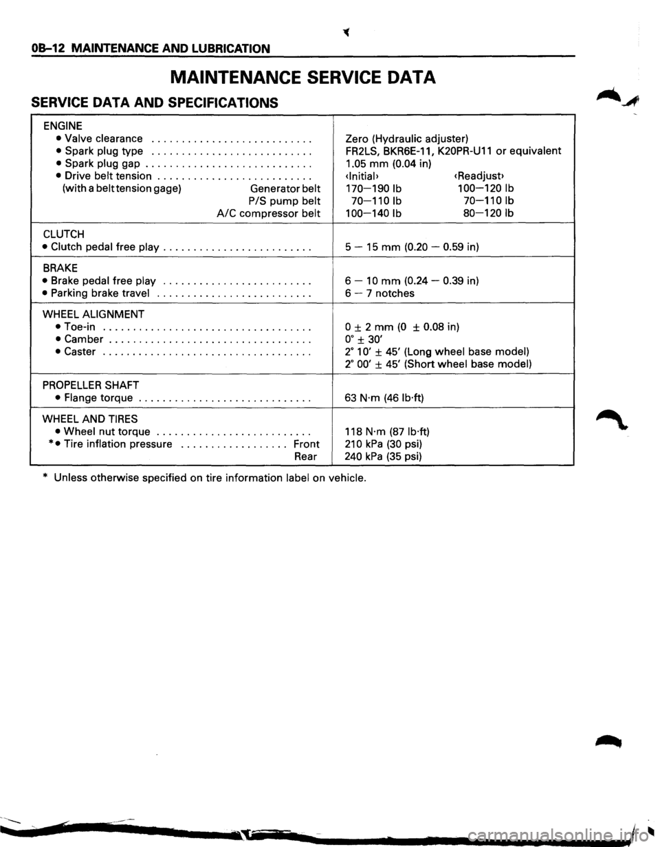
MAINTENANCE SERVICE DATA
SERVICE DATA AND SPECIFICATIONS
ENGINE
• Valve clearance I o o I I I 0 0 0 I 0 o o o o o I 0 o o o 0 0 o o o o Zero (Hydraulic adjuster)
• Spark plug type I I o 0 I o 0 I I I 0 o o o I 0 I o o 0 0 0 o o 0 0 0 FR2LS, BKR6E-1 1, K20PR-U11 or equivalent
•
Spark plug gap ............................ 1.05 mm (0.04 in)
• Drive belt tension ..........................
(with a belttension gage)
Generator belt 170-190 lb 100-120 lb
PIS
pump belt 70-110 lb 70-110 lb
A/C compressor belt 100-140 lb 80-120 lb
CLUTCH
• Clutch pedal free play ......................... 5 -15 mm (0.20 -0.59 in)
BRAKE
• Brake pedal free play o o o o o o o o 0 0 o o o o o 0 0 o o 0 I o o o o 6 -10 mm (0.24 -0.39 in)
• Parking brake travel ••••••••••••••••••\
•• 0 ••••• 6-7 notches
WHEEL
ALIGNMENT
•
Toe-in 0 0 o o 0 0 I 0 0 o o o o 0 0 0 0 o o o o I 0 0 o o 0 0 o o o o 0 I 0 0 ± 2 mm (0 ± 0.08 in)
• Camber .................................. oo ± 30'
•
Caster o o o 0 0 0 0 o o o o o o I 0 0 o o o o 0 0 o o o o 0 o o o o o 0 0 o 2° 1 0' ± 45' (Long wheel base model)
2° 00' ± 45' (Short wheel base model)
PROPELLER SHAFT
• Flange torque ••••••••••••••••••\
•• 0' ••• 0 ••• 63 N·m (46 lb·ft)
WHEEL AND TIRES
• Wheel nut torque o o o o 0 0 o o o o o o o o o o o I o o o o 0 0 0 o 118 N·m (87 lb·ft)
* • Tire inflation pressure •••••••••••••• 0 ••• Front 21 0 kPa (30 psi)
Rear
240 kPa (35 psi)
* Unless otherwise specified on tire information label on vehicle.
~~-.... ¢ .............. .-I ~ -.,~iii~-..--. ....... 2 ........ -. .................. ~~ - I
Page 32 of 1928
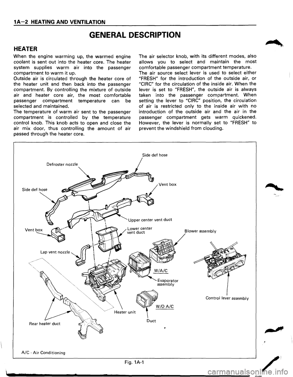
1A-2 HEATING AND VENTILATION
GENERAL DESCRIPTION
HEATER
When the engine warming up, the warmed engine
coolant is sent out into the heater core. The heater
system
supplies warm air into the passenger
compartment to warm it up.
Outside air is
circulated through the heater core of
the heater unit and then back into the passenger
compartment. By
controlling the mixture of outside
air and heater core air, the
most comfortable
passenger compartment temperature can be
selected and maintained.
The temperature
of warm air sent to the passenger
compartment is controlled by the temperature
control knob. This knob acts to open and close the
air
mix door, thus controlling the amount of air
passed through the heater core.
Defroster nozzle
Side
def hose
The air selector knob, with its different modes, also
allows
you to select and maintain the most
comfortable passenger compartment temperature.
The air source
select lever is used to select either
"FRESH" for the introduction of the outside air, or
"CIRC" for the circulation of the inside air. When the
lever is set to "FRESH", the outside air is always
taken into the passenger compartment. When
setting the
lever to "CIRC" position, the circulation
of air is restricted only to the inside air with no
introduction
of the outside air and the air in the
passenger
compartment gets warm quickened.
However, the
lever is normally set to "FRESH" to
prevent the windshield from clouding.
Upper center vent duct
A/C-Air Conditioning Lower
center vent duct
<
Heater unit
Duct
Fig. 1A-1
Blower
assembly
Evaporator assembly
Control lever assembly
W/0 A/C
/'
Page 36 of 1928
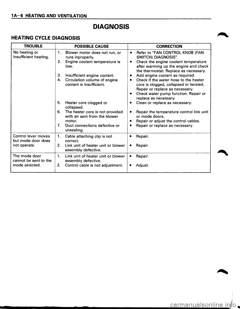
1A-6 HEATING AND VENTILATION
DIAGNOSIS
HEATING CYCLE DIAGNOSIS
TROUBLE POSSIBLE CAUSE CORRECTION
No heating or 1. Blower motor does not run, or • Refer to "FAN CONTROL KNOB (FAN
Insufficient heating.
runs inproperly. SWITCH) DIAGNOSIS".
2. Engine coolant temperature is • Check the engine coolant temperature
low. after warming up the engine and check
the thermostat.
Replace as necessary.
3. Insufficient engine coolant. • Add engine coolant as required .
4. Circulation volume of engine • Check if the water hose to the heater
coolant is insufficient. core is clogged, collapsed or twisted.
Repair
or replace as necessary.
• Check water pump function. Repair or
replace as necessary.
5. Heater core clogged or • Clean or replace as necessary.
collapsed.
6. The heater core is not provided • Repair the temperature control link unit
with air sent from the blower or mode doors.
motor.
• Repair or adjust the control cables.
7. Duct connections defective or • Repair or replace as necessary.
unsealing.
Control lever
moves 1. Cable attaching clip is not • Repair.
but
mode door does correct.
not operate. 2. Link unit of heater unit or blower • Repair.
assembly defective.
The
mode door 1. Link unit of heater unit or blower • Repair.
cannot
be sent to the assembly defective.
mode
selected. 2. Control cable is not adjustment. • Adjust.
_______ __... ..... ..._ ____________ (
Page 38 of 1928
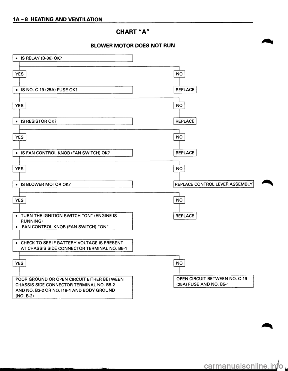
1A-8 HEATING AND VENTILATION
CHART II A"
BLOWER MOTOR DOES NOT RUN
• TURN THE IGNITION SWITCH "ON" (ENGINE IS
RUNNING)
•
FAN CONTROL KNOB (FAN SWITCH) "ON"
• CHECK TO SEE IF BATTERY VOLTAGE IS PRESENT
AT CHASSIS SIDE CONNECTOR TERMINAL NO. B5-1
POOR GROUND OR OPEN CIRCUIT EITHER BETWEEN
CHASSIS SIDE CONNECTOR TERMINAL NO. B5-2
AND NO. B3-2 OR NO. 118-1 AND BODY GROUND
(NO. B-2) (25A)
FUSE AND NO. B5-1
Page 41 of 1928
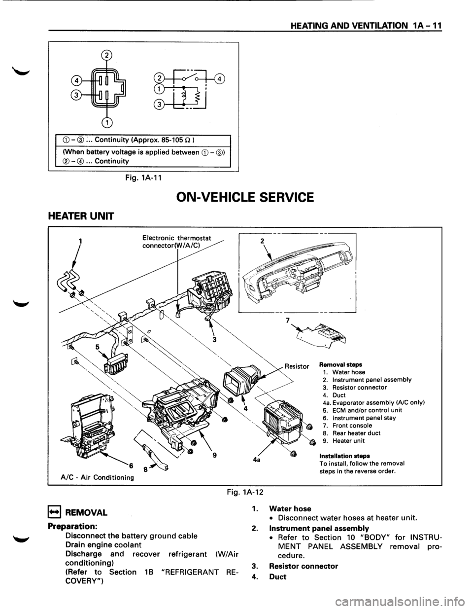
CD-@: .. Continuity (Approx. 85-105 n l
(When battery
voltage is applied between CD-@)
®-@ ... Continuity
Fig. 1A-11
HEATING AND VENTILATION 1A -11
ON-VEHICLE SERVICE
HEATER UNIT
A/C -Air Conditioning
Electronic thermostat
connector(W I A/C)
Removal steps 1. Water hose 2. Instrument panel assembly
3. Resistor connector
4. Duct 4a. Evaporator assembly (AJC only)
5. ECM and/or control unit 6. Instrument panel stay 7. Front console 8. Rear heater duct 9. Heater unit
Installation steps
To
install, follow the removal
steps in the reverse order.
Fig. 1A-12
1••1 REMOVAL
Preparation:
Disconnect the battery ground cable
Drain engine coolant
Discharge and recover refrigerant (W/Air
conditioning)
(Refer to Section 1 B "REFRIGERANT RE
COVERY")
1. Water hose
• Disconnect water hoses at heater unit.
2.
Instrument panel assembly
• Refer to Section 10 "BODY" for INSTRU
MENT PANEL ASSEMBLY removal pro
cedure.
3. Resistor
connector
4. Duct
Page 43 of 1928
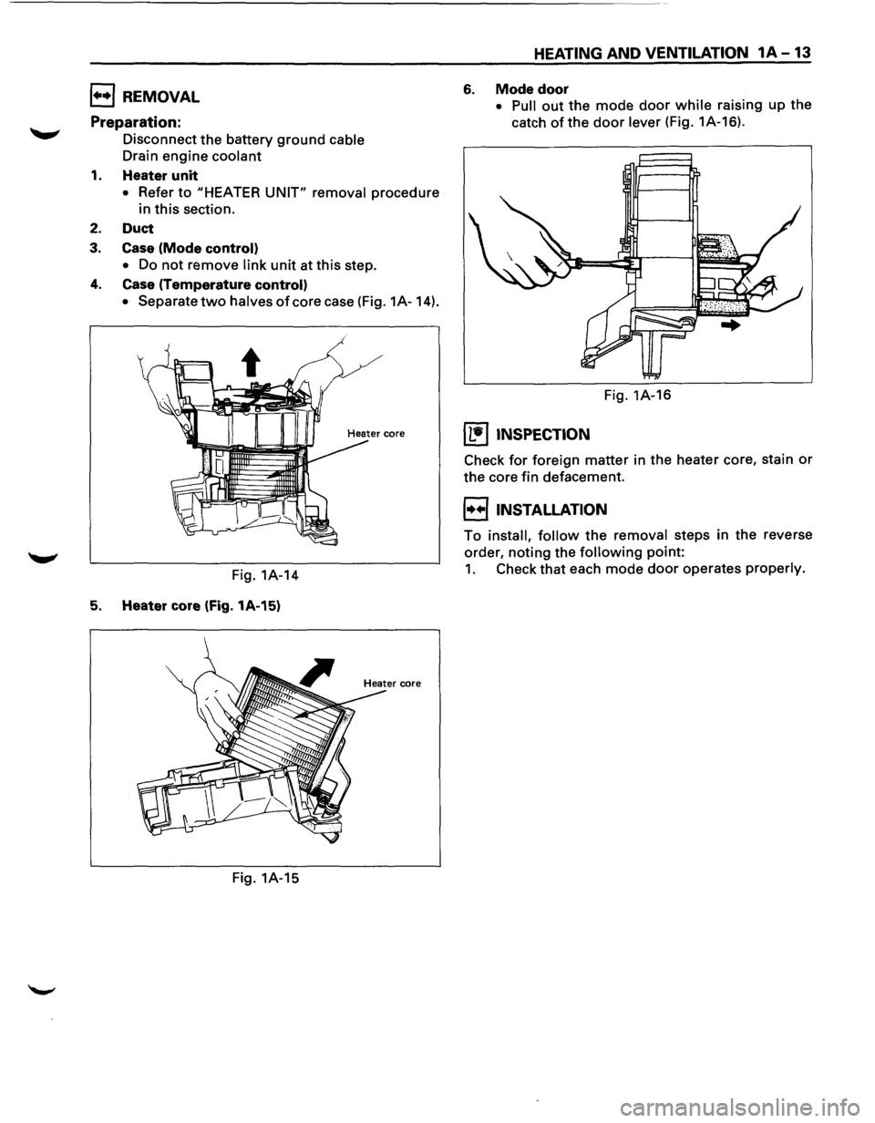
1••1 REMOVAL
Preparation:
Disconnect the battery ground cable
Drain engine coolant
1. Heaterunit
• Refer to "HEATER UNIT" removal procedure
in
this section.
2. Duct
3. Case (Mode control)
• Do not remove link unit at this step.
4. Case (Temperature control)
• Separate two halves of core case (Fig. 1A-14).
Fig. 1A-14
5. Heater core (Fig. 1A-15)
Fig. 1A-15
HEATING AND VENTILATION 1A-13
6. Mode door
• Pull out the mode door while raising up the
catch
of the door lever (Fig. 1A-16).
Fig. 1A-16
(b!] INSPECTION
Check for foreign matter in the heater core, stain or
the core fin defacement.
l••liNSTALLATION
To install, follow the removal steps in the reverse
order,
noting the following point:
1. Check that each mode door operates properly.
Page 44 of 1928
1A-14 HEATING AND VENTILATION
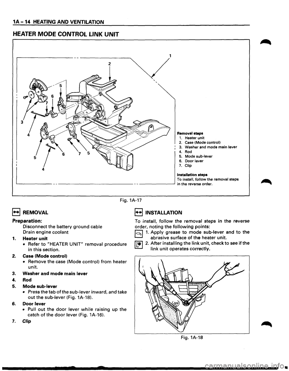
HEATER MODE CONTROL LINK UNIT
2 1
Removal
steps 1. Heater unit 2. Case (Mode control)
3. Washer and mode main lever
4. Rod 5. Mode sub-lever 6. Door lever 7. Clip
Installation
steps
To install, follow the removal steps --------' in the reverse order.
Fig. 1A-17
1••1 REMOVAL
Preparation:
Disconnect the battery ground cable
Drain engine coolant
1. Heater unit
• Refer to "HEATER UNIT" removal procedure
in
this section.
2. Case (Mode control)
•
Remove the case (Mode control) from heater
unit.
3. Washer and mode main lever
4. Rod
5. Mode sub-lever
•
Press the tab of the sub-lever inward, and take
out the sub-lever (Fig. 1A-18).
6. Door lever
• Pull
out the door lever while raising up the
catch
of the door lever (Fig. 1A-16).
7. Clip
I••! INSTALLATION
To install, follow the removal steps in the reverse
order, noting the following points:
1~1 1. Apply grease to mode sub-lever and to the
abrasive surface
of the heater unit.
IL•I 2. After installing the link unit, check to see ifthe
link unit operates correctly.
Fig. 1A-18
•