engine ISUZU TROOPER 1995 Owner's Manual
[x] Cancel search | Manufacturer: ISUZU, Model Year: 1995, Model line: TROOPER, Model: ISUZU TROOPER 1995Pages: 1928
Page 45 of 1928
HEATING AND VENTILATION 1A-15
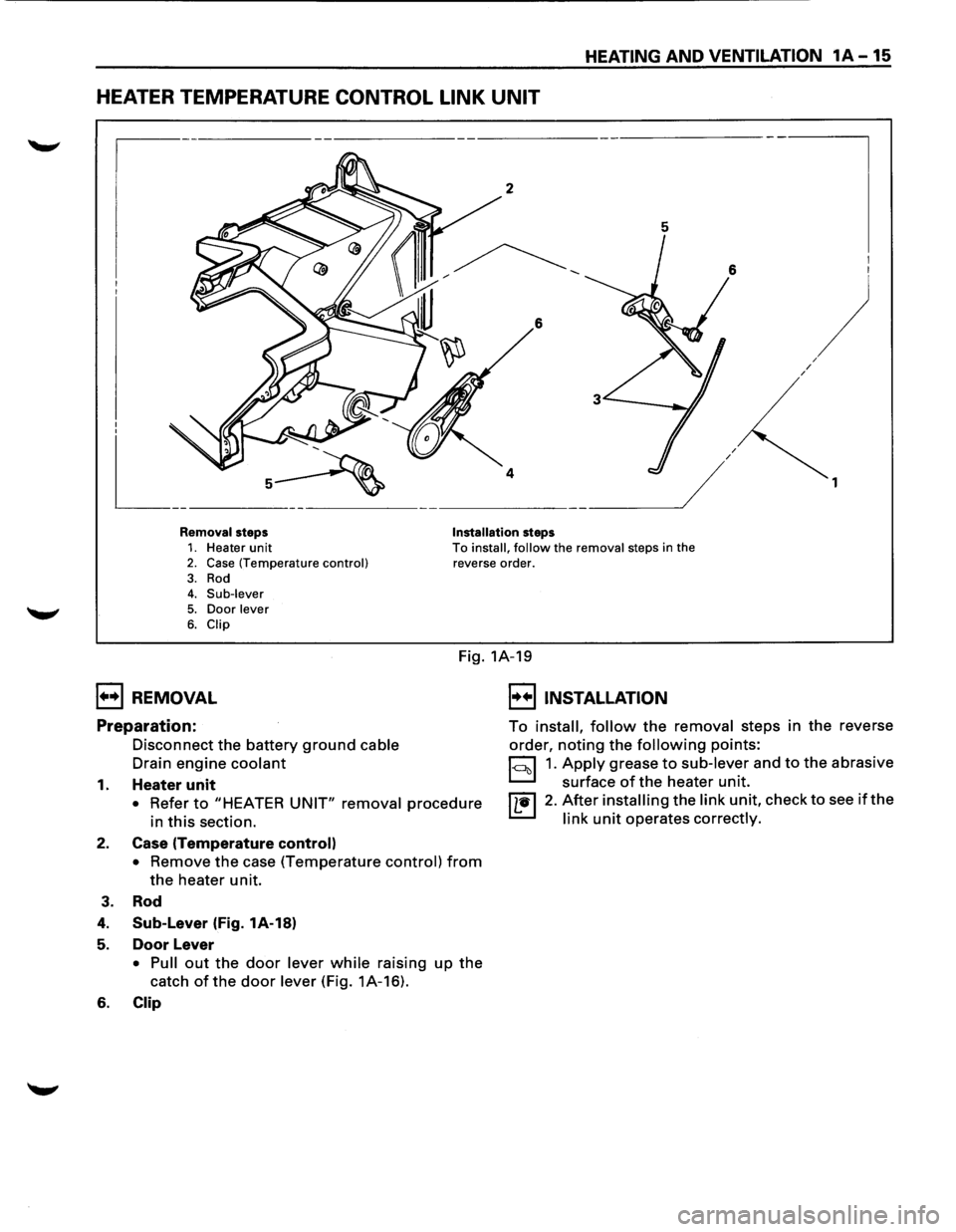
HEATER TEMPERATURE CONTROL LINK UNIT
5
6
/ /
I I
)
1
Removal steps Installation steps 1. Heater unit 2. Case (Temperature control) To install, follow the removal steps in the
reverse order.
3. Rod 4. Sub-lever
5. Door lever 6. Clip
Fig. 1A-19
1••1 REMOVAL
Preparation:
Disconnect the battery ground cable
Drain engine coolant
1. Heater unit
• Refer to "HEATER UNIT" removal procedure
in this section.
2. Case (Temperature control)
• Remove the case (Temperature control) from
the heater unit.
3. Rod
4. Sub-Lever (Fig. 1A-18)
5. Door Lever
• Pull out the door lever while raising up the
catch of the door lever (Fig. 1A-16).
6. Clip
I••! INSTALLATION
To install, follow the removal steps in the reverse
order,
noting the following points:
1~1 1. Apply grease to sub-lever and to the abrasive
surface
of the heater unit.
I L•l 2. After installing the link unit, check to see if the
link unit operates correctly.
Page 57 of 1928
The refrigeration cycle includes the following four
processes as the refrigerant changes repeatedly
from liquid to gas and back to liquid while circulat
ing.
EVAPORATION
The refrigerant is changed from a liquid to a gas in
side
the evaporator. The refrigerant mist that enters
the evaporator vaporizes readily. The liquid refrige
rant removes
the required quantity of heat (latent
heat of vaporization) from the air around the evap
orator core cooling fins and rapidly vaporizes.
Removing the heat cools the air, which is then
radiated
from the fins and lowers the temperature of
the air inside the vehicle.
The refrigerant liquid sent from the expansion valve
and the vaporized refrigerant gas are both present
inside the
evaporator and the liquid is converted to
gas.
With this change from liquid to gas, the pressure
inside
the evaporator must be kept low enough for
vaporization to occur at a lower temperature.
Because of that, the vaporized refrigerant is sucked
into the compressor.
COMPRESSION
The refrigerant is compressed by the compressor
until it is easily liquefied at normal temperature.
The vaporized
refrigerant in the evaporator is sucked
into the compressor. This action maintains the
refrigerant inside the evaporator at a low pressure
so
that it can easily vaporize, even at low tempera
tures close to ooc (32°F).
Also, the refrigerant sucked into the compressor is
compressed inside the
cylinder to increase the
pressure and temperature to values such that the
refrigerant can easily liquefy at normal ambient
temperatures.
CONDENSATION
The refrigerant inside the condenser is cooled by the
outside air and changes from gas to liquid.
The high temperature, high pressure gas coming
from the compressor is cooled and liquefied by the
condenser with outside air and accumulated in the
receiver/drier. The heat radiated to the outside air by
the high temperature, high pressure gas in the
compressor is called heat of condensation. This is
the total quantity of heat (heat of vaporization) the
refrigerant removes
from the vehicle interior via the
evaporator and the work (calculated as the quantity
of heat) performed for compression.
'-' EXPANSION
The expansion valve lowers the pressure of the
refrigerant liquid so that it can easily vaporize.
AIR CONDITIONING 1 B -3
The process of lowering the pressure to encourage
vaporization before the
liquefied refrigerant is sent
to the evaporator is called expansion. In addition,
the expansion valve controls the flow rate of the
refrigerant liquid while decreasing the pressure.
That is, the quantity of refrigerant liquid vaporized
inside
the evaporator is determined by the quantity
of heat which must be removed at a prescribed
vaporization temperature.
It is important that the
quantity of refrigerant be controlled to exactly the
right value.
COMPRESSOR
It compressor performs two main functions:
It compresses low-pressure and low-temperature
refrigerant vapor from the evaporator into high
pressure and high-temperature
refrigerant vapor to
the condenser. And it pumps refrigerant and
refrigerant
oil through the air conditioning system.
This vehicle is equipped with five-vane rotary com
pressor.
The
thermo sensor is installed to the front head of
the compressor to protect it by stopping its
operation when the refrigerant gas is insufficient or
when the temperature is abnormally high.
• OFF ...... 160 ±soc (320.0 ± 9.0°F)
• ON
...... 135 ±soc (27S.O ± 9.0°F)
The specified amount of the compressor oil is 1SOcc
(S.O fl.oz.).
The oil used in the HFC-134a system compressor
differs from that used in R-12 systems.
Also, compressor oil to be used varies according to
the compressor model. Be sure to avoid mixing two
or more different types of oil.
If the wrong oil is used, lubrication will be poor and
the compressor will seize or malfunction.
The magnetic clutch connector is a waterproof
type.
MAGNETIC CLUTCH
The compressor is driven by the drive belt from the
crank
pulley of the engine. If the compressor is ac
tivated each
time the engine is started, this causes
too much load to the engine. The magnetic clutch
transmits the power from the engine to the com
pressor and activates it when the air conditioning is
"ON". Also, it cuts off the power from the engine to
the compressor when the air conditioning is "OFF".
(Magnetic clutch repair procedure can be found in
Section 1 D.)
Page 64 of 1928
18-10 AIR CONDITIONING
CHECKING REFRIGERANT SYSTEM
WITH MANIFOLD
GAUGE
Since Refrigerant-134a (HFC-134a) is used in the air
conditioning system in this vehicle, be sure to use
manifold gauges, charging hoses and other air
conditioning service tools for HFC-134a when
checking the refrigerant system.
Conditions;
• Run the engine at Idling
• Air conditioning switch is "ON"
• Run the blower motor at "HIGH" position
• Temperature control lever set to "MAX COLD"
•
Air source selector lever at "CIRC"
• Open
the engine hood
• Close all the doors
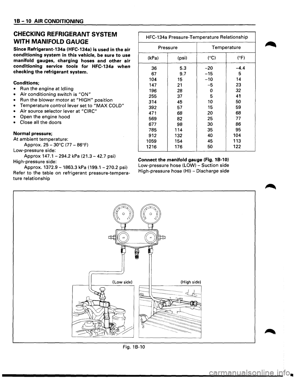
Normal pressure;
At ambient temperature:
Approx. 25 -30°C (77 -86°F)
Low-pressure side:
Approx 147.1-294.2 kPa (21.3-42.7 psi)
High-pressure side:
Approx. 1372.9-1863.3 kPa (199.1 -270.2 psi}
Refer
to the table on refrigerant pressure-tempera
ture relationship
(Low side)
HFC-134a Pressure-Temperature Relationship
Pressure
Temperature
(kPa) (psi) (oC)
36 5.3 -20
67 9.7 -15
104
15 -10
147 21 -5
196 28 0
255 37 5
314
45 10
392
57 15
471 68 20
569
82 25
677 98 30
785 114 35
912 132
40
1059 154 45
1216
176 50
Connect the manifold gauge (Fig. 18-10)
Low-pressure hose (LOW) -Suction side
High-pressure hose
(HI)-Discharge side
(High side)
(oF)
-4.4
5
14
23
32
41
50
59
68
77
86
95
104
113
122
Fig. 18-10
•
Page 68 of 1928
18-14 AIR CONDITIONING
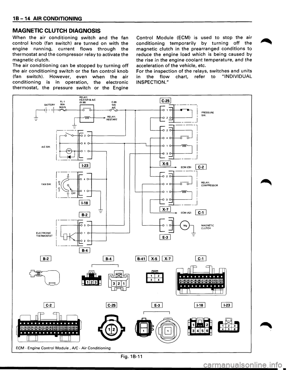
MAGNETIC CLUTCH DIAGNOSIS
When the air conditioning switch and the fan
control knob (fan switch) are turned on with the
engine running, current flows through the
thermostat and the compressor relay to activate the
magnetic clutch.
The air conditioning can be stopped by turning off
the air conditioning switch or the fan control knob
(fan switch). However, even when the air
conditioning is in operation, the electronic
thermostat, the pressure switch or the Engine
BATTER y
~
A/C SW.
FAN SW.
FL-1 BOA MAIN -.Y""'
I
RELAY; HEATER&A/C (8-36)
-
·~
~-----;::: -
I ,--<> -v--ro 2
I 6
! -&r ro 1 l ~ .... --~-'---
11-231
r-g-I 4
I~ 0 I 2 1
l __ 9_ OFF -
lli!J
~
r-----3 I
I 1
I 2 -
ELECTRONIC ~ THERMOSTAT
l __ _
C-20 10A Jd.C
RELAY; RESTART
-=-
ECM -Engine Control Module , NC -Air Conditioning
Control Module (ECM) is used to stop the air
conditioning temporarily by turning off the
magnetic clutch in the prearranged conditions to
reduce the engine load which is being caused by
the rise in the engine coolant temperature, and the
acceleration of the vehicle, etc.
For
the inspection of the relays, switches and units
in the flow chart, refer to "INDIVIDUAL
INSPECTION."
,....-1
2 ......_
.....-=.-2
40. r-
1v-
3
......._ =--
~
I ___ j
PRESSURE
SW.
ECMIC91
~
---2 ----l
•o--
1v-
3
-~-@]
~1
L
[ill
I
I RELAY; COMPRESSOR
I
I I ___ j
ECMIA21 ~
:=:>
MAGNETIC
CLUTCH
,.----I In_ r-r
A1 Kl ., .. ...... A& .. A7 AI ld A10 A11A12 .... •• ., .. a1o an 112
'It!
~
~
Fig.1B-11
Page 69 of 1928
AIR CONDITIONING 1 B -15
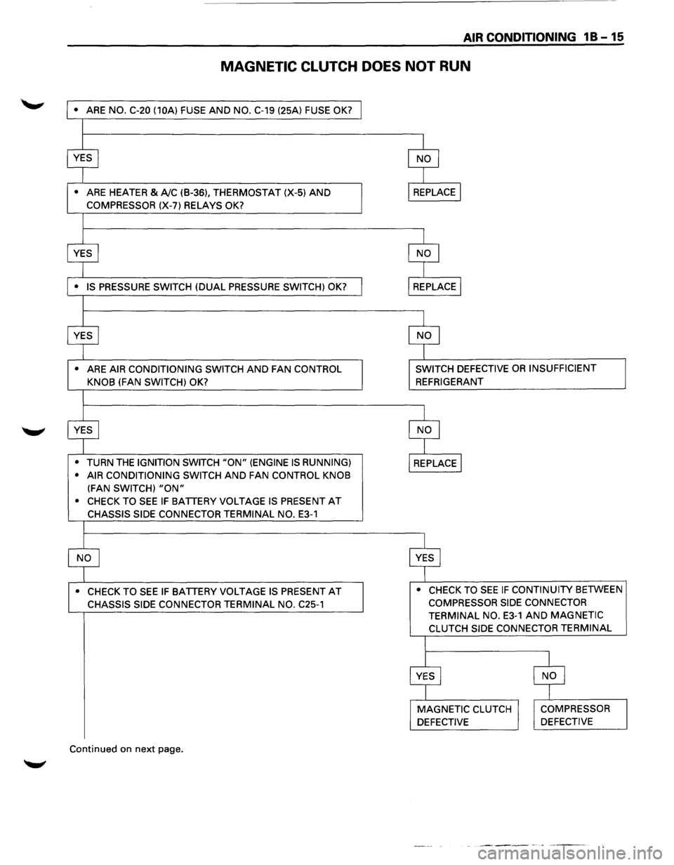
MAGNETIC CLUTCH DOES NOT RUN
• ARE NO. C-20 (10A) FUSE AND NO. C-19 (25A) FUSE OK?
•
ARE HEATER & A!C (B-36), THERMOSTAT (X-5) AND
COMPRESSOR (X-7) RELAYS OK?
•
ARE AIR CONDITIONING SWITCH AND FAN CONTROL
KNOB
(FAN SWITCH) OK?
•
TURN THE IGNITION SWITCH "ON" (ENGINE IS RUNNING)
• AIR CONDITIONING SWITCH
AND FAN CONTROL KNOB
(FAN SWITCH) "ON"
• CHECK TO SEE IF BATTERY VOLTAGE IS PRESENT AT
CHASSIS SIDE CONNECTOR TERMINAL NO. E3-1
• CHECK TO SEE IF BATTERY VOLTAGE IS PRESENT AT
CHASSIS SIDE CONNECTOR TERMINAL NO. C25-1
Continued on next page.
SWITCH DEFECTIVE OR INSUFFICIENT
REFRIGERANT
• CHECK TO
SEE IF CONTINUITY BETWEEN
COMPRESSOR SIDE CONNECTOR
TERMINAL NO.
E3-1 AND MAGNETIC
CLUTCH SIDE CONNECTOR TERMINAL
Page 73 of 1928
AIR CONDITIONING 1 B -19
ON-VEHICLE SERVICE
GENERAL REPAIR PROCEDURE
Precautions for Replacement or Repair of Air
Conditioning Parts
There are certain procedures, practices and pre
cautions
that should be followed when servicing air
conditioning systems:
• Keep your work area clean.
•
Always wear safety goggle and protective gloves
when working on refrigerant systems.
• Beware of the danger of carbon monoxide fumes
caused by running the engine.
• Beware of discharged refrigerant in enclosed or
improperly ventilated garages.
• Always disconnect the negative battery cable and
discharge and recover the refrigerant
whenever
repairing the air conditioning system.
• When discharging and recovering the refrigerant,
do not allow refrigerant to discharge too fast; it
will draw compressor oil out of the system.
• Keep moisture and contaminants out of the sys
tem.
When disconnecting or removing any lines
or parts, use plugs or caps to close the fittings
immediately.
Never remove the caps or plugs until the lines or
parts are reconnected or installed.
•
When disconnecting or reconnecting the lines,
use
two wrenches to support the line fitting, to
prevent from twisting or other damage.
• Always install new 0-rings whenever a connec
tion is disassembled.
• Before connecting any hoses or lines, apply new
specified compressor oil to the 0-rings.
• When removing and replacing any parts which
require discharging the refrigerant circuit, the
operations described in
this section must be per
formed in the following sequence:
1. Use the J-39500 (ACR4
: HFC-134a Refrigerant
Recovery/Recycling/Recharging/System)
or
equivalent to thoroughly discharge and re
cover
the refrigerant.
2. Remove and replace the defective part.
3.
After evacuation, charge the air conditioning
system and check for leaks.
Repair of Refrigerant Leaks
Refrigerant Line Connections
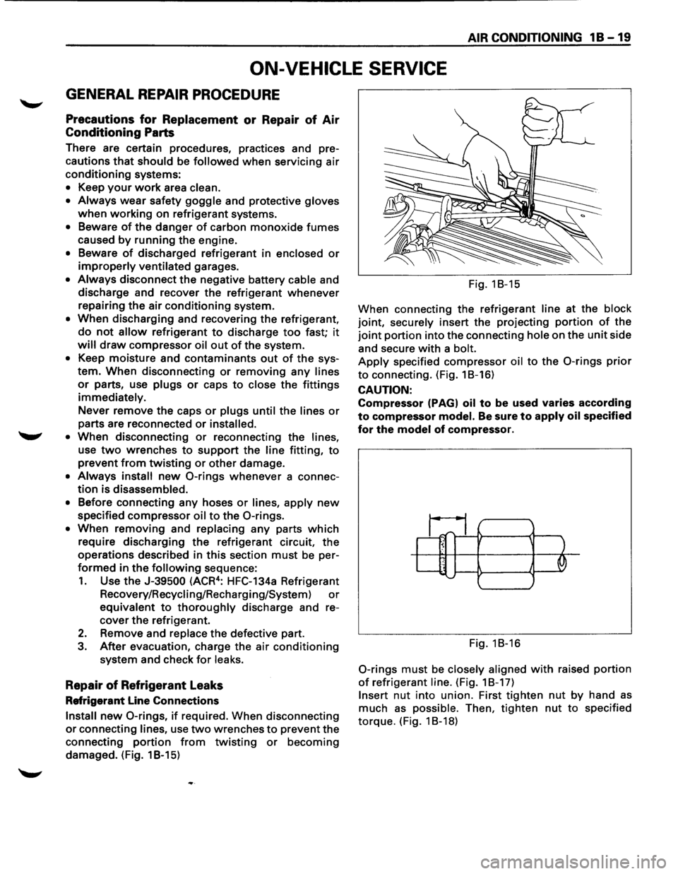
Install new 0-rings, if required. When disconnecting
or connecting lines, use two wrenches to prevent the
connecting
portion from twisting or becoming
damaged. (Fig. 1 B-15) Fig.
18-15
When connecting the refrigerant
line at the block
joint, securely insert the projecting portion of the
joint portion into the connecting hole on the unit side
and secure
with a bolt.
Apply specified compressor oil to the 0-rings prior
to connecting. (Fig. 18-16)
CAUTION:
Compressor (PAGI oil to be used varies according
to compressor model. Be sure to apply oil specified
for the model of compressor.
~1;1_ ~ ' .. J '--......
Fig. 18-16
0-rings must be closely aligned with raised portion
of refrigerant line. (Fig. 18-17)
Insert nut into union. First tighten nut by hand as
much as possible. Then, tighten nut to specified
torque. (Fig. 1 8-18)
Page 77 of 1928
6.
7.
Perform system leak test.
• Charge the system with approx. 200 g (0.44
lbs) of HFC-134a.
• Make sure the high pressure valve of the
manifold gauge is closed.
• Check
to ensure that the degree of pressure
does
not change.
• Check for refrigerant leaks by using a HFC-
134a leak detector.
• If a leak occurs, recover the refrigerant. Repair
the leak, and start all over again from the first
step of evacuation.
If no leaks are found, continue charging re
frigerant to the air conditioning system.
• Charge the refrigerant until the scale reading
decreases
by the amount of the charge
specified.
Specified
amount g (lbs.) I 750 (1.65)
• If charging the system becomes difficult:
( 1) Run the engine at idle and close all the
vehicle doors.
(2) Turn A!C switch "ON".
(3) Set the fan switch to its highest position.
(4) Set air source selector lever to "CIRC".
(5) Slowly open the low side valve on the
manifold gauge set.
WARNING: BE ABSOLUTELY SURE NOT TO
OPEN THE HIGH PRESSURE VALVE OF THE
MANIFOLD GAUGE. SHOULD THE HIGH
PRESSURE VALVE BE OPENED, THE HIGH
PRESSURE REFRIGERANT WOULD FLOW
BACKWARD, AND
THIS MAY CAUSE THE
REFRIGERANT CONTAINER TO BURST.
8. When finished with the refrigerant charging,
close the low pressure valve of the manifold
gauge and container valve.
9. Check for refrigerant leaks.
AIR CONDITIONING 18 -23
Checking
the A/C system
1. Run the engine and close all the vehicle doors.
2. Turn A!C switch "ON", set the fan switch to its
highest position, set air source
lever to "CIRD"
and set temperature lever to full cool position.
3. Check the high and low pressure of the manifold
gauge.
• Immediately after charging refrigerant, both
high and low pressure are slightly high, but
they settle down to the pressure guidelines
shown below:
Ambient temperature: 25-30°C (77 -86°F)
Pressure guidelines:
• High-pressure side;
Approx. 1372.9-1863.3kPa (199.1-270.2psi)
• Low-pressure side;
Approx. 147.1-294.2 kPa (21.3-42.7 psi)
• If an abnormal pressure is found, refer to
"CHECKING REFRIGERANT SYSTEM WITH
MANIFOLD
GAUGE" in this section.
4. Put your hand in front of the air outlet and move
the temperature control lever of the control
panel
to different positions. Check if the outlet
temperature changes as selected by the control
knob.
Page 80 of 1928
1 B -26 AIR CONDITIONING
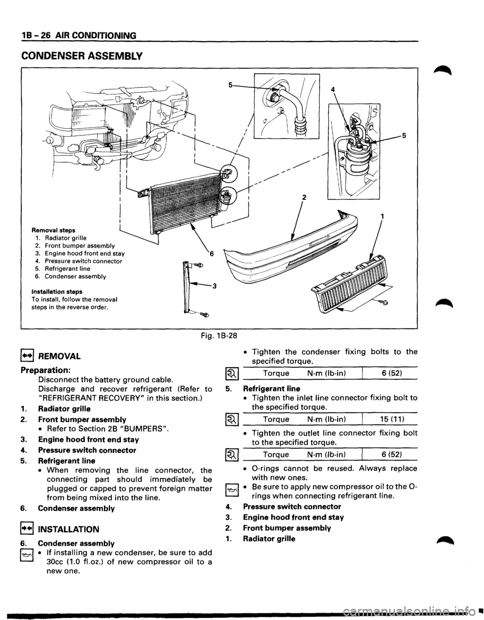
CONDENSER ASSEMBLY
Removal steps 1. Radiator grille
2. Front bumper assembly 3. Engine hood front end stay
4. Pressure switch connector 5. Refrigerant line
6. Condenser assembly
Installation steps To install, follow the removal
steps in the reverse order.
4
5
Fig. 1 B-28
1••1 REMOVAL
Preparation:
Disconnect the battery ground cable.
Discharge and recover refrigerant (Refer to
"REFRIGERANT RECOVERY" in this section.)
1. Radiator grille
2. Front bumper assembly
•
Refer to Section 2B "BUMPERS".
3. Engine hood front end stay
4. Pressure switch connector
5. Refrigerant line
• When removing the line connector, the
connecting part should immediately be
plugged or capped to prevent foreign matter
from being mixed into the line.
6. Condenser assembly
!••I INSTALLATION
6. Condenser assembly
l'l::r.l • If installing a new condenser, be sure to add
30cc ( 1.0
fl. oz.) of new compressor oil to a
new one.
• Tighten the condenser fixing bolts to the
specified
torque.
~~~ Torque N·m (lb-in) 6 (52)
5. Refrigerant line
•
Tighten the inlet line connector fixing bolt to
the specified torque.
~~~ Torque N·m (lb-in) 15 (11)
• Tighten the outlet line connector fixing bolt
to the specified torque.
~~~ Torque N-m (lb-in) 6 (52)
• 0-rings cannot be reused. Always replace
with new ones.
l'l::r.l • Be sure to apply new compressor oil to the 0-
rings when connecting refrigerant line.
4. Pressure switch connector
3. Engine hood front end stay
2. Front bumper assembly
1. Radiator grille
•
Page 92 of 1928
1 D-4 COMPRESSOR OVERHAUL
6. Perform oil return operation.
7. Remove the compressor and recheck the
amount of oil.
8. Adjust the compressor oil, if necessary.
Collected Amount
more than 90cc
(3.0
fl.oz.)
Charging Amount
same as collected amount
less than 90cc (3.0 fl.oz.) 90cc (3.0 fl.oz.)
Checking and Adjusting for Compressor
Replacement
150cc (5.0 fl.oz.) of oil is charged in compressor
(service parts).
So it is necessary to drain the
proper
amount of oil from the new compressor.
1. Perform oil return operation.
2. Discharge and recover refrigerant and remove
the compressor.
3. Drain the compressor oil and measure the
extracted
oil.
4. Check the compressor oil for contamination.
5. Adjust oil level as required.
Amount of oil drained
from used compressor
less than 90cc
(3.0
fl.oz.)
Draining amount of oil
from new compressor
Same as drained
amount
more than 90cc (3.0 fl.oz.) 90cc (3.0 fl.oz.)
6. Evacuate, charge and perform oil return oper
ation.
7. Check system operation.
CONTAMINATION OF COMPRESSOR OIL
Unlike engine oil, no cleaning agent is added to the
compressor
oil. Even if the compressor runs for a
long period
of time (approximately 1 season), the
oil never becomes contaminated as long
as there is
nothing
wrong with the compressor or its method
of use.
Inspect the extracted oil for any of the following
conditions:
• The capacity of the oil has increased.
• The oil has changed color to red.
• Foreign substances, metal powder, etc., are
present in the oil.
If any of these conditions exists, compressor oil
is contaminated. Whenever contaminated com
pressor
oil is discovered, the receiver/dryer must
be
replaced.
OIL RETURN OPERATION
There is close affinity between the oil and the
refrigerant. During normal operation, part
of the oil
recirculates
with the refrigerant in the system.
When checking the
amount of oil in the system, or
replacing any component of the system, the com
pressor
must be run in advance for oil return oper
ation. The procedure is as
follows:
1. Open the all doors and engine hood.
2. Start the engine and air conditioning switch is
"ON" and Set the fan control knob at its hig
hest position.
3. Run the compressor for more than 20 minutes
between
800 and 1,000 rpm in order to operate
the system.
4. Stop the engine.
REPLACEMENT OF COMPONENT PARTS
When replacing system component parts, supply
the following
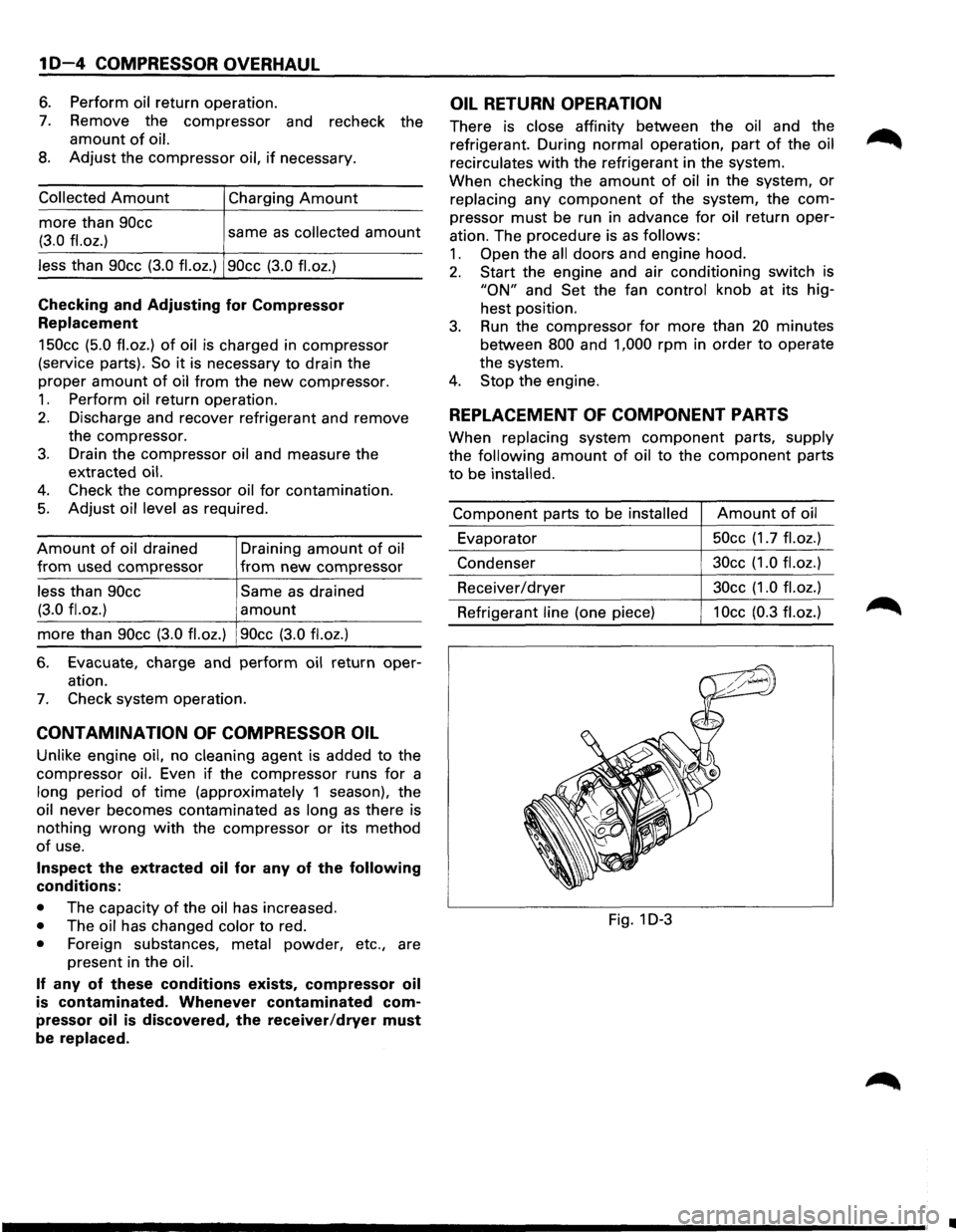
amount of oil to the component parts
to be installed.
Component parts to be installed Amount of oil
Evaporator 50cc
(1.7
fl.oz.)
Condenser 30cc
(1.0 fl.oz.)
Receiver/dryer 30cc
(1.0 fl.oz.)
Refrigerant line (one piece) 1 Occ (0.3 fl. oz.)
Fig. 1 D-3
•
Page 109 of 1928
SHEET METAL 2C-1
SECTION 2C
SHEET METAL
NOTE:
Fasteners are important attaching parts in that they could affect the performance of vital components and
systems,
and/or could result in major repair expense. They must be replaced with one of the same part number or
with an equivalent part if replacement becomes necessary. Do not use a replacement part of lesser quality or
substitute design. Torque values must be used as specified during reassembly to assure proper retention of these
parts. Refer
to Torque Value Chart in the general information of Section "OA".
CONTENTS
General Description . . . . . . . . . . . . . . . . . . . . 2C-1
On-Vehicle Service . . . . . . . . . . . . . . . . . . . . 2C-2
Cowl Cover . . . . . . . . . . . . . . . . . . . . . . . . . 2C-2
Engine Hood . . . . . . . . . . . . . . . . . . . . . . . . 2C-3
Engine Hood Hinge . . . . . . . . . . . . . . . . . . 2C-4
Engine Hood Lock .................... 2C-5
Radiator Grill and Front end
Lower Panel
....................... 2C-6
Front Fender Panel ................... 2C-7
Body Mounting ...................... 2C-9
GENERAL DESCRIPTION
This section includes items of front end sheet metal
that are attached by bolts, screws
or clips and related
accessory components.
Anti-corrosion materials have been applied to the
interior surfaces
of some metal panels to provide rust resistance.
When servicing these panels, areas on
which this material has been disturbed should
be
properly recoated with service-type anti-corrosion
material.