engine ISUZU TROOPER 1995 Repair Manual
[x] Cancel search | Manufacturer: ISUZU, Model Year: 1995, Model line: TROOPER, Model: ISUZU TROOPER 1995Pages: 1928
Page 333 of 1928
HYDRAULIC BRAKES SA-13
BRAKE PEDAL ASSEMBL V
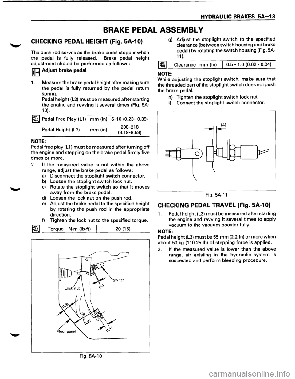
CHECKING PEDAL HEIGHT (Fig. SA-1 0)
The push rod serves as the brake pedal stopper when
the pedal is fully released. Brake pedal height
adjustment
should be performed as follows:
I~FI Adjust brake pedal
1. Measure the brake pedal height after making sure
the pedal is
fully returned by the pedal return
spring. Pedal height
(L2) must be measured after starting
the engine and revving
it several times (Fig. 5A-
10).
1~1 Pedal Free Play (L 1) mm (in) 6-10 (0.23- 0.39)
Pedal Height (L2)
NOTE:
mm (in) 208-218
(8.19-8.58)
Pedal free play (L 1) must be measured after turning off
the engine and stepping on the brake pedal firmly five
times
or more.
2. If the measured value is not within the above
range, adjust the brake
pedal as follows:
a) Disconnect the stoplight switch connector.
b) Loosen the stoplight switch lock nut.
c) Rotate the stoplight switch so that it moves
away
from the brake pedal.
d) Loosen the lock nut on the push rod.
e) Adjust the brake pedal to the specified height
by rotating the push rod in the appropriate
direction.
f) Tighten the lock nut to the specified torque.
~~~ Torque N·m (lb·ft) 20 (15) --------~----~---
Fig. 5A-10
g) Adjust the stoplight switch to the specified
clearance (between switch housing and brake
pedal)
by rotating the switch housing (Fig. 5A-
11 ).
1@1 Clearance mm (in) I 0.5-1.0 (0.02-0.04)
NOTE:
While adjusting the stoplight switch, make sure that
the threaded part of the stoplight switch does not push
the brake
pedal.
h) Tighten the stoplight switch lock nut.
i) Connect the stoplight switch connector.
Fig.
5A-11
CHECKING PEDAL TRAVEL (Fig. SA-1 0)
1. Pedal height (L3) must be measured after starting
the engine and revving
it several times to apply
vacuum
to the vacuum booster fully.
NOTE:
Pedal height (L3) must be 55 mm (2.2 in) or more when
about 50 kg (11 0.25 I b) of stepping force is applied.
2. If the measured value is lower than the above
range, air existing in the hydraulic system is
suspected and perform bleeding procedure.
Page 344 of 1928
SA 1-2 BRAKE BOOSTER SYSTEM
ON-VEHICLE SERVICE
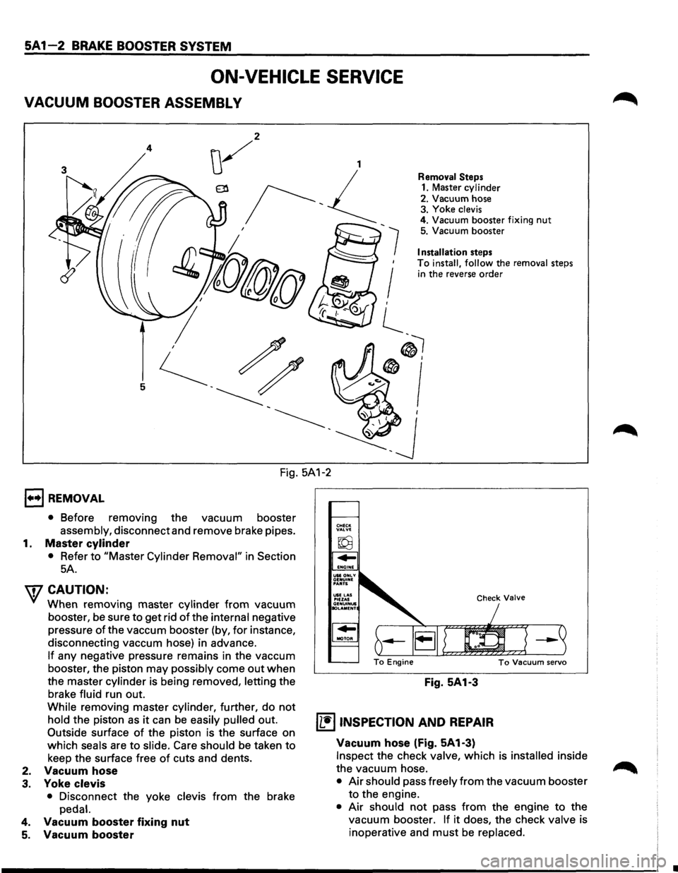
VACUUM BOOSTER ASSEMBLY
4
7
'
I ,
l_
Removal Steps 1. Master cylinder
2. Vacuum hose
3. Yoke clevis 4. Vacuum booster fixing nut 5. Vacuum booster
Installation steps
To install, follow the removal steps in the reverse order
®I
®'
Fig. 5A1-2
1••1 REMOVAL
• Before removing the vacuum booster
assembly, disconnect and remove brake pipes.
1. Master cylinder
• Refer to "Master Cylinder Removal" in Section
5A.
'\fCAUTION:
When removing master cylinder from vacuum
booster, be sure to get rid
of the internal negative
pressure
of the vaccum booster (by, for instance,
disconnecting vaccum hose) in advance.
If any negative pressure remains in the vaccum
booster, the piston may
possibly come out when
the master cylinder is being removed, letting the
brake
fluid run out.
While removing master cylinder, further, do not
hold the piston as it can be easily pulled out.
Outside surface of the piston is the surface on
which
seals are to slide. Care should be taken to
keep the surface free of cuts and dents.
2. Vacuum hose
3. Yoke clevis
• Disconnect the yoke clevis from the brake
pedal.
4. Vacuum booster fixing nut
5. Vacuum booster
Fig. 5A1-3
~ INSPECTION AND REPAIR
Vacuum hose (Fig. 5A1-3)
Inspect the check valve, which is installed inside
the vacuum hose.
• Air should pass freely from the vacuum booster
to the engine.
• Air should not pass from the engine to the
vacuum booster.
If it does, the check valve is
inoperative and
must be replaced.
•
Page 345 of 1928
l·u·IINSTALLATION
5. Vacuum booster
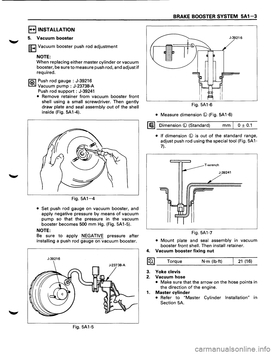
I~EI Vacuum booster push rod adjustment
NOTE:
When replacing either master cylinder or vacuum
booster, be sure
to measure push rod, and adjust if
required.
~ Push rod gauge : J-39216
~ Vacuum pump : J-23738-A
Push rod
support: J-39241
• Remove retainer from vacuum booster front
shell using a small screwdriver. Then gently
draw plate and seal assembly out of the shell
inside (Fig. 5A1-4).
Fig.
5A1-4
• Set push rod gauge on vacuum booster, and
apply negative pressure by means of vacuum
pump so that the pressure in the vacuum
booster becomes
500 mm Hg. (Fig. 5A1-5).
NOTE:
Be sure to apply NEGATIVE pressure after
installing a push rod gauge on vacuum booster.
J-39216
Fig. 5A1-5
BRAKE BOOSTER SYSTEM 5A1-3
Fig. 5A1-6
• Measure dimension (b) (Fig. 5A 1-6)
~~~ Dimension (b) (Standard) mm I 0 ± 0.1
• If dimension (b) is out of the standard range,
adjust push rod using the
special tool (Fig. 5A 1-
7).
T·wrench
J-39241
Fig. 5A1-7
• Mount plate and seal assembly in vacuum
booster
front shell. Then install retainer.
4. Vacuum booster fixing nut
I~I ____ T_o_rq_u_e _______ N_·m __ (l_b·_ft_) __ ~_2_1_(_16_)_
3. Yoke clevis
2. Vacuum hose
• Make sure that the arrow on the hose points in
the direction
of the engine.
1.
Master cylinder
• Refer to "Master Cylinder Installation" in
Section 5A.
Page 369 of 1928
REAR WHEEL ANTILOCK BRAKE SYSTEM 5A3-1
SECTION 5A3
REAR WHEEL ANTILOCK BRAKE SYSTEM
(RWAL}
w CAUTION:
• All brake attaching fasteners are an important attaching part in that they could affect performance of vital
parts and systems, and/or could result in major repair expense. They must be replaced with one of the same
part
number or with an equivalent part if replacement becomes necessary. Do not use replacement parts of
lesser quality or substitute design. Torque values must be used as specified during reassembly to assure
proper retention of these parts.
CONTENTS
Introduction . . . . . . . . . . . . . . . . . . . . . . . . . 5A3· 1
General Description . .
. . . . . . . . . . . . . . .
5A3· 1
Rear
Wheel Antilock (RWAL) Control
Parts Location . .
. . . . . . . . . . . . . . . . .
5A3· 5
System Diagram . .
. . . . . . . . . . . . . . . . . . . .
5A3· 6
Rear
Wheel Antilock (RWAL) System
Diagnostics . .
. . . . . . . . . . . . . . . . . . . . . .
5A3· 7
On-Vehicle Service . .
. . . . . . . . . . . . . . . . .
5A3·38
RWAL Electronic Brake Control
Module (EBCM) Replacement ....... 5A3-38
Antilock
(Isolation/Dump) Valve
Replacement ..................... 5A3-39
Speed Sensor Replacement
.......... 5A3-40
Main Data and Specifications ........... 5A3-41
Torque Specifications
............... 5A3-41
INTRODUCTION
This section deals with the complete diagnosis and
services
for vehicles equipped with rear wheel
antilock.
For service information regarding all other
components
of the brake system, refer to "Hydraulic
Brakes"
(Sec. SA), "Brake Booster System" (Sec. SA 1)
or "Disc Brakes" (Sec. SA2) of this Manual.
GENERAL DESCRIPTION
The rear wheel anti lock system (RWAL) is designed to
reduce rear wheel lock-up during a severe brake
application,
thus maintaining rear end stability. The
system functions
by regulating the rear hydraulic
brake line pressure. The pressure regulation is
accomplished
by an anti lock valve which is located on
the
front right side of engine room. The anti lock valve
is made up of two valves, a dump valve which releases
pressure into an accumulator and an isolation valve
which maintains rear brake pressure. The valve is
controlled
by a microcomputer which is part of the
Electronic Brake Control Module (EBCM). The
EBCM is mounted at the
front of the center
console. Under severe brake application, as pressure
is
applied to the brake pedal, the EBCM is designed to
permit the valve to do one of three functions or a
combination
of all three. The EBCM will allow the valve
to either maintain the same amount of hydraulic
pressure, release hydraulic pressure through the
dump valve into the accumulator or increase the
pressure by
pulsing the isolation valve.
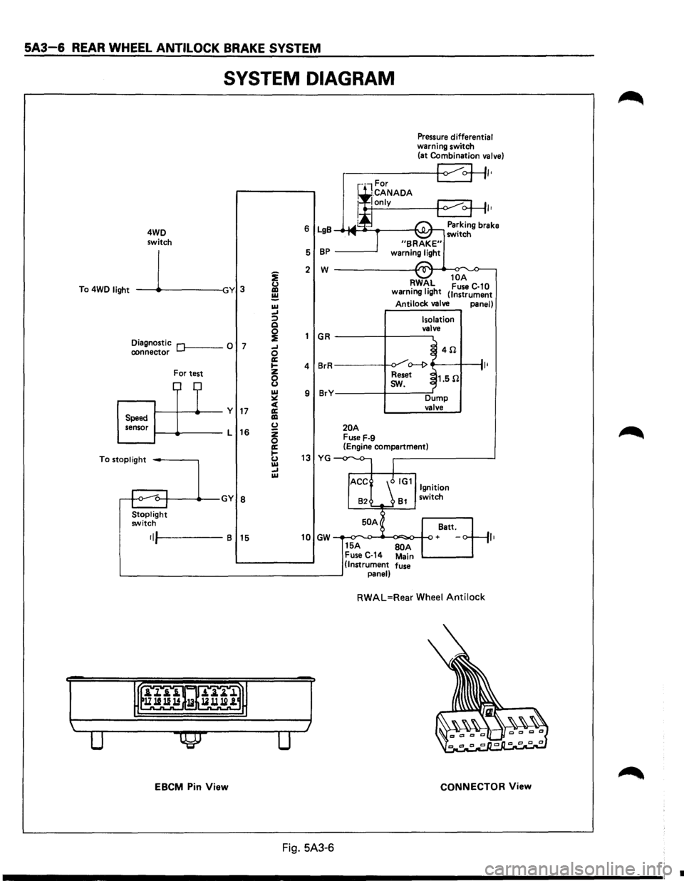
The EBCM operates by receiving signals from the
speed sensor (which
is located in the differential
carrier), combination
valve and the brake light switch.
The RWAL system is connected
to the RWAL indicator
light located on the dash. An indication of the RWAL
operation and a
bulb check is performed each time the
ignition is turned
"ON". The indicator light will remain
on
for about two seconds. A RWAL system
malfunction is indicated if the RWAL indicator light
stays on, or comes on during driving. To determine the
specific
trouble, refer to "RWAL System Diagnostics"
in this section.
Page 371 of 1928
REAR WHEEL ANTILOCK BRAKE SYSTEM 5A3-3
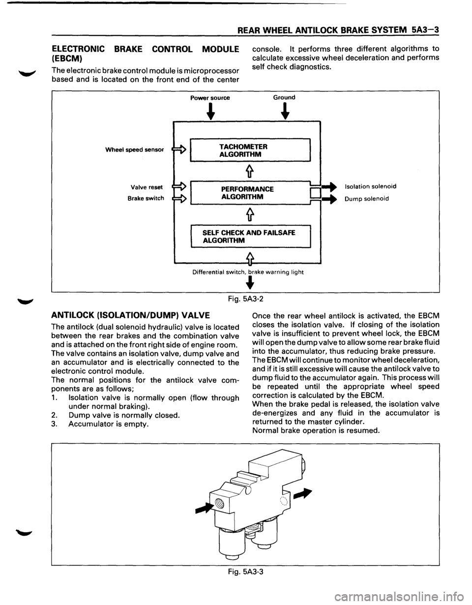
ELECTRONIC BRAKE CONTROL MODULE
(EBCM)
The electronic brake control module is microprocessor
based and is located on the
front end of the center
Power source
console. It performs three different algorithms to
calculate excessive wheel deceleration and performs
self check diagnostics.
Ground
~
Wheel speed sensor TACHOMETER
ALGORITHM
Valve reset
Brake
switch
PERFORMANCE
ALGORITHM o-+ ...
Isolation solenoid
Dump solenoid
SELF CHECK AND FAILSAFE
ALGORITHM
Differential switch, br<'!ke warning light
~
Fig. 5A3-2
ANTILOCK (ISOLATION/DUMP) VALVE
The antilock (dual solenoid hydraulic) valve is located
between the rear brakes and the combination valve
and is attached on the
front right side of engine room.
The valve contains
an isolation valve, dump valve and
an accumulator and is electrically connected to the
electronic control module.
The normal positions
for the antilock valve com
ponents are
as follows;
1. Isolation valve is normally open (flow through
under normal braking).
2. Dump valve is normally closed.
3. Accumulator is empty.
Once the rear wheel antilock is activated, the EBCM
closes the isolation valve. If closing of the isolation
valve is insufficient to prevent wheel lock, the
EBCM
will open the dump valve to allow some rear brake fluid
into the accumulator, thus reducing brake pressure.
The
EBCM will continue to monitor wheel deceleration,
and
if it is still excessive will cause the antilock valve to
dump fluid to the accumulator again. This process will
be repeated until the appropriate wheel speed
correction is calculated by the
EBCM.
When the brake pedal is released, the isolation valve
de-energizes and any fluid in the accumulator is
returned to the master cylinder.
Normal brake operation is resumed.
Fig. 5A3-3
Page 373 of 1928
REAR WHEEL ANTILOCK BRAKE SYSTEM 5A3-5
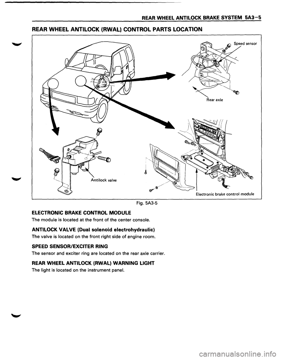
REAR WHEEL ANTILOCK (RWAL} CONTROL PARTS LOCATION
Fig. 5A3-5
ELECTRONIC BRAKE CONTROL MODULE
The module is located at the front of the center console.
ANTILOCK VALVE (Dual solenoid electrohydraulic)
The valve is located on the front right side of engine room.
SPEED SENSOR/EXCITER RING
The sensor and exciter ring are located on the rear axle carrier.
REAR WHEEL ANTILOCK (RWAL) WARNING LIGHT
The light is located on the instrument panel.
Rear axle
Electronic
brake control module
Page 374 of 1928
5A3-6 REAR WHEEL ANTILOCK BRAKE SYSTEM
SYSTEM DIAGRAM
4WD
switch
To 4WD
light -----11~-----lGY 3
Diagnostic Of------0 7 connector
For test
1-----11---+--y 17 Speed
sensor 1-----lt-----L
16
To
stoplight -----,
Stoplight switch
•IJI-----B 15
EBCM Pin View
i
&l ~ IU _, :;) Q
~ _, 0 a: .... z
8 IU ~ c( a: liD (.) z 0 a: 1-(.) IU _, IU
Pressure differential warning switch
(at Combination valve)
r-----+-<1 ~+II•
I•
6 LgB Parking brake _.-MI ____ ___,I'\.JI.Jr-, switch
5
BP -----'
2 w ------------~~._~
GR
4 BrR
9 BrY
20A Fuse F-9
RWAL 10
A •
1• h Fuse C-10
warnmg IQ t (Instrument
Antilock valve panel)
Isolation
valve
~ 4il .J o--1> ~
Reset ~1.5il
I
sw.
Dump valve
(Engine compartment)
13 YG -
82 81 switch
50 A
Batt.
10 GW + ,,
15A BOA Fuse C-14 Main (Instrument fuse panel)
RWAL=Rear Wheel Antilock
CONNECTOR View
Fig. 5A3-6
•
Page 375 of 1928
REAR WHEEL ANTILOCK BRAKE SYSTEM 5A3-7
REAR WHEEL ANTILOCK (RWAL) SYSTEM DIAGNOSTICS
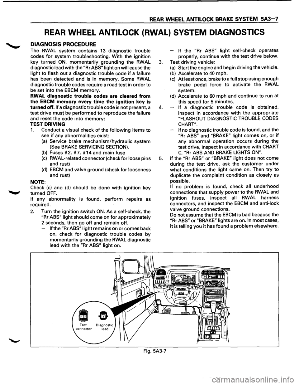
DIAGNOSIS PROCEDURE
The RWAL system contains 13 diagnostic trouble
codes
for system troubleshooting. With the ignition
key turned
ON, momentarily grounding the RWAL
diagnostic lead
with the "Rr ABS" light on will cause the
light
to flash out a diagnostic trouble code if a failure
has been detected and is in memory.
Some RWAL
diagnostic trouble codes require a road test in order
to
be set into the EBCM memory.
RWAL diagnostic trouble codes are cleared from
the
EBCM memory every time the ignition key is
turned off. If a diagnostic trouble code is not present, a
test drive
must be performed to reproduce the failure
and reset the code into
memory:
TEST DRIVING
1. Conduct a visual check of the following items to
see if any abnormalities exist:
(a) Service brake mechanism/hydraulic system
(See BRAKE SERVICING SECTION).
(b) Fuses #2, #7, #14 and main fuse
(c) RWAL-related connector (check for loose pins
and rust)
(d) EBCM and valve ground (check for looseness
and rust)
NOTE:
Check
(c) and (d) should be done with ignition key
turned
OFF.
If any abnormality is found, perform repairs as
required.
2. Turn the ignition switch ON. As a self-check, the
"Rr ABS" light should come on for approximately
2 seconds, then go
off and remain off.
If the "Rr ABS" light remains on or comes back
on, check
for diagnostic trouble codes by
momentarily grounding the RWAL diagnostic
lead
with the "Rr ABS" light on. -
If the "Rr
ABS" light self-check operates
properly, continue
with the test drive below.
3. Test driving vehicle:
(a) Start the engine and begin driving the vehicle.
(b) Accelerate to 40 mph.
(c) At least once, brake to a full stop using enough
brake pedal force
to activate the RWAL
system.
(d) Accelerate to 60 mph and continue to run at
this speed
for 5 minutes.
4. If a diagnostic trouble code is obtained.
inspect in accordance
with the appropriate
"FLASHOUT DIAGNOSTIC TROUBLE CODES
CHART".
If
no diagnostic trouble code is found, and the
"Rr ABS" and "BRAKE" light comes on, or if
any abnormal operation occurs during the
test drive, inspect in accordance
with CHART
C, "Rr ABS AND BRAKE LIGHTS ON".
5. If the "Rr ABS" or "BRAKE" light does not come
during the test drive, ask the customer under
what conditions the light came on. Then try to
duplicate the complaint condition
as closely as
possible.
If no problem is found, check all underhood
connections that supply power
to the RWAL and
ignition fuses, inspect
all RWAL harness
connectors, and inspect the
EBCM and anti-lock
valve ground connections.
Do not assume that the
EBCM is bad because the
"Rr ABS" or "BRAKE" lights are on. In most cases,
it is telling you it has found a problem elsewhere.
Fig. 5A3-7
Page 377 of 1928
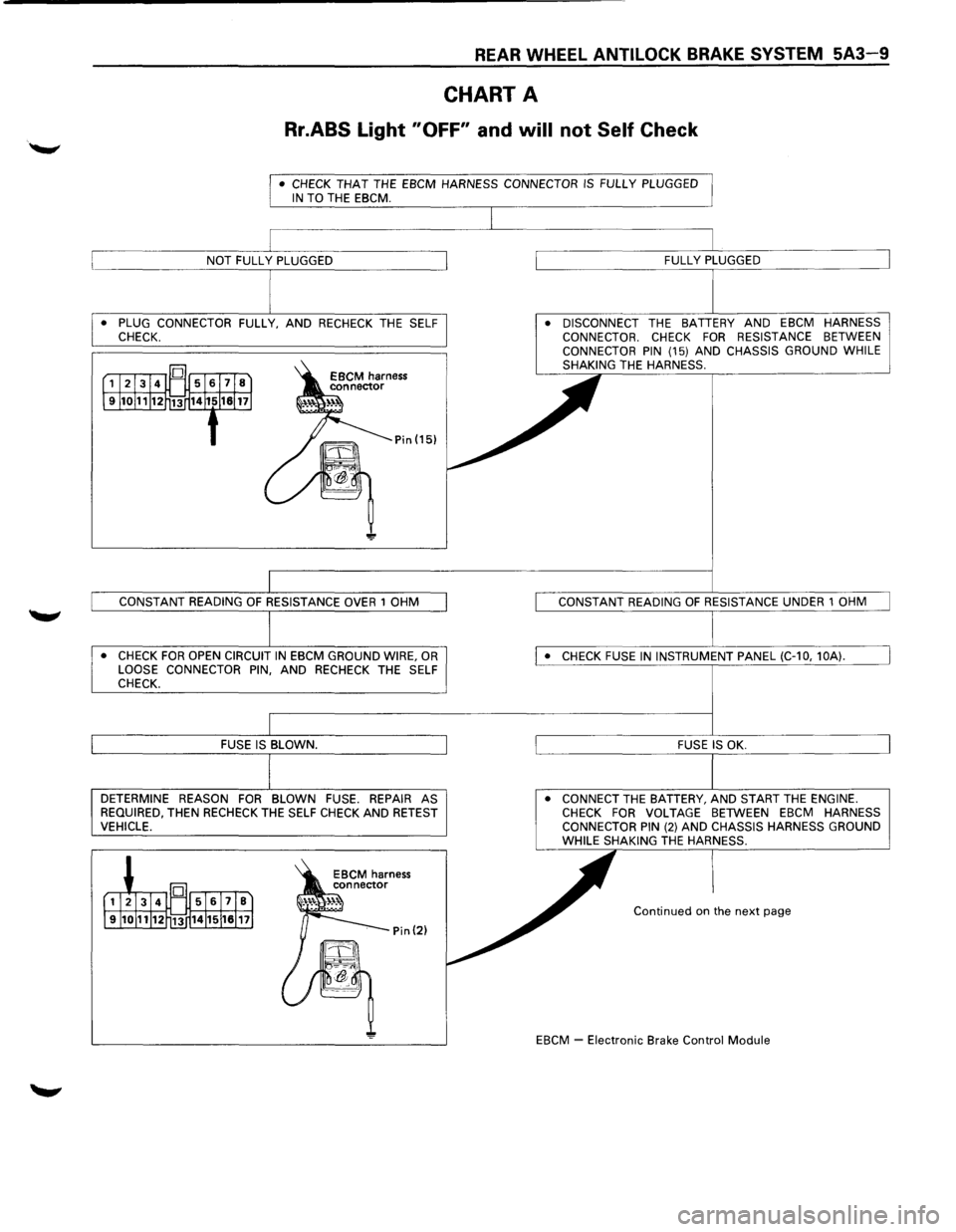
REAR WHEEL ANTILOCK BRAKE SYSTEM 5A3-9
CHART A
Rr.ABS Light "OFF" and will not Self Check
• CHECK THAT THE EBCM HARNESS CONNECTOR IS FULLY PLUGGED IN TO THE EBCM.
• PLUG CONNECTOR FULLY, AND RECHECK THE SELF
CHECK.
• CHECK FOR OPEN CIRCUIT IN EBCM GROUND WIRE, OR LOOSE CONNECTOR PIN, AND RECHECK THE SELF
CHECK.
DETERMINE REASON FOR BLOWN FUSE. REPAIR AS
REQUIRED, THEN RECHECK THE SELF CHECK AND RETEST VEHICLE. •
DISCONNECT
THE BATTERY AND EBCM HARNESS
CONNECTOR. CHECK FOR RESISTANCE BETWEEN
CONNECTOR PIN (15) AND CHASSIS GROUND WHILE
SHAKING THE HARNESS.
• CONNECT THE BATTERY, AND START THE ENGINE. CHECK FOR VOLTAGE BETWEEN EBCM HARNESS
CONNECTOR PIN (2) AND CHASSIS HARNESS GROUND WHILE SHAKING THE HARNESS.
Continued on the next page
EBCM
~ Electronic Brake Control Module
Page 379 of 1928
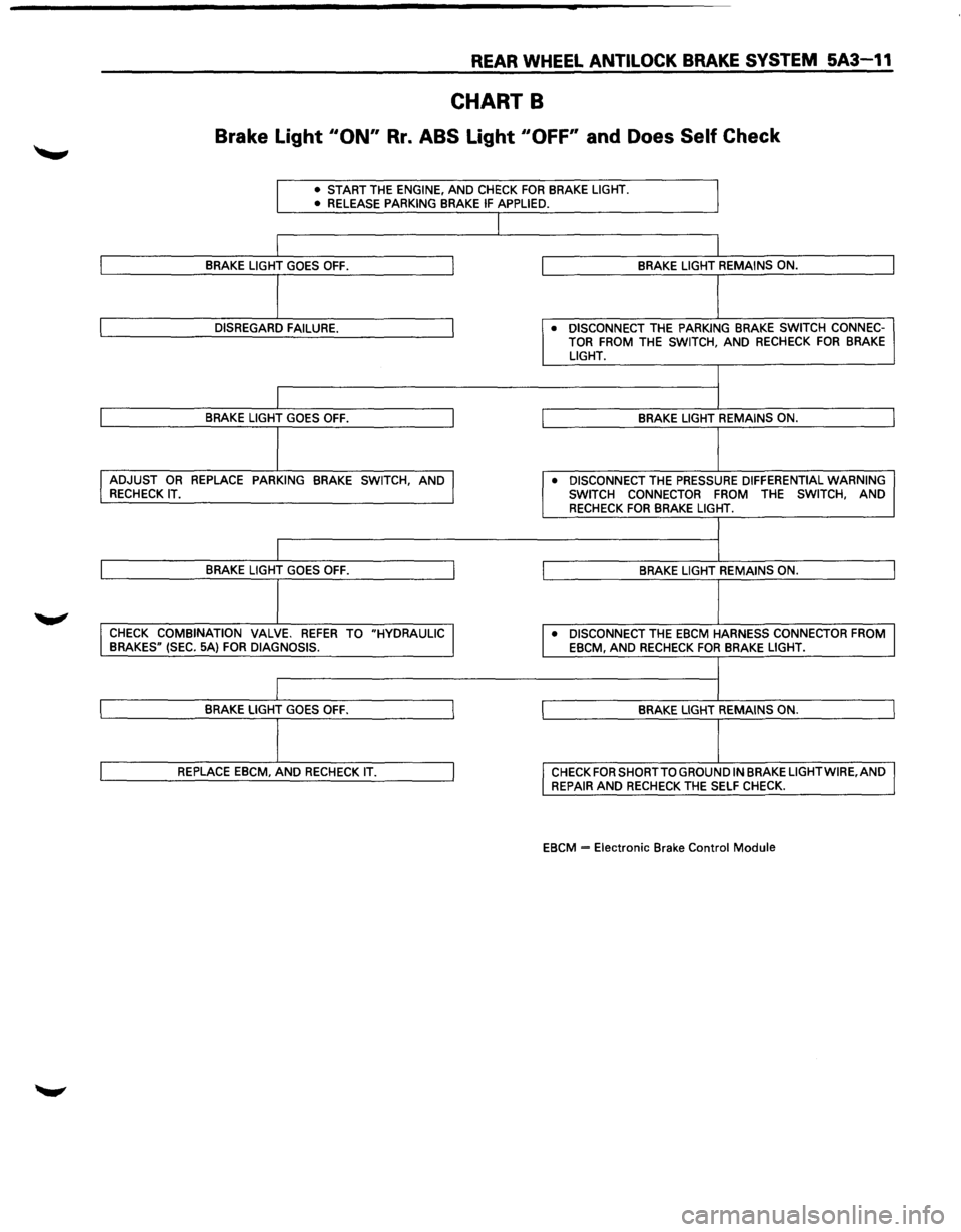
REAR WHEEL ANTILOCK BRAKE SYSTEM 5A3-11
CHART B
Brake Light 110N" Rr. ABS Light "OFF' and Does Self Check
• START THE ENGINE, AND CHECK FOR BRAKE LIGHT.
• RELEASE PARKING BRAKE IF APPLIED.
J
I
I BRAKE LIGHT GOES OFF. J BRAKE LIGHT REMAINS ON.
I
I DISREGARD FAILURE. J • DISCONNECT THE PARKING BRAKE SWITCH CONNEC-
TOR FROM THE SWITCH, AND RECHECK FOR BRAKE LIGHT.
I
I
I BRAKE LIGHT GOES OFF. I BRAKE LIGHT REMAINS ON.
I I ADJUST OR REPLACE PARKING BRAKE SWITCH, AND J • DISCONNECT THE PRESSURE DIFFERENTIAL WARNING RECHECK IT.
SWITCH CONNECTOR
FROM THE SWITCH, AND RECHECK FOR BRAKE LIGHT.
I
I
I BRAKE LIGHT GOES OFF. I BRAKE LIGHT REMAINS ON.
j
I CHECK COMBINATION VALVE. REFER TO "HYDRAULIC I • DISCONNECT THE EBCM HARNESS CONNECTOR FROM
BRAKES" (SEC. 5A) FOR DIAGNOSIS.
EBCM, AND RECHECK FOR BRAKE LIGHT.
I
I
I BRAKE LIGHT GOES OFF. I BRAKE LIGHT REMAINS ON.
I
I REPLACE EBCM, AND RECHECK IT. I CHECK FOR SHORT TO GROUND IN BRAKE LIGHTWIRE,AND
REPAIR AND RECHECK THE SELF CHECK.
EBCM
= Electronic Brake Control Module