brake ISUZU TROOPER 1995 Workshop Manual
[x] Cancel search | Manufacturer: ISUZU, Model Year: 1995, Model line: TROOPER, Model: ISUZU TROOPER 1995Pages: 1928
Page 487 of 1928
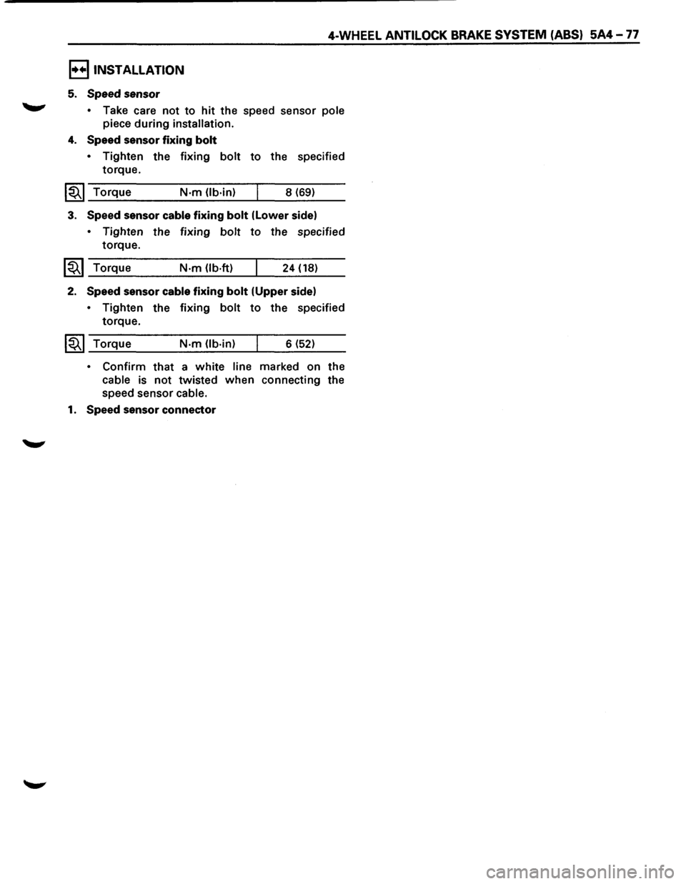
I••! INSTALLATION
5. Speed sensor
4-WHEEL ANTILOCK BRAKE SYSTEM (ABS) 5A4-77
,.....,. • Take care not to hit the speed sensor pole
piece during installation.
4. Speed sensor fixing bolt
• Tighten the fixing bolt to the specified
torque.
1~1 Torque N·m (lb·in) 8 (69)
3. Speed sensor cable fixing bolt (lower side)
• Tighten the fixing bolt to the specified
torque.
~~~ Torque N·m (lb-ft) 24 (18)
2. Speed sensor cable fixing bolt (Upper side)
• Tighten
torque.
1~1 Torque the
fixing
bolt to the specified
N-m (lb·in) 6 (52)
• Confirm that a white line marked on the
cable is not twisted when connecting the
speed sensor
cable.
1. Speed sensor connector
Page 488 of 1928
5A4-78 4-WHEEL ANTILOCK BRAKE SYSTEM (ABS)
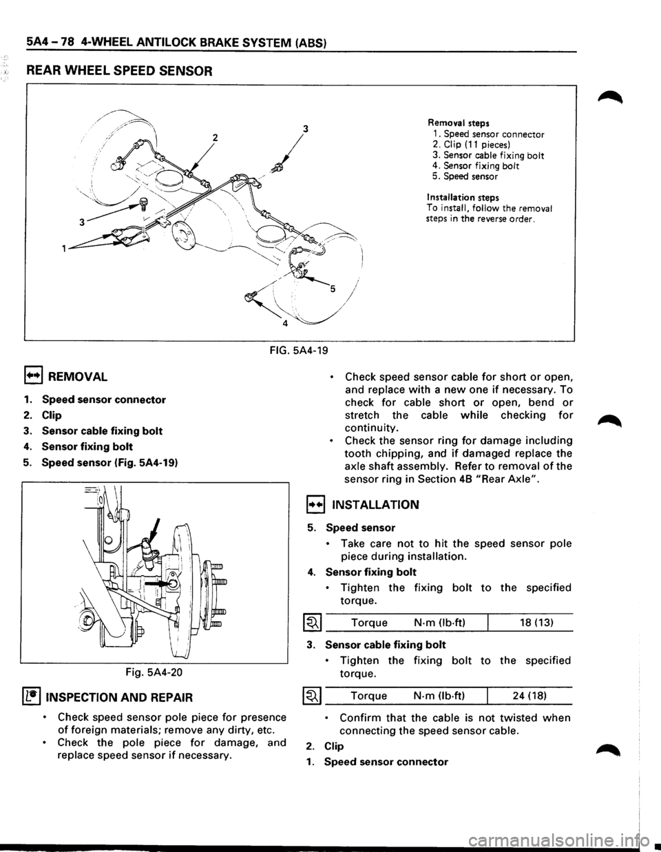
REAR WHEEL SPEED SENSOR
3 Removal steps
2
/
1. Speed sensor connector 2. Clip (11 pieces)
3.
Sensor cable fixing bolt 4. Sensor fixing bolt 5. Speed sensor
j
/
Installation steps
To
install, follow the removal
steps in the reverse order.
FIG. 5A4-19
1+•1 REMOVAL
1. Speed sensor connector
2. Clip
3. Sensor cable fixing bolt
4. Sensor fixing bolt
5. Speed sensor (Fig. 5A4-19)
Fig.
5A4-20
IL•ItNSPECTION AND REPAIR
• Check speed sensor pole piece for presence
of foreign materials; remove any dirty, etc.
• Check the pole piece for damage, and
replace speed sensor if necessary.
• Check speed sensor cable for short or open,
and
replace with a new one if necessary. To
check
for cable short or open, bend or
stretch the cable while checking for
continuity.
• Check the sensor ring for damage including
tooth chipping, and if damaged replace the
axle shaft assembly. Refer to removal of the
sensor ring in
Section 48 "Rear Axle".
,,..,,INSTALLATION
5. Speed sensor
• Take care not to hit the speed sensor pole
piece during installation.
4. Sensor fixing bolt
• Tighten the fixing bolt to the specified
torque.
I~I ____ T_o_rq~u_e ____ N __ ·m __ O_b·_ft_) __ ~ ____ 18_(_1_3_) __
3. Sensor cable fixing bolt
• Tighten the fixing bolt to the specified
torque.
~~~ Torque N·m (lb.ft) 24 (18)
• Confirm that the cable is not twisted when
connecting the speed sensor cable.
2. Clip
1. Speed sensor connector
•
Page 489 of 1928
ILLUSTRATION
'~ ~··
J -
~
. .
"
~
"f'38~
0
~~ '~
--~ S::S.·f
-~; -~b'
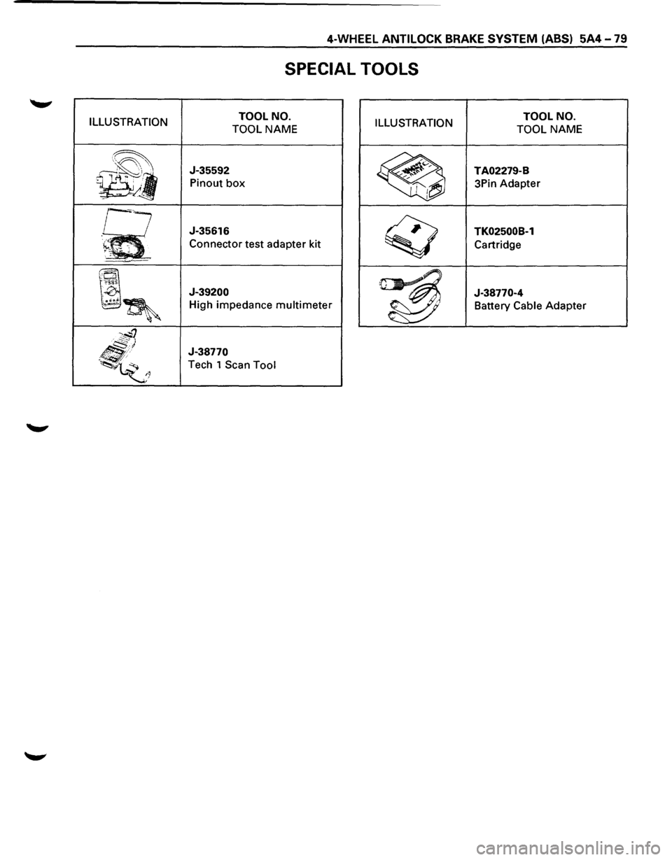
SPECIAL TOOLS
TOOL NO.
TOOL
NAME ILLUSTRATION
J-35592
Pinout box
J-35616
Connector test adapter kit
J-39200
High impedance multimeter
J-38770
Tech 1 Scan Tool
TOOL NO.
TOOL
NAME
TA02279-B
3Pin Adapter
TK02500B-1
Cartridge
J-38770-4 Battery
Cable Adapter
Page 491 of 1928
PARKING BRAKES 5C-1
SECTION 5C
PARKING BRAKES
'\f7 CAUTION:
Yf All brake attaching fasteners are an important attaching part in that they could affect performance of vital
parts and systems, and/or could result in major repair expense. They must be replaced with one ofthe same
part number
or with and equivalent part if replacement becomes necessary. Do not use replacement parts of
lesser quality or substitute design. Torque values must be used as specified during reassembly to assure
proper retention
of these parts.
CONTENTS
General Description ..................... 5C-1
Operation . . . . . . . . . . . . . . . . . . . . . . . . . . . . . 5C-2
On-Vehicle Service
..................... 5C-3
Parking Brake Lever Replacement . .
. . . . .
5C-3
Parking Brake Front Cable . .
. . . . . . . . . . .
5C-4
Parking Brake Rear Cable . .
. . . . . . . . . . . .
5C-5
Parking Brake Lining Inspection ......... 5C-6
Parking Brake Rotor (Drum) Inspection ... 5C-6
Parking Brake Adjustment .............. 5C-7
Main Data and Specifications ............. 5C-8
General
Specifications ................. 5C-8
Torque Specifications ................. 5C-8
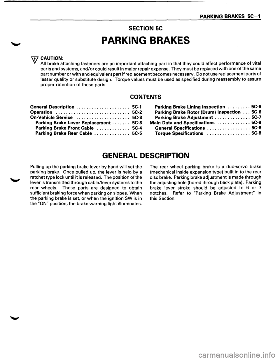
GENERAL DESCRIPTION
Pulling up the parking brake lever by hand will set the
parking brake.
Once pulled up, the lever is held by a
ratchet type
lock until it is released. The position of the
lever is transmitted through cable/lever systems to the
rear
wheels. These parts are designed to obtain
sufficient braking force
when parking on slopes. When
the parking brake is set,
or when the ignition SW is in
the
"ON" position, the brake warning light illuminates.
The rear wheel parking brake is a duo-servo brake
(mechanical inside expansion type) built in to the rear
disc brake. Parking brake adjustment is made through
the adjusting
hole (bored through back plate). Parking
brake
lever stroke should be adjusted to 6 or 7
notches. Refer
to "Parking Brake Adjustment" in
this Section.
Page 492 of 1928
5C-2 PARKING BRAKES
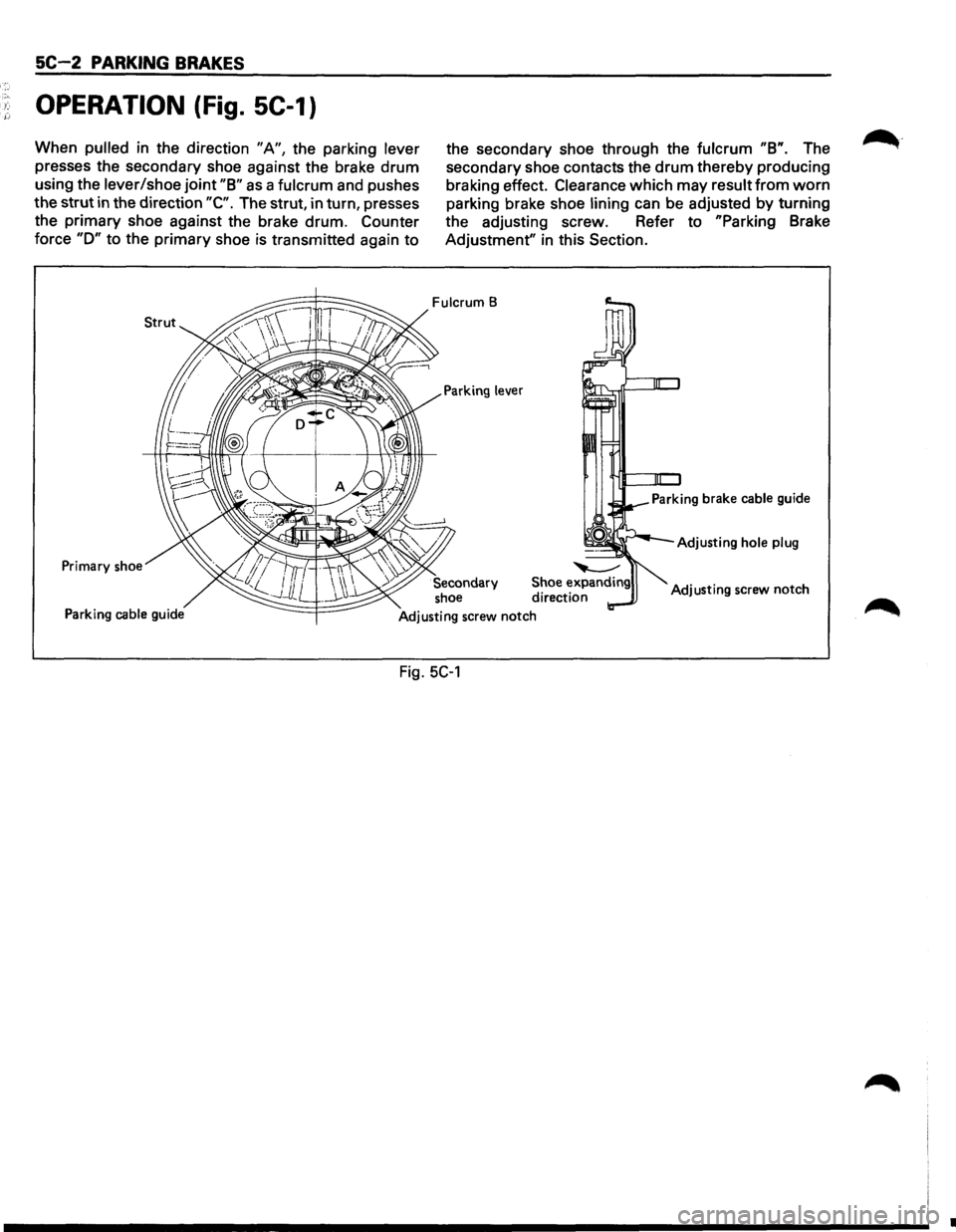
OPERATION (Fig. SC-1)
When pulled in the direction "A", the parking lever
presses the secondary shoe against the brake drum
using the lever/shoe joint "8" as a fulcrum and pushes
the strut in the direction
"C". The strut, in turn, presses
the primary shoe against the brake drum.
Counter
force "D" to the primary shoe is transmitted again to
Primary shoe
Parking cable guide
the secondary shoe through the fulcrum "8". The
secondary shoe contacts the
drum thereby producing
braking effect.
Clearance which may result from worn
parking brake shoe lining can be adjusted by turning
the adjusting screw. Refer to
"Parking Brake
Adjustment"
in this Section.
Fulcrum B
Adjusting hole plug
Adjusting screw notch
Fig. 5C-1
•
Page 493 of 1928
~
PARKING BRAKES SC-3
ON-VEHICLE SERVICE
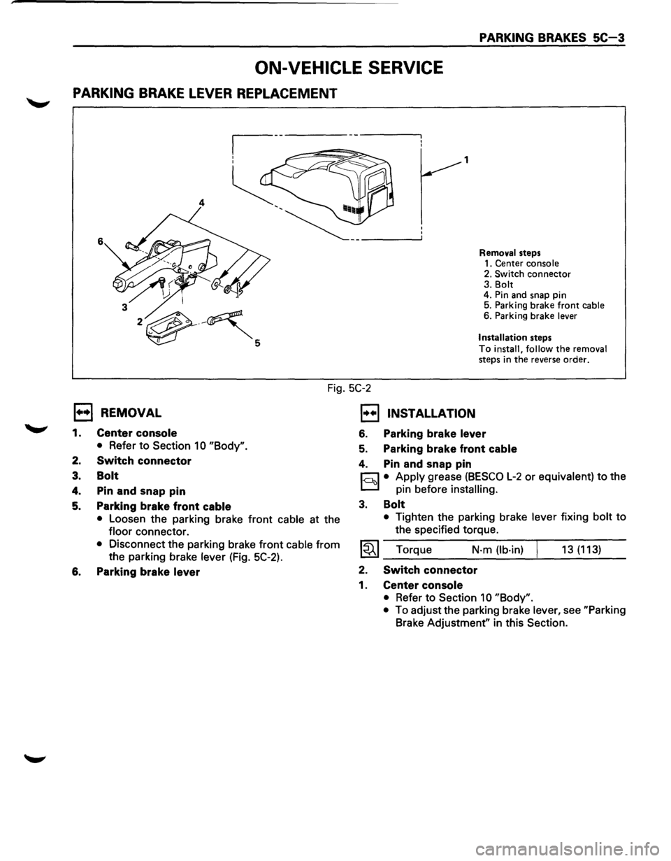
PARKING BRAKE LEVER REPLACEMENT
1
4
6
Removal steps
1. Center console
2. Switch
connector 3. Bolt
4. Pin and snap pin
5. Parking brake
front cable 6. Parking brake lever
Installation
steps
To install, follow the removal
steps in the reverse order.
Fig. 5C-2
l••l REMOVAL
1.
2.
3.
4.
5.
Center console
• Refer to Section 1 0 "Body".
Switch connector
Bolt
Pin and snap pin
Parking brake front
cable
• Loosen the parking brake front cable at the
floor connector.
• Disconnect the parking brake front cable from
the parking brake lever (Fig. 5C-2).
6. Parking brake lever
1••1 INSTALLATION
6. Parking brake lever
5. Parking brake front cable
4. Pin and snap pin
r:::J • Apply grease (BESCO L-2 or equivalent) to the
D pin before installing.
3. Bolt
• Tighten the parking brake lever fixing bolt to
the specified torque.
~~~ Torque N·m (lb·in) 13 (113)
2. Switch connector
1. Center console
• Refer to Section 10 "Body".
•
To adjust the parking brake lever, see "Parking
Brake Adjustment" in this Section.
Page 494 of 1928
5C-4 PARKING BRAKES
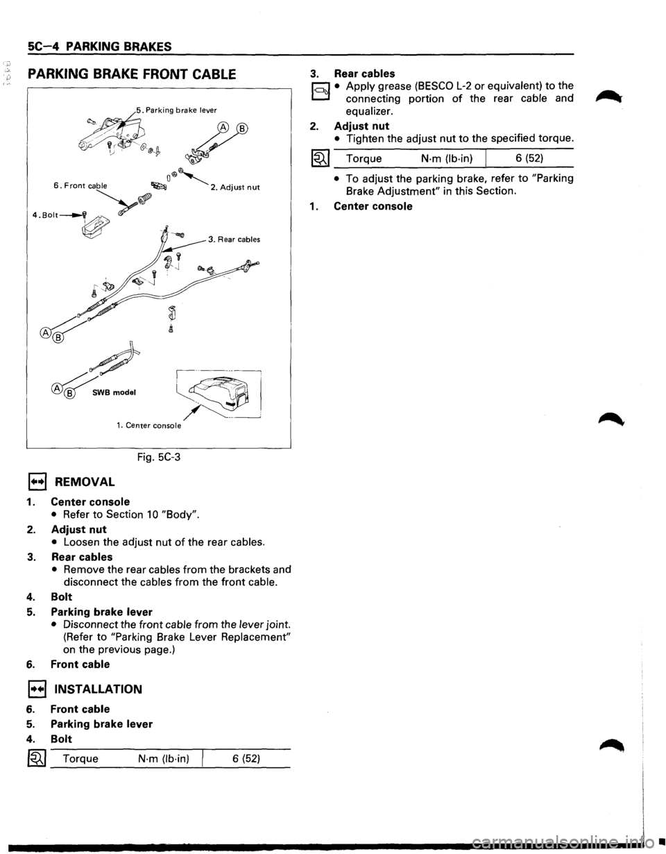
PARKING BRAKE FRONT CABLE
<.~ '"''"' brnke '""" ~
~~~ ~ ~
o®~ 6. Front cable ~ 2. Adjust nut
··"""-v>.?
~
~
#
~WBmodel
,----~
~~
~ ~--___j 1. Center console
Fig. 5C-3
1••1 REMOVAL
1. Center console
• Refer to Section 10 "Body".
2. Adjust nut
• Loosen the adjust nut of the rear cables.
3. Rear cables
• Remove the rear cables from the brackets and
disconnect the cables
from the front cable.
4. Bolt
5. Parking brake lever
• Disconnect the front cable from the lever joint.
(Refer to
"Parking Brake Lever Replacement"
on the previous page.)
6. Front cable
1•+1 INSTALLATION
6. Front cable
5.
4.
Parking brake lever
Bolt
I~I_T_o_rq_u_e ___ N_·_m_(lb_·_in_) --'---6_(_5_2) __
3. Rear cables
r;:::;:] • Apply grease (BESCO L-2 or equivalent) to the
D connecting portion of the rear cable and
equalizer.
2. Adjust nut
• Tighten the adjust nut to the specified torque.
~~~ Torque N-m (lb-in) J 6 (52)
• To adjust the parking brake, refer to "Parking
Brake
Adjustment" in this Section.
1 . Center console
•
Page 495 of 1928
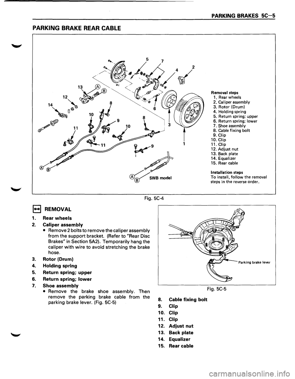
PARKING BRAKE REAR CABLE
1
v9
;#
~SWBmodel
Fig. 5C-4
E) REMOVAL
1. Rear wheels
2. Caliper assembly
• Remove 2 bolts to remove the caliper assembly
from the support bracket. (Refer to "Rear Disc
Brakes" in
Section 5A2). Temporarily hang the
caliper with wire to avoid stretching the brake
hose.
3. Rotor (Drum)
4.
Holding spring
5. Return spring; upper
6. Return spring; lower
7. Shoe assembly
• Remove the brake shoe assembly. Then
remove the parking brake
cable from the
parking brake
lever. (Fig. 5C-5) 8.
9.
10.
11.
12.
13.
14. 15.
Cable fixing bolt
Clip
Clip
Clip
Adjust nut
Back
plate
Equalizer
Rear cable
PARKING BRAKES SC-5
Removal steps
1. Rear wheels
2. Caliper assembly 3. Rotor (Drum)
4. Holding spring 5. Return spring; upper
6. Return spring; lower 7. Shoe assembly 8. Cable fixing bolt 9. Clip 10.Ciip 11. Clip
12. Adjust nut 13. Back plate 14. Equalizer 15. Rear cable
Installation
steps To install, follow the removal steps in the reverse order.
Parking brake lever
Fig. SC-5
Page 496 of 1928
5C-6 PARKING BRAKES
1••1 INSTALLATION
15. Rear cable
hl • Apply grease (BESCO L-2 or equivalent) to the
D connecting portion of the rear cable and
equalizer.
14. Equalizer
13. Back plate
12. Adjust nut
• Tighten the adjust nut to the specified torque.
1~1 Torque N-m (lb-in) I 6 (52)
• To adjust the parking brake, refer to "Parking
Brake Adjustment" in this Section.
11,10, 9. Clip
~~~ Torque N·m (lb·in) I 6 (52)
8. Cable fixing bolt
• Tighten the cable fixing bolt to the specified
torque.
~~~ Torque N·m (lb·in) 6 (52)
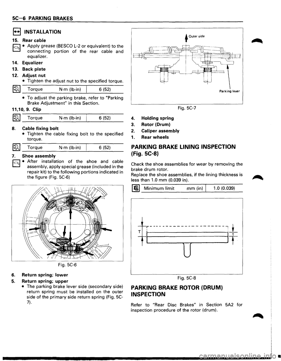
7. Shoe assembly
h1 • After installation of the shoe and cable
D assembly, apply special grease (included in the
repair kit)
to the following portions indicated in
the figure (Fig.
5C-6)
Fig. 5C-6
6. Return spring; lower
5. Return spring; upper
• The parking brake lever side (secondary side)
return spring
must be installed on the outer
side
of the primary side return spring (Fig. 5C-
7).
+Outer side
Fig. 5C-7
4. Holding spring
3. Rotor (Drum)
2. Caliper assembly
1. Rear wheels
Parking lever
PARKING BRAKE LINING INSPECTION
(Fig. SC-8)
Check the shoe assemblies for wear by removing the
brake
drum rotor.
Replace the shoe assemblies, if the lining thickness is
less than 1.0 mm (0.039 in).
1@1 Minimum limit mm (in) J 1.0 (0.039)
-1---r-----------------------,_1_ . '
T I It
u
Fig. 5C-8
PARKING BRAKE ROTOR (DRUM)
INSPECTION
Refer to "Rear Disc Brakes" in Section 5A2 for
inspection procedure
of the rotor (drum).
•
Page 497 of 1928
PARKING BRAKE ADJUSTMENT
1. Adjustment of parking brake assembly
• Prior to lever stroke adjustment, adjust the rear
brake
shoe/rotor (drum) gap. Perform this
procedure
by loosening the adjust nut of the
equalizer.
a) Remove the adjusting hole plug (rubber) and
turn the shoe adjusting screw
downward with a
small screwdriver so that shoes will expand
until
they get into close touch with the rotor.
(Turn
down the adjusting screw notch by notch
until the rotor does not turn.)
b) Turn the adjusting screw in the opposite
direction (upward) until the rotor can
be turned
lightly. Standard
number of notches to turn
upward: 7 or 8.
Turn the rotor and make sure that there is no
brake dragging.
2. Adjustment of parking brake cable
a) Turn the equalizer nut so that the parking brake
lever travels 6
or 7 notches when pulled up with
a force of 30 kg (66 lb).
b) Make sure there is no brake dragging and
tighten the cable lock nut.
l~l Torque N·m (lb·in) 6 (52)
3. Break-in of parking brake shoe
• When poor braking effect possibly resulting
from insufficient break-in is felt, or just after
replacement
of parking brake shoe, be sure to
conduct break-in by driving vehicle as follows:
a) Forward 50 km/h (30 mph) x 400 m (About 30
seconds) with a lever pull force of 15 kg (33 lb),
and
b) Backward 10 km/h (6 mph) x 50 m (18 sec-
onds)
with a lever pull force of 15 kg (33 lb).
NOTE:
Break-in procedure must be performed under the
safety conditions and traffic rules.
• If braking effect still remains poor after the
above break-in,
wait for some time until
parking brake shoe cools
down and repeat the
procedures
a) and b) noted above.
• On completion of break-in, inspect parking
brake lever stroke, and
if the lever does not
come within the specified number of notches
when pulled up, readjust.
• Excessive brake-in may cause premature wear
of the parking brake lining.
PARKING BRAKES SC-7