brake ISUZU TROOPER 1995 Workshop Manual
[x] Cancel search | Manufacturer: ISUZU, Model Year: 1995, Model line: TROOPER, Model: ISUZU TROOPER 1995Pages: 1928
Page 935 of 1928
AUTOMATIC TRANSMISSION (4L30-E) 7 A-63
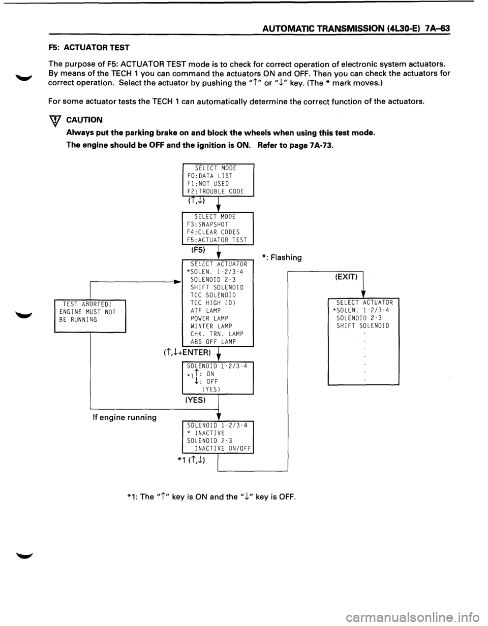
F5: ACTUATOR TEST
The purpose
of F5: ACTUATOR TEST mode is to check for correct operation of electronic system actuators.
By means of the TECH 1 you can command the actuators ON and OFF. Then you can check the actuators for
correct operation.
Select the actuator by pushing the "i" or".!." key. (The* mark moves.)
For some actuator tests the TECH 1
can automatically determine the correct function of the actuators.
W CAUTION
Always put the parking brake on and block the wheels when using this test mode.
The engine
should be OFF and the ignition is ON. Refer to page 7A-73.
TEST ABORTED! ENGINE MUST NOT BE RUNNING
If engine running
SELECT MODE FO: DATA LIST
F1:NOT USED F2:TROUBLE CODE
(T,.J..)
SELECT MODE
F3:SNAPSHOT F4:CLEAR CODES
F5:ACTUATOR TEST
(F5)
SELECT ACTUATOR *SOLEN. 1-2/3-4 SOLENOID 2-3
SHIFT SOLENOID TCC SOLENOID TCC HIGH CD)
ATF LAMP POWER LAMP WINTER LAMP
CHK. TRN. LAMP ABS OFF LAMP
(i,.!.+ENTER)
SOLENOID 1-2/3-4
*1 i: ON .j,: OFF
CYESJ
(YES)
SOLENOID 1-2/3-4 * INACTIVE SOLENOID 2-3 INACTIVE ON/OFF
* 1 (i,.!.)
*:Flashing
*1: The
"i" key is ON and the".!." key is OFF.
(EXIT)
SELECT ACTUATOR *SOLEN. 1-2/3-4 SOLENOID 2-3 SHIFT SOLENOID
Page 939 of 1928
AUTOMATIC TRANSMISSION (4L30-E) 7 A~7
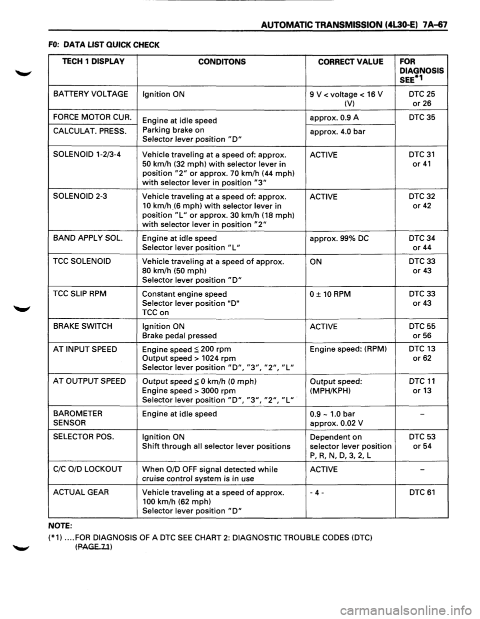
FO: DATA LIST QUICK CHECK
TECH 1
DISPLAY
CONDITONS CORRECT VALUE
BATIERY VOLTAGE
Ignition ON 9 V < voltage < 16 V
(V)
FORCE MOTOR CUR. Engine at idle speed approx. 0.9 A
CALCULAT. PRESS. Parking
brake on
approx. 4.0 bar Selector lever position "D"
SOLENOID 1-2/3-4
Vehicle traveling at a speed of: approx. ACTIVE
50 km/h (32 mph) with selector lever in
position
"2" or approx. 70 km/h (44 mph)
with selector lever in position "3"
SOLENOID 2-3
Vehicle traveling at a speed of: approx. ACTIVE
10 km/h_(6 mph) with selector lever in
position
"L" or approx. 30 km/h (18 mph)
with selector lever in position "2"
BAND APPLY SOL. Engine at idle speed
approx. 99% DC
Selector lever position "L"
TCC SOLENOID Vehicle traveling at a speed of approx. ON
80 km/h (50 mph)
Selector lever position "D"
TCC SLIP RPM Constant engine speed 0 ± 10 RPM
Selector lever position "D"
TCCon
BRAKE SWITCH
Ignition ON ACTIVE
Brake pedal pressed
AT
INPUT SPEED Engine speed :;:; 200 rpm Engine speed: (RPM)
Output speed> 1024 rpm
Selector lever position "D", "3", "2", "L"
AT OUTPUT SPEED Output speed:;:; 0 km/h (0 mph) Output speed:
Engine speed >
3000 rpm (MPH/KPH)
Selector lever position "D", "3", "2", "L" ·
BAROMETER
Engine at idle speed 0.9-1.0 bar
SENSOR approx. 0.02 V
SELECTOR POS. Ignition ON Dependent on
Shift through all selector lever positions selector lever position
P, R, N, D, 3, 2, L
C!C OlD LOCKOUT When 0/D OFF signal detected while ACTIVE
cruise control system is in use
ACTUAL GEAR Vehicle traveling at a speed of approx. - 4 -
100 km/h (62 mph)
Selector lever position
"D"
NOTE:
(*1) .... FOR DIAGNOSIS OF A DTC SEE CHART 2: DIAGNOSTIC TROUBLE CODES (DTC)
tPAGE..ll)
FOR
DIAGNOSIS
SEE*1
DTC25
or 26
DTC35
DTC 31
or 41
DTC32
or 42
DTC34
or 44
DTC33
or 43
DTC33
or 43
DTC55
or 56
DTC 13
or 62
DTC 11
or13
-
DTC53
or 54
-
DTC 61
Page 943 of 1928
AUTOMATIC TRANSMISSION (4L30-E) 7 A-71
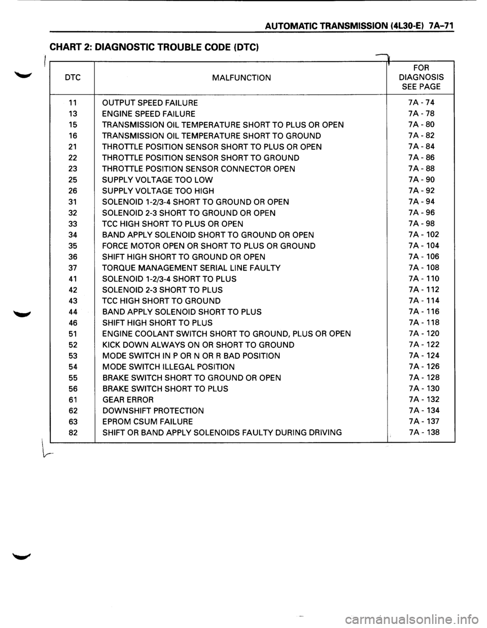
CHART 2: DIAGNOSTIC TROUBLE CODE (OTC)
I v
' FOR
DTC MALFUNCTION DIAGNOSIS
SEE PAGE
11 OUTPUT
SPEED FAILURE 7A -74
13 ENGINE SPEED FAILURE 7A -78
15 TRANSMISSION OIL TEMPERATURE SHORT TO PLUS OR OPEN 7A-80
16 TRANSMISSION OIL TEMPERATURE SHORT TO GROUND 7A-82
21 THROTTLE POSITION SENSOR SHORT TO PLUS OR OPEN 7A-84
22 THROTTLE POSITION SENSOR SHORT TO GROUND 7A-86
23 THROTTLE
POSITION SENSOR CONNECTOR OPEN 7A-88
25
SUPPLY VOLTAGE TOO LOW 7A-90
26 SUPPLY VOLTAGE TOO HIGH 7A-92
31 SOLENOID 1-2/3-4 SHORT TO GROUND OR OPEN 7A-94
32
SOLENOID 2-3 SHORT TO GROUND OR OPEN 7A-96
33 TCC
HIGH SHORT TO PLUS OR OPEN 7A-98
34
BAND APPLY SOLENOID SHORT TO GROUND OR OPEN 7A-102
35 FORCE MOTOR OPEN OR SHORT TO PLUS OR GROUND 7A-104
36 SHIFT HIGH SHORT TO GROUND OR OPEN 7A-106
37 TORQUE MANAGEMENT SERIAL LINE FAULTY 7A-108
41 SOLENOID 1-2/3-4 SHORT TO PLUS 7A-110
42 SOLENOID 2-3 SHORT TO PLUS 7A-112
43 TCC HIGH SHORT TO GROUND 7A-114
44
BAND APPLY SOLENOID SHORT TO PLUS 7A-116
46 SHIFT HIGH SHORT TO PLUS 7A-118
51 ENGINE COOLANT SWITCH SHORT TO GROUND, PLUS OR OPEN 7A-120
52 KICK DOWN ALWAYS ON OR SHORT TO GROUND 7A-122
53 MODE SWITCH IN P OR N OR R BAD POSITION 7A-124
54
MODE SWITCH ILLEGAL POSITION 7A-126
55 BRAKE
SWITCH SHORT TO GROUND OR OPEN 7A-128
56 BRAKE
SWITCH
SHORT TO PLUS 7A-130
61 GEAR ERROR 7A-132
62 DOWNSHIFT PROTECTION 7A-134
63
EPROM CSUM FAILURE 7A-137
82 SHIFT OR BAND APPLY SOLENOIDS FAULTY DURING DRIVING 7A-138
Page 951 of 1928
AUTOMATIC TRANSMISSION (4L30-E) 7A-79
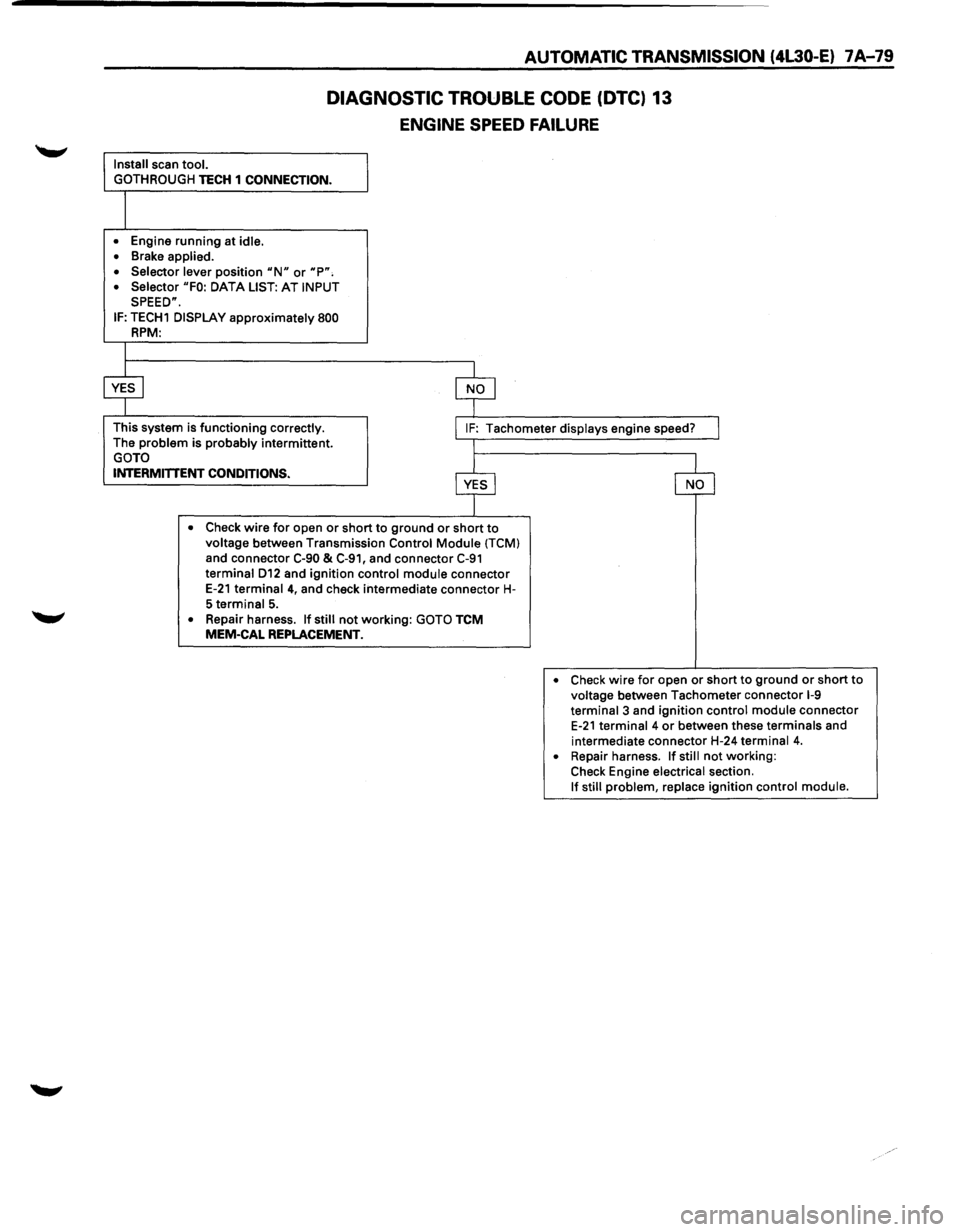
DIAGNOSTIC TROUBLE CODE (DTC) 13
ENGINE SPEED FAILURE
Install scan tool.
GOTHROUGH
TECH 1 CONNECTION.
I
• Engine running at idle.
• Brake applied.
• Selector lever
position "N" or "P", • Selector "FO: DATA LIST: AT INPUT SPEED".
IF: TECH1 DISPLAY approximately 800 RPM:
I
$
This system is functioning correctly. The problem is probably intermittent. GOTO
I IF: Tachometer displays engine speed? I
'~------------------~
$ c§J
INTERMITTENT CONDITIONS.
r---------------------------------~----~ • Check wire for open or short to ground or short to voltage between Transmission Control Module (TCM) and connector C-90 & C-91, and connector C-91 terminal D12 and ignition control module connector E-21 terminal 4, and check intermediate connector H-5 terminal 5.
• Repair harness. If still not working: GOTO TCM MEM-CAL REPLACEMENT.
• Check wire for open or short to ground or short to voltage between Tachometer connector 1-9 terminal 3 and ignition control module connector E-21 terminal 4 or between these terminals and
intermediate connector H-24
terminal 4. • Repair harness. If still not working: Check Engine electrical section. If still problem, replace ignition control module.
Page 970 of 1928
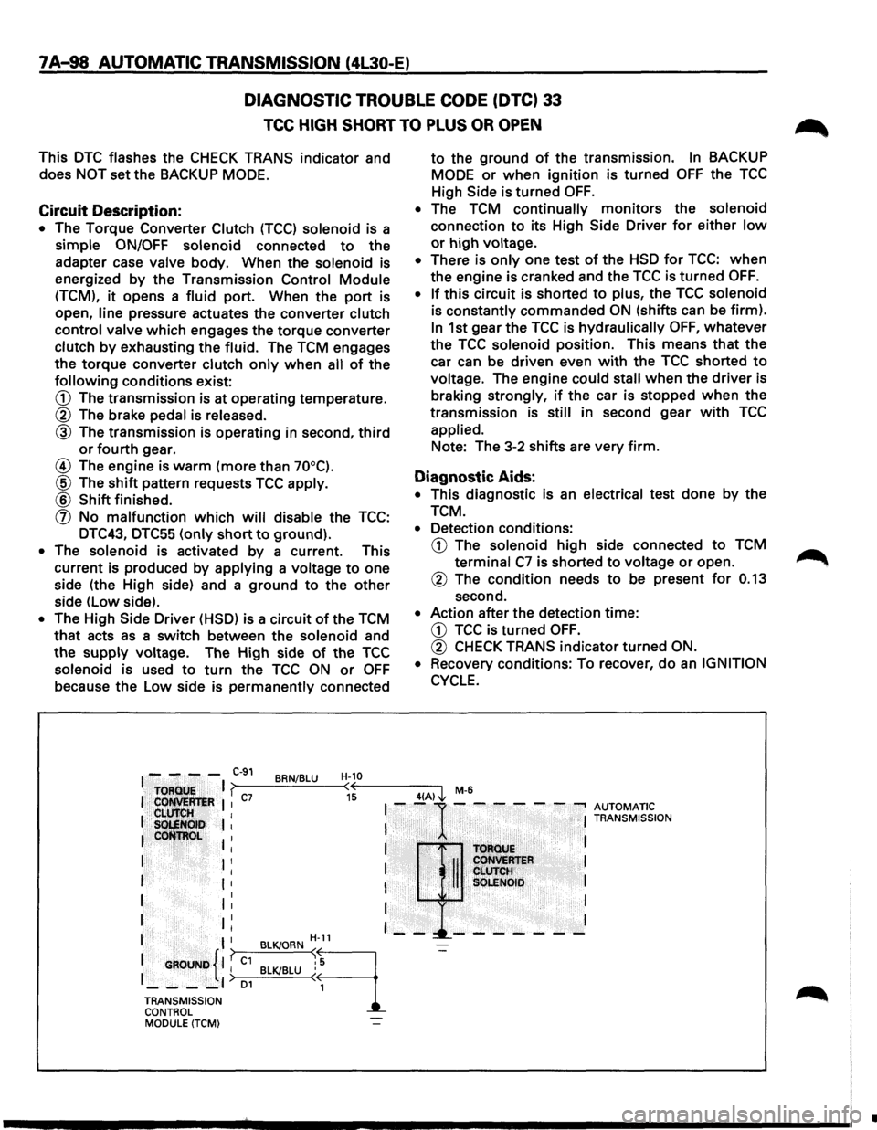
7 A-98 AUTOMATIC TRANSMISSION (4L30-E)
DIAGNOSTIC TROUBLE CODE (DTC) 33
TCC HIGH SHORT TO PLUS OR OPEN
This DTC flashes the CHECK TRANS indicator and
does NOT set the BACKUP MODE.
Circuit Description:
• The Torque Converter Clutch (TCC) solenoid is a
simple ON/OFF solenoid connected to the
adapter case valve body. When the solenoid is
energized
by the Transmission Control Module
(TCM), it opens a fluid port. When the port is
open,
line pressure actuates the converter clutch
control valve which engages the torque converter
clutch by exhausting the fluid. The TCM engages
the torque converter clutch only when all of the
following conditions exist:
G) The transmission is at operating temperature.
® The brake pedal is released.
® The transmission is operating in second, third
or fourth gear.
@ The engine is warm (more than 70°C).
® The shift pattern requests TCC apply.
® Shift finished.
(]) No malfunction which will disable the TCC:
DTC43, DTC55
(only short to ground).
• The solenoid is activated by a current. This
current is produced by applying a voltage to one
side (the High side) and a ground to the other
side (low side).
• The High Side Driver (HSD) is a circuit of the TCM
that acts as a switch between the solenoid and
the supply voltage. The High side of the TCC
solenoid is used to turn the TCC ON or OFF
because the Low side is permanently connected
to the ground of the transmission. In BACKUP
MODE
or when ignition is turned OFF the TCC
High Side is
turned OFF.
• The TCM continually monitors the solenoid
connection to its High Side Driver for either low
or high voltage.
• There is only one test of the HSD for TCC: when
the engine is cranked and the TCC is turned OFF.
•
If this circuit is shorted to plus, the TCC solenoid
is constantly commanded ON (shifts can be firm).
In 1st gear the TCC is hydraulically OFF, whatever
the TCC solenoid position. This means that the
car can be driven even with the TCC shorted to
voltage. The engine could stall when the driver is
braking strongly, if the car is stopped when the
transmission is still in second gear with TCC
applied. Note: The 3-2
shifts are very firm.
Diagnostic Aids:
• This diagnostic is an electrical test done by the
TCM.
• Detection conditions:
G) The solenoid high side connected to TCM
terminal C7 is shorted to voltage or open.
® The condition needs to be present for 0.13
second.
• Action after the detection time:
G) TCC is turned OFF.
® CHECK TRANS indicator turned ON.
•
Recovery conditions: To recover, do an IGNITION
CYCLE.
I - - - -C-91 BRN/BLU H-10
TOFlQU!;
I ? (( 4(A) J., M-6
I Cot!M:R'teR I I c7 15 I --1· -.-- - - ---. AUTOMATIC .. CLU'IrlilH I I S~NOib I I I TRANSMISSION
leoti~~~~ I . I I T()ftotJE
I I I I II CoHVEMER I I ' CLUTCH I I I I SQLENOID I
I 1: I I
I II I I I
I I H-11 - --!._-- - - - - -
{ I
{
BLK/ORN ~
9
-=-
1 GROUND I I C1 BLK/BLU : 5
1_--_,) 01 ( 1
TRANSMISSION
CONTROL MODULE (TCM)
•
Page 974 of 1928
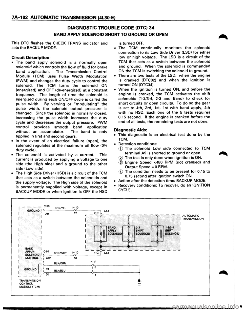
7A-102 AUTOMATIC TRANSMISSION (4L30-E)
DIAGNOSTIC TROUBLE CODE
(DTC) 34
BAND APPLY SOLENOID SHORT TO GROUND OR OPEN
This DTC flashes the CHECK TRANS indicator and
sets the BACKUP
MODE.
Circuit Description:
• The band apply solenoid is a normally open
solenoid
which controls the flow of fluid for brake
band
application. The Transmission Control
Module (TCM) uses Pulse Width Modulation
(PWM) and changes the duty cycle to control the
solenoid. The
TCM turns the solenoid ON
(energized) and OFF (de-energized) at a constant
frequency. The length
of time the solenoid is
energized
during each ON/OFF cycle is called the
pulse
width. By varying or "modulating" the
pulse
width, the solenoid output pressure is
changed.
Since the solenoid is normally closed,
increasing the pulse width increases the duty
cycle and decreases the output pressure. PWM
control provides smooth band application
without an accumulator. The band is only
applied in first and second gears.
• In the event of an electrical failure (open), the
solenoid regulates at the
maximum oil flow (0%
duty cycle).
• The solenoid is activated by a current. This
current is produced
by applying a voltage to one
side (the High side) and a
ground to the other
side (low side).
• The High Side Driver (HSD) is a circuit of the TCM
that acts as a switch between the solenoids and
the
supply voltage. The High side of the solenoid
is
permanently supplied with voltage, except in
BACKUP
MODE or when Ignition is OFF the HSD
2{8)\l, M-7
r----C-90 BRN/YEL H-10 ( 12
is turned OFF.
• The TCM continually monitors the splenoid
connection
to its low Side Driver (LSD) for either
low or high voltage. The LSD is a circuit of the
TCM that acts as a switch between the solenoid
and
ground. When the solenoid is commanded
ON the TCM is switching the solenoid to ground.
• There are two tests of the LSD: when the engine
is cranked (DTC82) and
when the ignition is
turned ON (DTC34).
• When the ignition is turned ON, and before the
engine is cranked, the TCM activates the shift
solenoids (1-2/3-4, 2-3 and Band) to check for
short circuits or open circuits. To do so the gear
is set
to 4th, 3rd, 1st, 1st with band apply, 4th
with no HSD. Each one of the 5 tests requires
0.15 second. If the engine is cranked before the
end
of all tests, the remaining tests are not done.
Diagnostic Aids:
• This diagnostic is an electrical test done by the
TCM.
• Detection conditions:
CD The solenoid low side connected to TCM
terminal A9 is shorted to ground or open.
@ The test is only done when ignition is ON.
@ Engine Speed <480 RPM (not cranked) and
Output Speed= 0 RPM.
® The condition needs to be present for 0.15 to
0.75 second after ignition switch ON.
•
Action after the detection time: BACKUP MODE.
•
Recovery conditions: To recover, do an IGNITION
CYCLE.
: --r ----r ----
1-
- -: ~Z[;'~,~~ION
I 1'•1 ~~ If ~!FT . i '· !:
I
I
I
1 ·. SOI:!Noto· R sOLI!lQI,~, . ~ , ~. sOt.ENOiti•J
I ,Ji'Ji ·
· I
I •• ) . I
--~~---------~---~ >--------<
I
I I
BAND APPLY C-91 BRNtWHT H-10
I SOLENOID ( CONTROL : C12 10
I .
: GROUND {
. BLK/ORN . ; C1 BLK/BLU :> 01 ..... ---J
H-11
TRANSMISSION
CONTROL
MODULE (TCM)
•
Page 986 of 1928
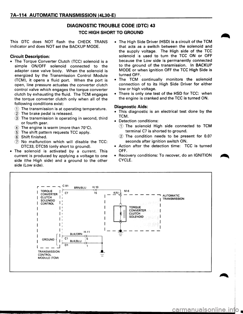
7A-114 AUTOMATIC TRANSMISSION (4l30-E)
DIAGNOSTIC TROUBLE CODE (DTC) 43
TCC HIGH SHORT TO GROUND
This DTC does NOT flash the CHECK TRANS
indicator and does NOT set the BACKUP MODE.
Circuit Description:
• The Torque Converter Clutch (TCC) solenoid is a
simple ON/OFF solenoid connected to the
adapter case
valve body. When the solenoid is
energized
by the Transmission Control Module
(TCM), it opens a fluid port. When the port is
open,
line pressure actuates the converter clutch
control valve
which engages the torque converter
clutch by exhausting the fluid. The TCM engages
the
torque converter clutch only when all of the
following conditions exist:
G) The transmission is at operating temperature.
@ The brake pedal is released.
® The transmission is operating in second, third
or fourth gear.
® The engine is warm (more than 70°C).
@ The shift pattern requests TCC apply.
® Shift finished.
(f) No malfunction which will disable the TCC:
DTC33, DTC55 (only short to ground).
• The solenoid is activated by a current. This
current is produced
by applying a voltage to one
side (the High side) and a
ground to the other
side (low side).
• The High Side Driver (HSD) is a circuit of the TCM
that acts as a switch between the solenoid and
the supply voltage. The High side of the TCC
solenoid is used to turn the TCC ON or OFF
because the Low side is permanently connected
to the ground of the transmission. In BACKUP
MODE or when ignition OFF the TCC High Side is
turned OFIF.
• The TCM continually monitors the solenoid
connection of to its High Side Driver for either
low or high voltage.
• There is only one test of the HSD for TCC: when
the engine is cranked and the TCC is turned ON.
Diagnostic .Aids:
• This diagnostic is an electrical test done by the
TCM.
• Detection conditions:
G) The solenoid High side connected to TCM
terminal C7 is shorted to ground.
@ The condition needs to be present for 0.07
seconds after ignition switch ON.
•
Action after the detection time: TCC is turned
OFF.
• Recovery eonditions: To recover, do an IGNITION
CYCLE.
r - - --, C-S1 BRN/BLU H-10 TORQUE I >-----__:_---<1 ~ ~'---------4-(A~) \1, M-6
g~~i~~TER I C7 II --1-- -- ---, AUTOMATIC
SOLENOID 1 TRANSMISSION
I
I
CONTROL
I I
I {I? GROUND I I C1 )
l---~ 01
TRANSMISSION CONTROL
MODULE (TCM)
I
: II
I
TORQUE CONVE:RTER CLUTCH
SOLEt\A0
I I H-11 - -~· - - - - - - -BLKJORN ~
9
-=-,5 BLK/BLU (
1
•
Page 988 of 1928
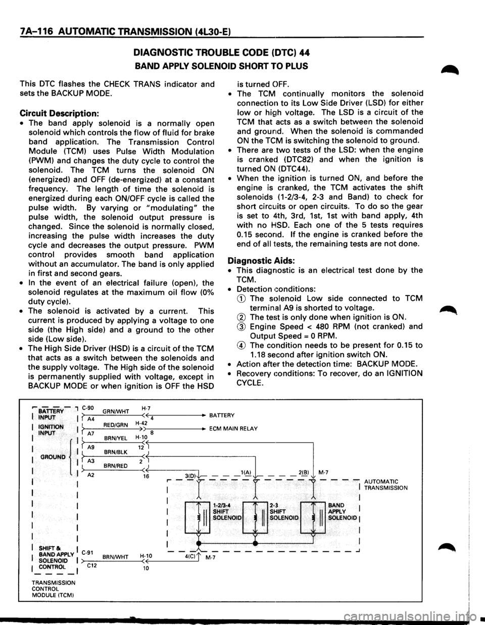
7A-116 AUTOMATIC TRANSMISSION (4L30-E)
DIAGNOSTIC TROUBLE CODE (DTC) 44
BAND APPLY SOLENOID SHORT TO PLUS
This DTC flashes the CHECK TRANS indicator and
sets the BACKUP
MODE.
Circuit Description:
• The band apply solenoid is a normally open
solenoid which controls the flow of fluid for brake
band
application. The Transmission Control
Module (TCM) uses Pulse Width Modulation
(PWM) and changes the duty cycle to control the
solenoid. The TCM turns the solenoid ON
(energized) and OFF (de-energized) at a constant
frequency. The
length of time the solenoid is
energized
during each ON/OFF cycle is called the
pulse width. By varying or "modulating" the
pulse width, the solenoid output pressure is
changed.
Since the solenoid is normally closed,
increasing the pulse width increases the duty
cycle and decreases the output pressure. PWM
control provides smooth band application
without an accumulator. The band is only applied
in first and second gears.
• In the event of an electrical failure (open), the
solenoid regulates at the maximum oil flow (0%
duty cycle).
•
The solenoid is activated by a current. This
current is produced by
applying a voltage to one
side (the High side) and a
ground to the other
side (low side).
• The High Side Driver (HSD) is a circuit of the TCM
that acts as a switch between the solenoids and
the
supply voltage. The High side of the solenoid
is permanently supplied with voltage, except in
BACKUP
MODE or when ignition is OFF the HSD
H-7
is turned OFF.
• The TCM continually monitors the solenoid
connection to its Low Side Driver (LSD) for either
low or high voltage. The LSD is a circuit of the
TCM
that acts as a switch between the solenoid
and ground. When the solenoid is commanded
ON the TCM is switching the solenoid to ground.
• There are two tests of the LSD: when the engine
is cranked (DTC82) and
when the ignition is
turned
ON (DTC44).
• When the ignition is turned ON, and before the
engine is cranked, the TCM activates the
shift
solenoids (1-2/3-4, 2-3 and Band) to check for
short circuits or open circuits. To do so the gear
is set
to 4th, 3rd, 1st, 1st with band apply, 4th
with no HSD. Each one of the 5 tests requires
0.15 second. If the engine is cranked before the
end
of all tests, the remaining tests are not done.
Diagnostic Aids:
• This diagnostic is an electrical test done by the
TCM.
• Detection conditions:
CD The solenoid Low side connected to TCM
termin.al A9 is shorted to voltage.
@ The test is only done when ignition is ON.
@ Engine Speed < 480 RPM (not cranked) and
Output
Speed = 0 RPM.
@ The condition needs to be present for 0.15 to
1.18 second after ignition switch ON.
•
Action after the detection time: BACKUP MODE.
•
Recovery conditions: To recover, do an IGNITION
CYCLE.
,... BATTERY-, C-90
I INPUT I? A4 GRN/WHT ·~-----BATTERY
( 4
I IGNITION I ? I INPUT A7 II
I { I? AS I GROUND I ? A3
I
)
I A2
I I
I
I
I I
I I
I
I
I I
I SHIFT& I
I BANDAPPLY C-91 SOLENOID I 1 _:oNTROL _ 1
TRANSMISSION
CONTROL MODULE (TCMI
C12
RED/GRN
BRN/YEL
BRN/BLK
BRN/RED
BRN/WHT
H-42 •--::------ECM MAIN RELAY )) 8 H-10
«--------3-(D--,I'l----- --'~L -,,,l M-7
( 12
2:j
16 r-- -r ----r ----
1-- --
AUTOMATIC I
I TRANSMISSION
: H::Q]:;& : I OLE SOlENOID I
I I
I I
1-213-4 2-:
-II
SHIFT
II
s SOLE NOlO s
-"--------_______ .J
H-10 ( 10
•
Page 1000 of 1928
7A-128 AUTOMATIC TRANSMISSION (4L30-E)
DIAGNOSTIC TROUBLE CODE (DTC) 55
BRAKE SWITCH SHORT TO GROUND OR OPEN
This DTC does NOT flash the CHECK TRANS
indicator and does NOT set the BACKUP MODE.
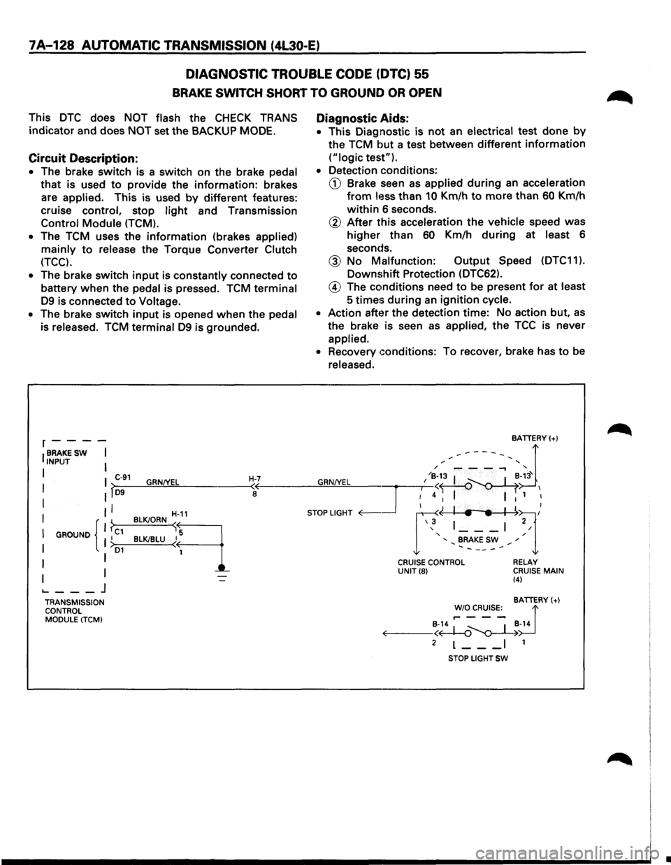
Circuit Description:
• The brake switch is a switch on the brake pedal
that is used to provide the information: brakes
are
applied. This is used by different features:
cruise control, stop
light and Transmission
Control Module (TCM).
•
The TCM uses the information (brakes applied)
mainly to release the Torque Converter Clutch
(TCC).
•
The brake switch input is constantly connected to
battery when the pedal is pressed. TCM terminal
D9 is connected to Voltage.
• The brake switch input is opened when the pedal
is released.
TCM terminal D9 is grounded.
r----
IBRAKESW I INPUT I
I I C-91 GRN/YEL H-7 I >-D9--~~~------~<
I II a
II
I GROUND I C1 I { }
I I >D1
I I
I I ._ ___ j
TRANSMISSION
CONTROL
MODULE (TCM) BLK!ORN
~-11
B~LU~q
Diagnostic
Aids:
• This Diagnostic is not an electrical test done by
the TCM but a test between different information
("logic test").
• Detection conditions:
CD Brake seen as applied during an acceleration
from less than 10 Km/h to more than 60 Km/h
within 6 seconds.
@ After this acceleration the vehicle speed was
higher than 60 Km/h during at least 6
seconds.
@ No Malfunction: Output Speed (DTC11 ).
Downshift Protection (DTC62).
@ The conditions need to be present for at least
5
times during an ignition cycle.
• Action after the detection time: No action but, as
the brake is seen as applied, the TCC is never
applied.
• Recovery conditions: To recover, brake has to be
released.
CRUISE CONTROL UNIT(8) RELAY
CRUISE MAIN (4)
BATTERY(+)
!'~~s:_ d B-14 ~ _ I _B-14 ~--<~~
2 L--_I 1
STOP LIGHT SW
•
Page 1001 of 1928
AUTOMATIC TRANSMISSION (4L30-E) 7A-129
DIAGNOSTIC TROUBLE CODE (DTC) 55
BRAKE SWITCH SHORT TO GROUND OR OPEN
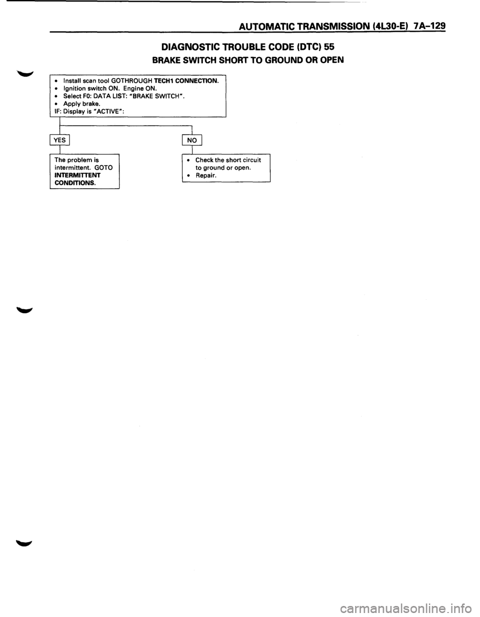
• Install scan tool GOTHROUGH TECH1 CONNECTION.
• Ignition switch ON. Engine ON.
• Select FO: DATA LIST: uBRAKE SWITCW.
•
Apply brake. IF: Display is uACTIVE":
The problem is
intermittent.
GOTO
INTERMITTENT
CONDITIONS. •
Check the short circuit to ground or open.
• Repair.