brake ISUZU TROOPER 1995 Workshop Manual
[x] Cancel search | Manufacturer: ISUZU, Model Year: 1995, Model line: TROOPER, Model: ISUZU TROOPER 1995Pages: 1928
Page 1002 of 1928
7A-130 AUTOMATIC TRANSMISSION (4l30-E)
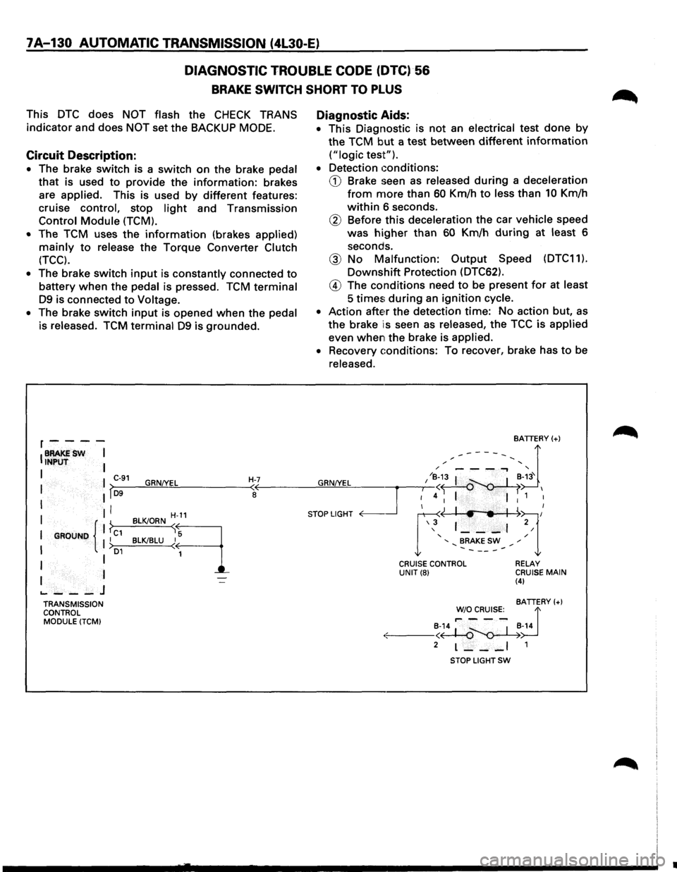
DIAGNOSTIC
TROUBLE CODE (DTC)·56
BRAKE SWITCH SHORT TO PLUS
This DTC does NOT flash the CHECK TRANS
indicator and does
NOT set the BACKUP MODE.
Circuit Description:
• The brake switch is a switch on the brake pedal
that is used to provide the information: brakes
are
applied. This is used by different features:
cruise
control, stop light and Transmission
Control Module (TCM).
•
The TCM uses the information (brakes applied)
mainly to release the Torque Converter Clutch
(TCC).
• The brake switch input is constantly connected to
battery when the pedal is pressed. TCM terminal
D9 is connected to Voltage.
•
The brake switch input is opened when the pedal
is released. TCM terminal D9 is grounded.
r----
IBRAKESW I INPUT I
I I C-91 GRN!YEL H-7 I lf~D-9--~~~------~~
I II I
I GROUND { 1 ?c1 II I >o1
I I
I I
.._ ___ J
TRANSMISSION
CONTROL
MODULE (TCM)
H-11
BLK!ORN sq
BLK!BLU ~
1
Diagnostic Aids:
• This Diagnostic is not an electrical test done by
the TCM but a test between different information
("logic test").
•
Detection conditions:
CD Brake seen as released during a deceleration
from more than 60 Km/h to less than 10 Km/h
within 6 seconds.
® Before this deceleration the car vehicle speed
was
higher than 60 Km/h during at least 6
seconds.
@ No Malfunction: Output Speed (DTC11).
Downshift Protection (DTC62).
@ The conditions need to be present for at least
5 times; during an ignition cycle.
•
Action atte~r the detection time: No action but, as
the brake is seen as released, the TCC is applied
even when the brake is applied.
•
Recovery conditions: To recover, brake has to be
released.
BATTERY(+)
,.------, d / '
GRN/YEL I /~;3 I ~-~3' I
~4 I I 1 I
STOP LIGHT <0---.Jr ~~l/ \3 1 ___ , 2/
' / ' BRAKE SW ,. .......... -----.......
CRUISE CONTROL UNIT(8) RELAY CRUISE MAIN (4)
BATTERY(+)
~~~R~s:_ d
·:.:-: ---~~~-14
2 L--_I 1
STOP LIGHT SW
•
Page 1003 of 1928
AUTOMATIC TRANSMISSION (4L30-E) 7A-131
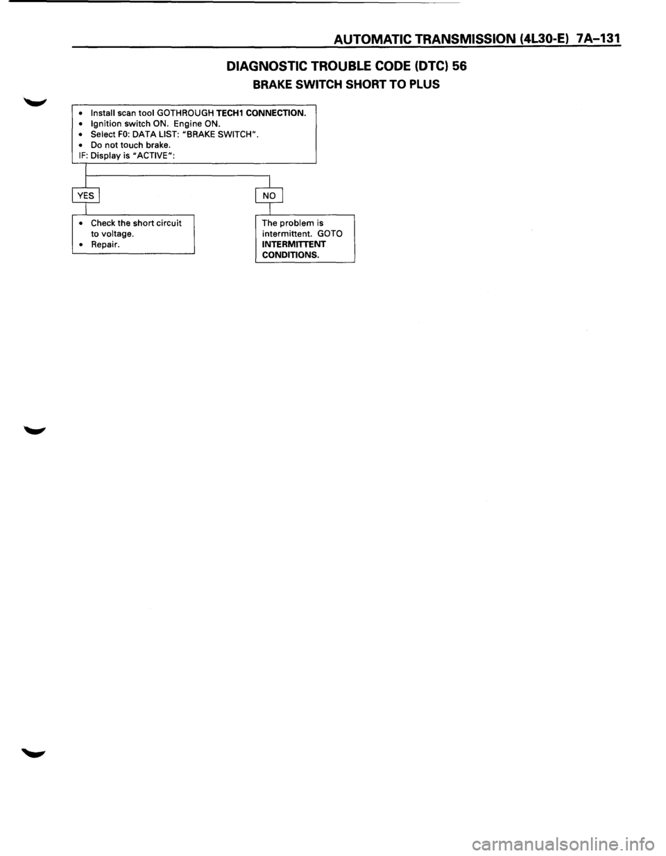
DIAGNOSTIC TROUBLE CODE (DTC) 56
BRAKE SWITCH SHORT TO PLUS
• Install scan tool GOTH ROUGH TECH1 CONNECTION.
• Ignition switch ON. Engine ON.
• Select FO: DATA LIST: uBRAKE SWITCH".
•
Do not touch brake. IF: Display is uACTIVEu:
•
Check the short circuit
to voltage.
•
Repair. The
problem is
intermittent. GOTO
INTERMITTENT CONDITIONS.
Page 1016 of 1928
7A-144 AUTOMATIC TRANSMISSION (4L30-E)
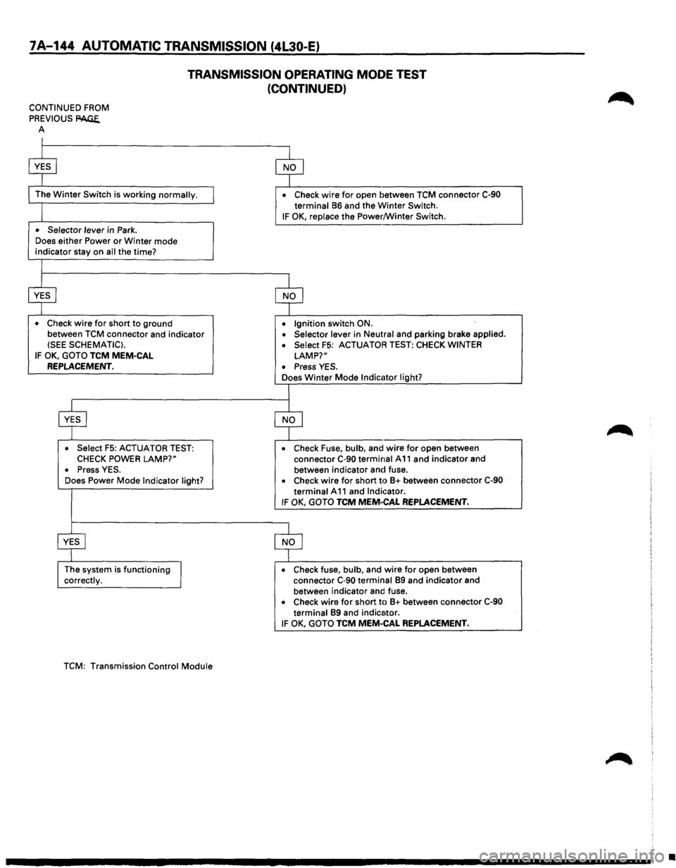
TRANSMISSION OPERATING MODE TEST
(CONTINUED)
CONTINUED FROM
PREVIOUS
PAGE. A
I
$
The Winter Switch is working normally.
I
• Selector lever in Park .
Does
either Power or Winter mode indicator stay on all the time?
I
$
• Check wire for short to ground
between
TCM connector and indicator (SEE SCHEMATIC).
IF OK, GOTO TCM MEM-CAL REPLACEMENT.
$
• Select F5: ACTUATOR TEST: CHECK POWER LAMP?"
• Press YES .
Does Power Mode Indicator light?
~
The system is functioning
J correctly.
TCM:
Transmission Control Module
$
• Check wire for open between TCM connector C-90 terminal 86 and the Winter Switch.
IF OK, replace the Power/Winter Switch.
$
• Ignition switch ON .
• Selector lever in Neutral and parking brake applied .
• Select F5: ACTUATOR TEST: CHECK WINTER
LAMP?"
• Press YES .
Does Winter Mode Indicator light?
I
$
• Check Fuse, bulb, and wire for open between
connector C-90 terminal A 11 and indicator and
between indicator and fuse.
• Check wire for short til 8+ between connector C-90
terminal A 11 and Indicator. IF OK, GOTO TCM MEM-CAL REPLACEMENT.
$
• Check fuse, bulb, and wire for open between
connector C-90 terminal 89 and indicator and
between indicator andl fuse.
• Check wire for short to 8+ between connector C-90 terminal 89 and indicator.
IF OK, GOTO TCM MEM-CAL REPLACEMENT.
•
Page 1022 of 1928
7A-150 AUTOMATIC TRANSMISSION (4L30-E)
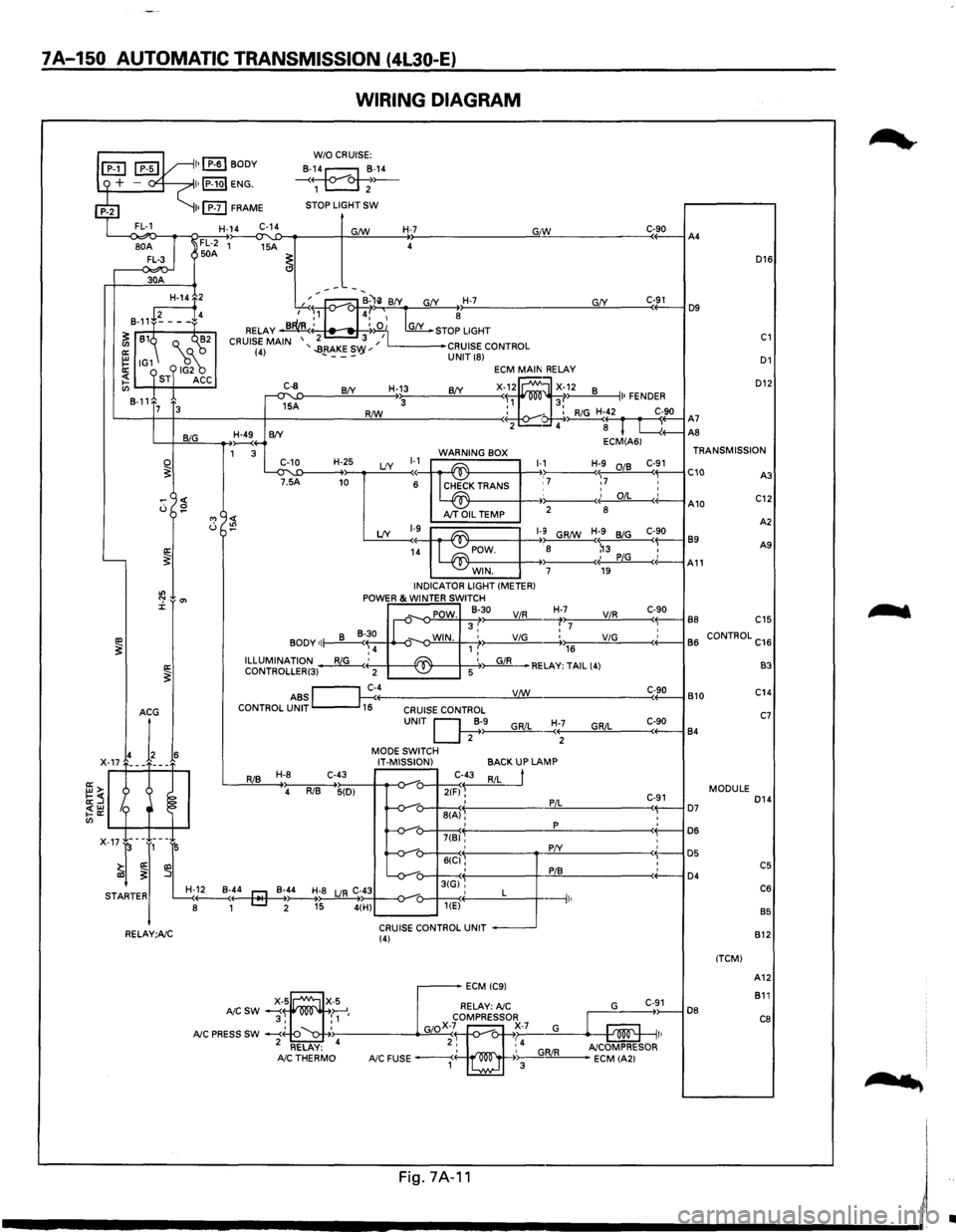
WIRING DIAGRAM
L--<~o-~~~~~~--~~~----~~~----~~--------------~G"IW~------------C«-9_0--iA4
D16
30A
D12
GfY ---~:at--B-'li BfY G(Y H-7 ,...-..~., 4,' ~ ~
RELAY ~' ~:iO 1 [my_ STOP LIGHT
2 3 I CRUISE MAIN '..BRAKES '' L------•CRUISE CONTROL (4) - ---vy UNIT (8) D1
~2
8-11+~---f4
~ 81~ Q._ ("'~2
~ IG1 18~ ~ ST ACC en 8-11
C-91 D9
C1
ECM MAIN RELAY
X-f~ ~X~~2 8 II• FENDER R/W : - : RiG H-42 C-90 '-----t--t------+-------!:!Lll----------< • ~( r fl A7 2 4 8 L....{+--AS
C-8
~A
H-13 BfY BfY 3 7 3
L-+-JB~~I,_IG __ __....,~4-B(Y ECM(A61 1 3 WARNING BOX TRANSMISSION
~T'~5'-'1:D----H-+~2~5 LfY ~~~ ~K TRANS 1-,17 Hr7 :~ C-~1 C10 C::
0 ~
"' <( u :!?
'----~
"' ":' 0'> J:
IXl ~ a: ~
I~ A10 AJT OIL TEMP 2
8
A
2
LfY 1-9~ ~1-9 GR/W H;9 BiG C-90 89 1~ POW. : 8 ~3 , A9
- -~· PiG c(-A11 WIN. 7 19 INDICATOR LIGHT (METER) POWER & WINTER SWITCH
_,. POW. 8-30 ViR H-,>,7:;-----'V"-'iR.!..,_ ___ c<-~9-0-l B8 C15 II-v 3, :7 • BODY of~~ ~-o-WIN. 1 ,' ViG -----.+.,.,176 __ ____;;V.:..;iG=-----<+'-----1 B
6 CONTROL C16 ,4 ILLUMINATION~' ~ '~RELAY: TAIL (4) CONTROLLER(3) 2 -~ 5
ABS ~c~4----------------__yV:J..:!:!._/W ______________ ___:C<-~9:..::0-l B 10 CONTROL UNIT 16 CRUISE CONTROL
RiB H-8 C-43
4 RiB 5(D)
UNIT Q;·>-9------"G,_,Ri_,L_~:+--;-----'G""R""iL::,_ ___ c,-+-9-0----j 84
MODE SWITCH
IT-MISSION)
C-43
2(F) ~ ' 8(A), '
BACKUP LAMP
RiL
t
PiL
p
C-91 ( D7 : D6
B3
C14
C7
MODULE D14
: D5 : C5 ( D4 C6
B5
7(B)'
X-17-l-~J,-~L -v-: 6((:1§': :
r! -v-u-3tGi'', STARTER H-~..._:4---4r::J-Mo~-_B~;~;8 LJR C;~434--o-_,_-o---+---<·' L ---1 8 1 [::::J 2 15 4(H) u---~< 1 '
CRUISE CONTROL UNIT RELAY;A/C (4)
DB
(TCM) 812
A12
811
C8
....
'
Fig.7A·11 I
------------------------~~
•
Page 1024 of 1928
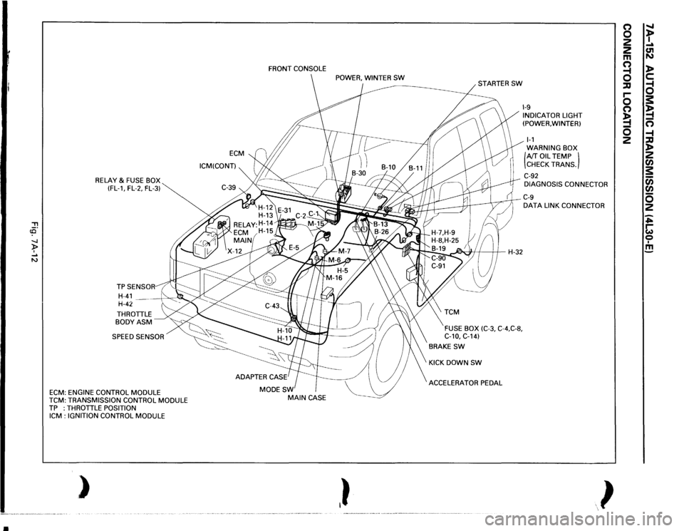
•
, cCi" -.J )> I .... N
RELAY
& FUSE BOX
(FL-1, FL-2, FL-3)
THROTTLE BODYASM SPEED SENSOR
ECM:
ENGINE CONTROL
MODULE
TCM:
TRANSMISSION CONTROL
MODULE
TP :THROTTLE
POSITION
ICM
: IGNITION CONTROL
MODULE
)
ECM
ICM(CONT) FRONT
CONSOLE
MODESW
MAIN
CASE
,}
~H-32
FUSE BOX
(C-3,
C-4,C-8,
C-10,
C-14)
BRAKE
SW
KICK DOWN
SW
ACCELERATOR PEDAL
1-9 INDICATOR LIGHT
(POWER, WINTER) 1-1 WARNING BOX (AfT
OIL
TEMP )
CHECK TRANS.
C-92 DIAGNOSIS CONNECTOR C-9 DATA
LINK CONNECTOR
}
(') 0 2
2 m a ::IJ r-0 (') !4 0 2
" t .... C1l N l> c: a s: !4 n -4 ::IJ l> 2 rA s: c;; rA 0 2 ~ ~ 0 I m
Page 1027 of 1928
... ......,.
AUTOMATIC TRANSMISSION (4L30-E) 7A-155
ON-VEHICLE SERVICE
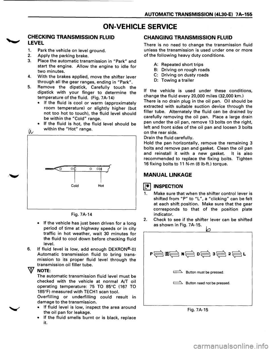
CHECKING TRANSMISSION FLUID
LEVEL
1. Park the vehicle on level ground.
2. Apply the parking brake.
3. Place the automatic transmission in "Park" and
start the engine.
Allow the engine to idle for
two minutes.
4. With the brakes applied, move the shifter lever
through all the gear ranges, ending in "Park".
5. Remove the dipstick, Carefully touch the
dipstick with your finger to determine the
temperature of the fluid. (Fig. 7A-14)
• If the fluid is cool or warm (approximately
room temperature) or slightly higher (but
not too hot to touch), the fluid level should
be within the "Cold" range.
• If the fluid is hot, the fluid level should be
(A; within the "Hot" range.
6.
Cold Hot
Fig. 7A-14
• If the vehicle has just been driven for a long
period of time at highway speeds or in city
traffic in hot weather, wait 30 minutes for
the fluid to cool down before checking fluid
level.
If fluid level is low, add enough DEXRON®-m
Automatic transmission fluid to bring trans
mission
to its proper fluid level through the
transmission oil filler tube.
NOTE:
The automatic transmission fluid level must be
checked
with the vehicle at normal AfT oil
operating temperature: 75 TO 85°C (167 TO
185°F)
measured with TECH1 scan tool.
Overfilling or underfilling could result in
damage
to the transmission.
• If fluid level is low, inspect the area around
the oil pan for leakage.
•
If the fluid smells burnt or is black, replace
it.
CHANGING TRANSMISSION FLUID
There is no need to change the transmission fluid
unless the transmission is used under one or more
of the following heavy duty conditions.
A: Repeated
short trips
B: Driving on rough roads
C: Driving on dusty roads
D: Towing a trailer
If the vehicle is used under these conditions,
change the fluid every 20,000 miles (32,000 km.)
There is
no drain plug in the oil pan. Oil should be
extracted
with suitable suction device through the
filler tube. Alternately the fluid can be drained by
carefully removing the oil pan. Place a large drain
pan
under the oil pan, remove 13 bolts on the right,
left and front sides of the oil pan and loosen 3 bolts
on the rear side.
Drain
the fluid carefully.
Hold
the pan horizontally, remove the remaining 3
bolts and remove pan and gasket. Clean the oil pan
and
reinstall it . with a new gasket. It is also
recommended to replace the fixing bolts. Tighten
16 fixing bolts to 11 N·m (8 lb·ft.) torque.
MANUAL LINKAGE
~ INSPECTION
1. Make sure that when the shifter control lever is
shifted
from "P" to "L", a "clicking" can be felt
at each shift position. Make sure that the gear
corresponds
to that of the position plate
indicator.
2. Check to see if the shifter lever can be shifted
as
shown in Fig. 7A-15. jQ
~ Button must be pressed.
~ Button need not be pressed.
Fig. 7A-15
Page 1029 of 1928
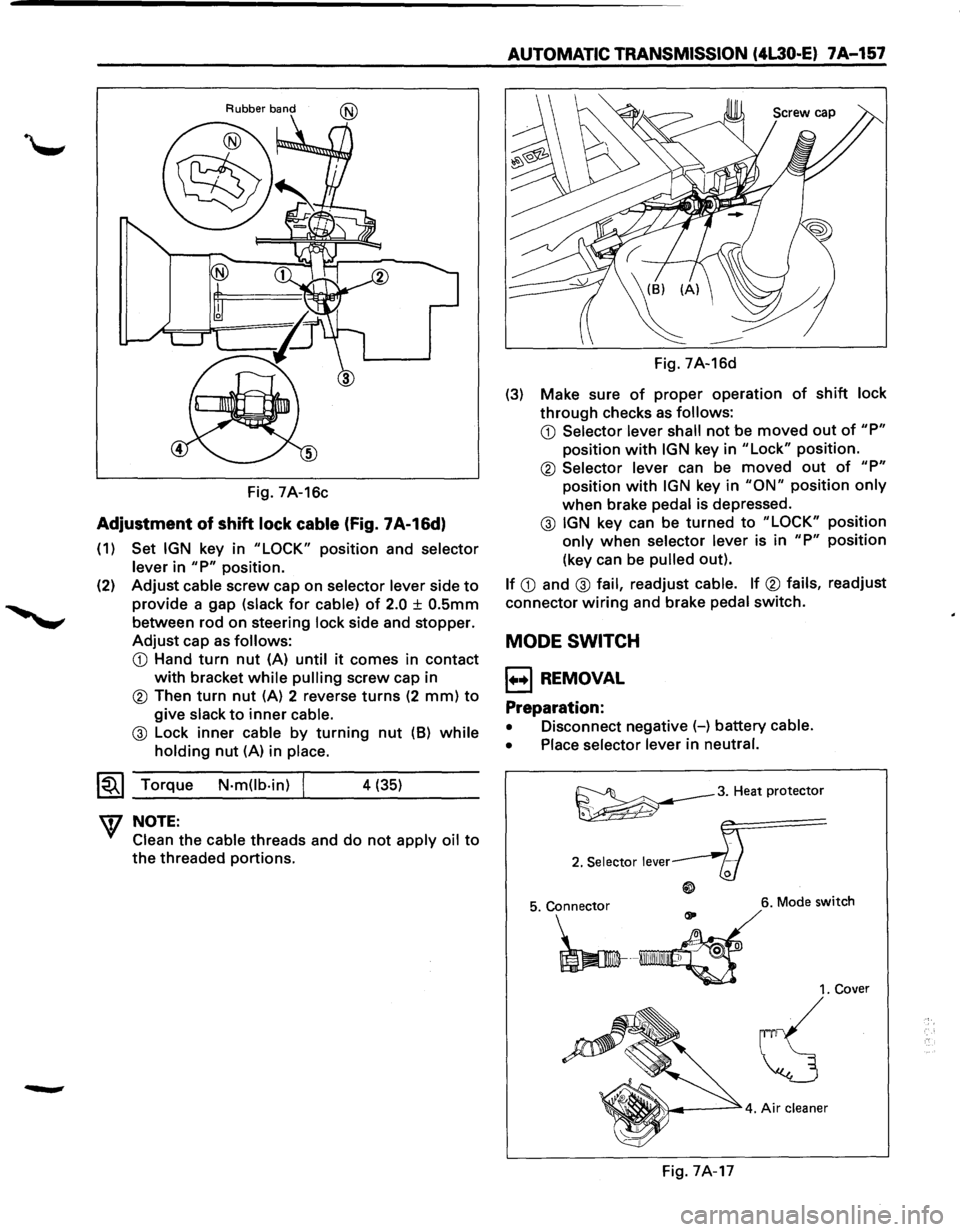
Rubber band
Fig. 7A-16c
Adjustment of shift lock cable (Fig. 7A-16d)
(1) Set IGN key in "LOCK" position and selector
lever
in "P" position.
(2)
Adjust cable screw cap on selector lever side to
provide a gap (slack for cable) of 2.0 ± O.Smm
between rod on steering lock side and stopper.
Adjust cap as follows:
CD Hand turn nut (A) until it comes in contact
with bracket while pulling screw cap in
® Then turn nut (A) 2 reverse turns (2 mm) to
give slack to inner cable.
@ Lock inner cable by turning nut (8) while
holding nut (A) in place.
~~~ Torque N-m(lb-in) j 4 (35)
W NOTE:
Clean the cable threads and do not apply oil to
the threaded portions.
AUTOMATIC TRANSMISSION (4L30·E) 7A-157
Fig. 7A-16d
(3) Make sure of proper operation of shift lock
through checks as follows:
CD Selector lever shall not be moved out of "P"
position with IGN key in "Lock" position.
® Selector lever can be moved out of "P"
position with IGN key in "ON" position only
when brake pedal is depressed.
@ IGN key can be turned to "LOCK" position
only when selector lever is in "P" position
(key can be
pulled out).
If CD and @ fail, readjust cable. If ® fails, readjust
connector
wiring and brake pedal switch.
MODE SWITCH
1++1 REMOVAL
Preparation:
• Disconnect negative (-) battery cable.
• Place selector lever
in neutral.
~3. Heat protector
2. Selector lever
6. Mode switch
1. Cover
~
Fig. 7A-17
Page 1046 of 1928
7A-174 AUTOMATIC TRANSMISSION (4L30·E)
1•!•1 biSASSEMBLV
During the disassembly and reassembly of the
following components, perform the following:
• Wash each part thoroughly and blow air
through each oil passage and groove to
eliminate blockage.
• Seal rings, roll pins and gaskets should be
replaced
with new parts.
• When assembling the components, apply
DEXRON®-m Automatic Transmission Fluid
(ATF)
to each seal, rotating part and sliding
part.
• Do not dip those parts having a facing, such as
drive plate for clutch or brake, in the cleaner
when washing it with solvent.
Also, always wash
it with new ATF two or
three times after cleaning with solvent.
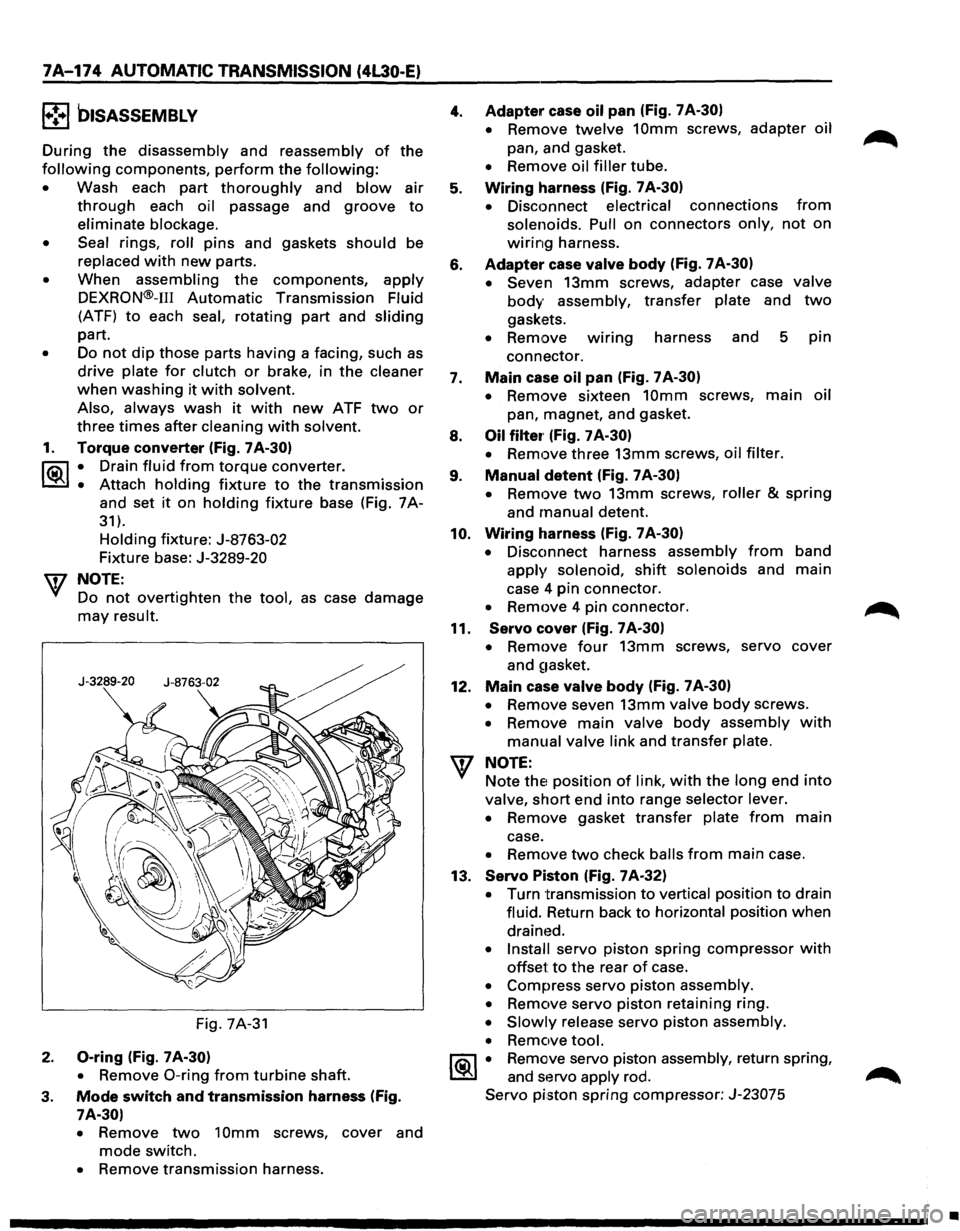
1. Torque converter (Fig. 7A-30)
l"i:\1 • Drain fluid from torque converter.
~ • Attach holding fixture to the transmission
and set it on holding fixture base (Fig. 7A-
31).
Holding fixture: J-8763-02
Fixture base: J-3289-20
w NOTE:
Do
not overtighten the tool, as case damage
may result.
Fig. 7A-31
2. 0-ring (Fig. 7 A-30)
•
Remove 0-ring from turbine shaft.
3. Mode switch and transmission harness (Fig.
7A-30)
•
Remove two 10mm screws, cover and
mode switch.
• Remove transmission harness.
4.
5.
6.
7.
8.
9.
10.
11.
12.
Adapter case oil pan (Fig. 7 A-30)
•
Remove twelve 10mm screws, adapter oil
pan, and gasket.
• Remove oil filler tube.
Wiring harness (Fig. 7 A-30)
•
Disconnect electrical connections from
solenoids. Pull on connectors only, not on
wiring harness.
Adapter case valve body (Fig. 7A-30)
• Seven
13mm screws, adapter case valve
body assembly, transfer plate and two
gaskets.
• Remove wmng harness and 5 pin
connector.
Main case oil pan (Fig. 7 A-30)
•
Remove sixteen 10mm screws, main oil
pan, magnet, and gasket.
Oil filter· (Fig. 7 A-30)
•
Remove three 13mm screws, oil filter.
Manual detent (Fig. 7 A-30)
•
Remove two 13mm screws, roller & spring
and manual detent.
Wiring harness (Fig. 7 A-30)
•
Disconnect harness assembly from band
apply solenoid, shift solenoids and main
case 4 pin connector.
• Remove 4 pin connector.
Servo cover (Fig. 7 A-30)
•
Remove four 13mm screws, servo cover
and
~1asket.
Main case valve body (Fig. 7 A-30)
•
Remove seven 13mm valve body screws.
• Remove main valve body assembly with
manual valve link and transfer plate.
NOTE: Note
thE! position of link, with the long end into
valve, short end into range selector lever.
• Remove gasket transfer plate from main
case.
• Remove two check balls from main case.
13.
Servo Piston (Fig. 7A-32)
• Turn transmission to vertical position to drain
fluid. Return back
to horizontal position when
drained.
• Install servo piston spring compressor with
offset to the rear of case.
• Compress servo piston assembly.
• Remove servo piston retaining ring.
• Slowly release servo piston assembly.
• Remove tool.
1®.1 • Remove servo piston assembly, return spring,
and servo apply rod.
Servo piston spring compressor: J-23075
•
Page 1048 of 1928
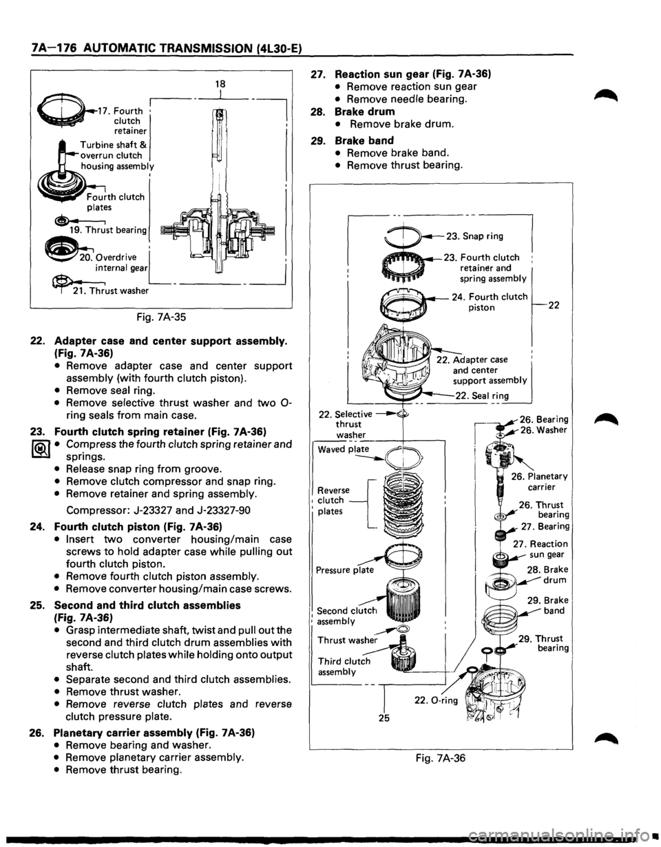
7A-176 AUTOMATIC TRANSMISSION (4l30-E)
~-17. Fourth •
~ clutch retainer
Turbine shaft
& overrun clutch
housing assembly I
Fig. 7A-35
18
22. Adapter case and center support assembly.
(Fig. 7 A-36)
• Remove adapter case and center support
assembly (with fourth clutch piston).
• Remove seal ring.
• Remove selective thrust washer and two 0-
ring seals from main case.
23. Fourth clutch spring retainer (Fig. 7A-36)
~ • Cor:npress the fourth clutch spring retainer and
spnngs.
• Release snap ring from groove.
• Remove clutch compressor and snap ring.
• Remove retainer and spring assembly.
Compressor: J-23327 and J-23327-90
24. Fourth clutch piston (Fig. 7A-36)
• Insert two converter housing/main case
screws to
hold adapter case while pulling out
fourth clutch piston.
• Remove fourth clutch piston assembly.
•
Remove converter housing/main case screws.
25. Second and third clutch assemblies
(Fig. 7A-36)
• Grasp intermediate shaft, twist and pull out the
second and third
clutch drum assemblies with
reverse
clutch plates while holding onto output
shaft.
• Separate second and third clutch assemblies.
•
Remove thrust washer.
• Remove reverse clutch plates and reverse
clutch pressure plate.
26. Planetary carrier assembly (Fig. 7A-36)
• Remove bearing and washer.
• Remove planetary carrier assembly.
•
Remove thrust bearing.
27. Reaction sun gear (Fig. 7A-36)
• Remove reaction sun gear
• Remove needle bearing.
28. Brake drum
• Remove brake drum.
29. Brake band
• Remove brake band.
• Remove thrust bearing.
,-ii--23.~:.~
I 23. Fou_rth clutch :
1 reta~ner and
' spring
assembly
Reverse'-[. 1 clutch
' plates
~~~~ ..... -24. Fourth clutch piston 22
. 27. Re:~~~rn
Second
clutch : assembly
~
Thrustwa~~
Third clutch ._
assembly -
25
Fig. 7A-36
Brake drum
. 29. Brake
band
•
Page 1049 of 1928
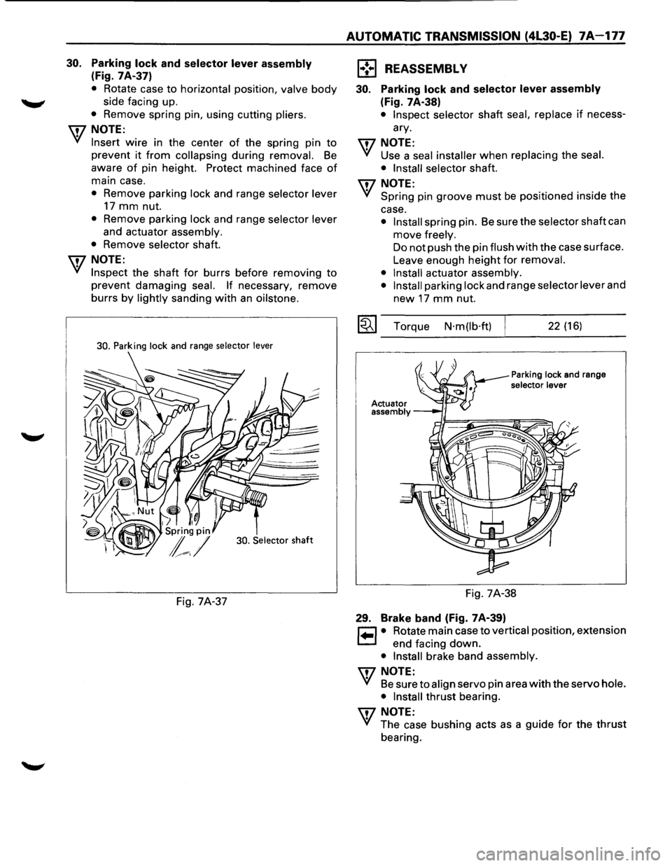
30. Parking lock and selector lever assembly
(Fig. 7A-37)
• Rotate case to horizontal position, valve body
side facing up.
• Remove spring pin, using cutting pliers.
\fl NOTE:
~ Insert wire in the center of the spring pin to
prevent it from collapsing during removal. Be
aware of pin height. Protect machined face of
main case.
• Remove parking lock and range selector lever
17 mm nut.
• Remove parking lock and range selector lever
and actuator assembly.
•
Remove selector shaft.
\fl NOTE:
~ Inspect the shaft for burrs before removing to
prevent damaging seal. If necessary, remove
burrs
by lightly sanding with an oilstone.
30. Parking lock and range selector lever
30. Selector
shaft
Fig. 7A-37
AUTOMATIC TRANSMISSION (4L30-E) 7A-177
1 .. ! .. 1 REASSEMBLY
30. Parking lock and selector lever assembly
(Fig. 7A-38)
• Inspect selector shaft seal, replace if necess
ary.
\fl NOTE:
~ Use a seal installer when replacing the seal.
• Install selector
shaft.
\fl NOTE:
~ Spring pin groove must be positioned inside the
case.
• Install spring pin. Be sure the selector shaft can
move
freely.
Do not push the pin flush with the case surface.
Leave enough
height for removal.
• Install
actuator assembly.
• Install
parking lock and range selector lever and
new 17 mm nut.
~~~ Torque N·m(lb·ft) 22 (16)
Parking lock and range selector lever
Fig. 7A-38
29. Brake band (Fig. 7A-39)
~ • Rotate main case to vertical position, extension
~ end facing down.
• Install brake band assembly.
\fl NOTE:
~ Be sure to align servo pin area with the servo hole.
• Install
thrust bearing.
\fl NOTE:
~ The case bushing acts as a guide for the thrust
bearing.