brake ISUZU TROOPER 1995 Workshop Manual
[x] Cancel search | Manufacturer: ISUZU, Model Year: 1995, Model line: TROOPER, Model: ISUZU TROOPER 1995Pages: 1928
Page 498 of 1928
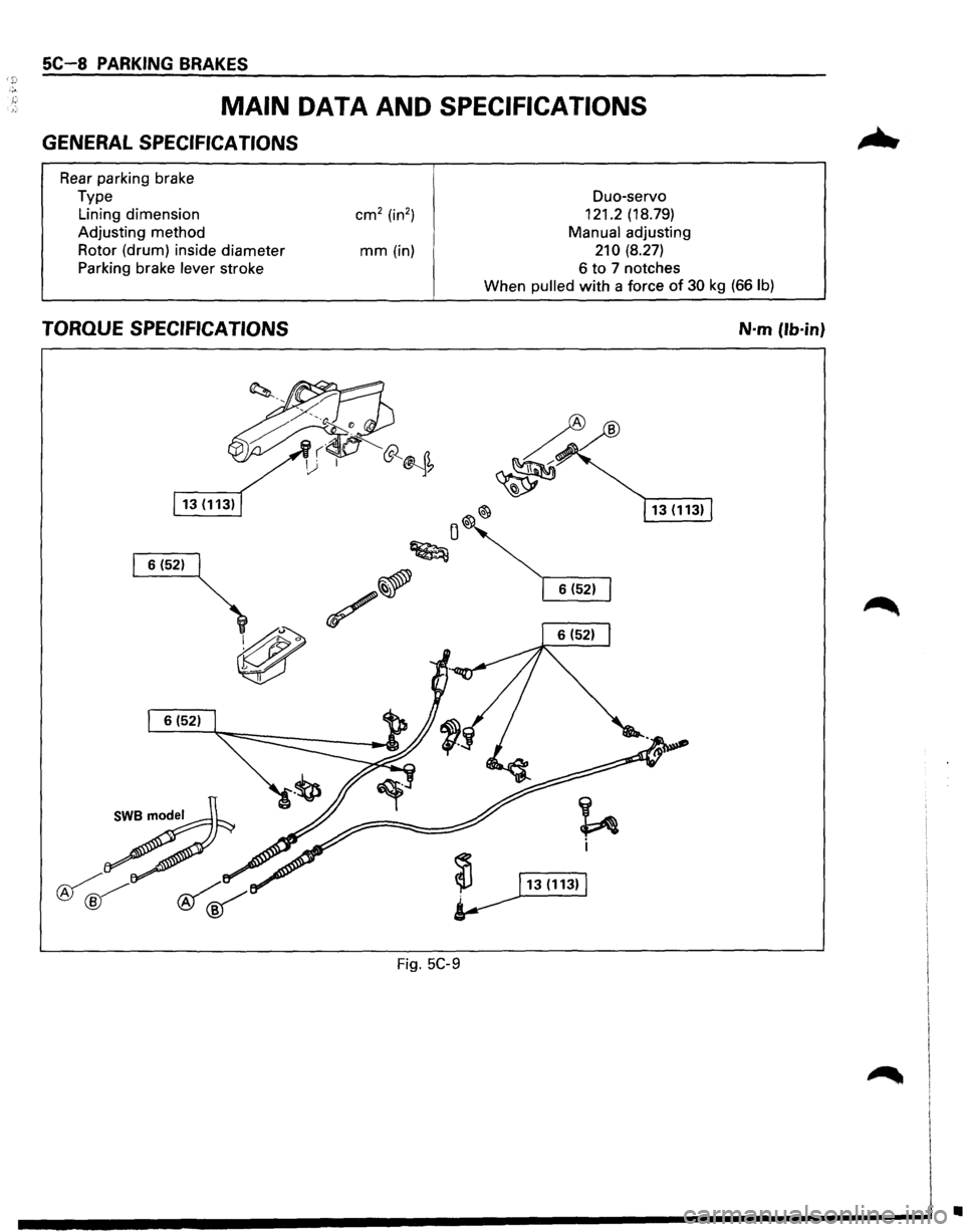
SC-8 PARKING BRAKES
MAIN DATA AND SPECIFICATIONS
GENERAL SPECIFICATIONS
Rear parking brake
Type Lining dimension
Adjusting method
Rotor (drum) inside diameter
Parking brake
lever stroke
mm (in) Duo-servo
121.2
(18.79)
Manual adjusting
210 (8.27)
6 to 7 notches
When pulled
with a force of 30 kg (66 lb)
TORQUE SPECIFICATIONS N·m (lb·in}
Fig. 5C-9
•
Page 507 of 1928
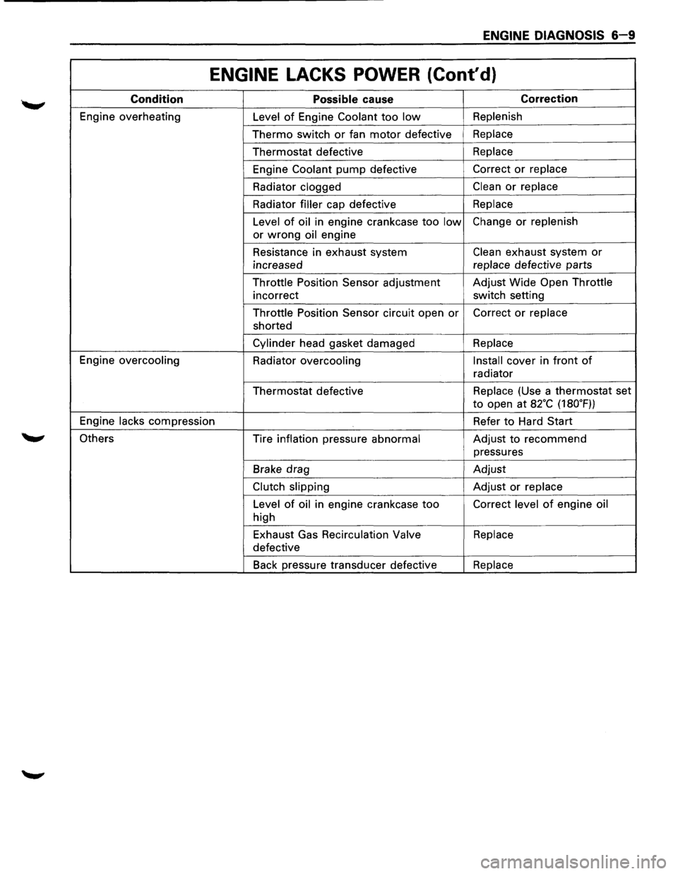
ENGINE DIAGNOSIS 6-9
ENGINE LACKS POWER (Cont'd)
Condition Possible cause Correction
Engine overheating
Level of Engine Coolant too low Replenish
Thermo switch or fan motor defective Replace
Thermostat defective Replace
Engine
Coolant pump defective Correct or replace
Radiator clogged
Clean or replace
Radiator
filler cap defective Replace
Level
of oil in engine crankcase too low Change or replenish
or
wrong oil engine
Resistance in exhaust system
Clean exhaust system or
increased replace
defective parts
Throttle Position Sensor adjustment Adjust
Wide Open Throttle
incorrect switch setting
Throttle Position Sensor circuit open
or Correct or replace
shorted
Cylinder head gasket damaged Replace
Engine overcooling
Radiator
overcooling Install cover
in front of
radiator
Thermostat defective Replace
(Use a thermostat set
to open at a2·c (180.F))
Engine
lacks compression Refer to Hard Start
Others Tire inflation pressure
abnormal Adjust to recommend
pressures
Brake drag Adjust
Clutch slipping Adjust or replace
Level
of oil in engine crankcase too Correct level of engine oil
high
Exhaust Gas
Recirculation Valve Replace
defective
Back pressure transducer defective
Replace
Page 512 of 1928
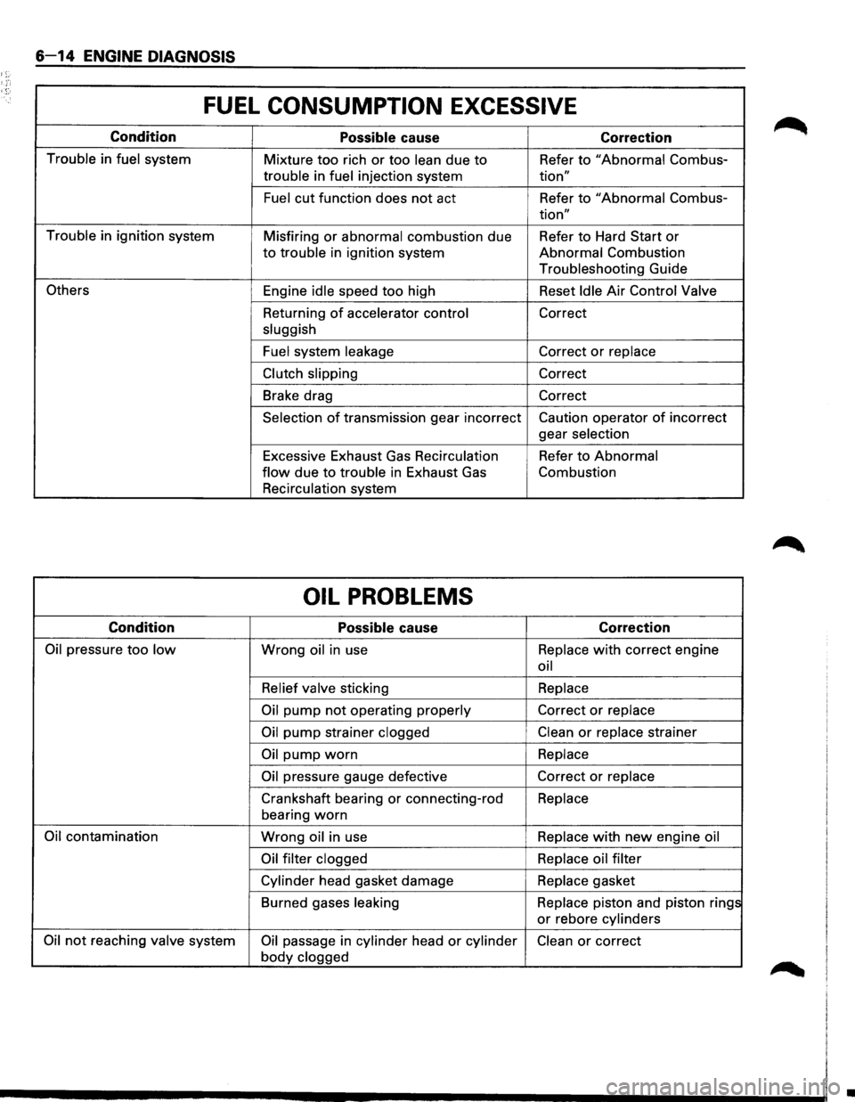
6-14 ENGINE DIAGNOSIS
1;:-
FUEL CONSUMPTION EXCESSIVE
Condition
Possible cause Correction
Trouble in fuel system
Mixture too rich or too lean due to Refer to "Abnormal Combus-
trouble in fuel injection system tion"
Fuel cut function does not act Refer to "Abnormal Combus-
tion"
Trouble in ignition system
Misfiring or abnormal combustion due Refer to Hard Start or
to trouble in ignition system Abnormal Combustion
Troubleshooting Guide
Others Engine idle speed too high Reset Idle Air Control Valve
Returning
of accelerator control Correct
sluggish
Fuel system leakage
Correct or replace
Clutch slipping Correct
Brake drag Correct
Selection of transmission gear incorrect Caution operator of incorrect
gear selection
Excessive Exhaust
Gas Recirculation Refer to Abnormal
flow due to trouble in Exhaust Gas Combustion
Recirculation system
OIL PROBLEMS
Condition
Possible cause Correction
Oil pressure too low Wrong oil in use Replace with correct
engine
oil
Relief valve sticking Replace
Oil pump not operating
properly Correct or replace
Oil pump strainer clogged Clean or replace strainer
Oil pump worn Replace
Oil pressure gauge defective Correct or replace
Crankshaft bearing or connecting-rod Replace
bearing
worn
Oil contamination Wrong oil in use Replace with new engine
oil
Oil filter clogged Replace oil filter
Cylinder head gasket damage Replace
gasket
Burned gases leaking Replace piston and piston rings
or rebore cylinders
Oil not reaching valve system Oil passage in cylinder head or cylinder Clean or correct
body clogged
•
Page 632 of 1928
68 - 4 ENGINE COOLING
ON-VEHICLE SERVICE
DRAINING AND REFILLING COOLING
SYSTEM
Before draining the cooling system, inspect the sys
tem and perform any necessary service to ensure that
it is clean, does not leak and is in proper working
order. The Engine Coolant (EC) level should be be
tween the "MIN" and "MAX" lines of reserve tank
when the engine is cold. If low, check for leakage and
add
EC up to the "MAX" line. There should not be any
excessive deposit of rust or scales around the radiator
cap
or radiator filler hole, and the EC should also be
free
from oil. Replace the EC if excessively dirty.
1. Completely drain the cooling system by opening
the drain petcock at the bottom of the radiator.
2. Remove the radiator cap.
W WARNING
To avoid the danger of being burned, do not
remove the cap while the engine and radiator
are still hot. Scalding fluid and steam can be
blown out under pressure.
3. Disconnect all hoses from the EC reserve tank.
Scrub and clean the inside of the reserve tank with
soap and water. Flush it well with clean water,
then drain it. Install the reserve tank and hoses.
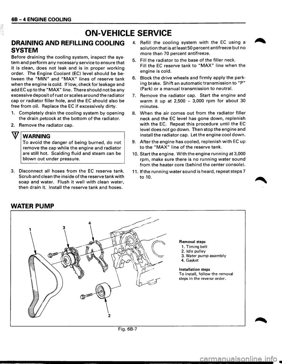
WATER PUMP
3
j
2
4. Refill the cooling system with the EC using a
solution that is at least 50 percent antifreeze but no
more than 70 percent antifreeze.
5. Fill the radiator to the base of the filler neck.
Fill the EC reserve tank to "MAX" line when the
engine is cold.
6. Block the drive wheels and firmly apply the park
ing brake.
Shift an automatic transmission to "P"
(Park) or a manual transmission to neutral.
7. Remove the radiator cap. Start the engine and
warm it up at 2,500 -3,000 rpm for about 30
minutes.
8. When the air comes out from the radiator filler
neck and the EC level has gone down, replenish
with the EC. Repeat this procedure until the EC
level does not go down. Then stop the engine and
install the radiator cap. Let the engine cool down.
9. After the engine has cooled, replenish with EC up
to the "MAX" line of the reserve tank.
10. Start the engine. With the engine running at 3,000
rpm, make sure there is no running water sound
from the heater core (behind the center console).
11. If the running water sound is heard, repeat steps 7
to 10.
Removal steps
1. Timing
belt 2. Idle pulley 3. Water pump assembly
4. Gasket
Installation steps To install, follow the removal steps in the reverse order.
Fig. 6B-7
•
Page 657 of 1928
ENGINE ELECTRICAL 601-3
ON-VEHICLE SERVICE
BATTERY CHARGING
Observe the following safety precautions when
charging the battery:
1. Never attempt to charge the battery when the
fluid level is below the lower level line on the
side
of the battery. In this case, the battery
must be replaced.
2. Pay close attention to the battery during the
charging procedure.
Battery charging
should be discontinued or the
rate
of charge reduced if the battery feels hot
to the touch.
Battery charging
should be discontinued or the
rate
of charge reduced if the battery begins to
gas or spew electrolyte from the vent holes.
3. In order to more easily view the hydrometer
blue dot or ring, it may be necessary to jiggle
or tilt the battery.
4. Battery temperature can have a great effect on
battery charging capacity.
5. The sealed battery used on this vehicle may be
either quick-charged or slow-charged in the
same manner
as other batteries.
Whichever method you decide
to use, be sure
that you
completely charge the battery. Never
partially charge the battery.
JUMP STARTING
JUMP STARTING WITH AN AUXILIARY
(BOOSTER)
BATTERY
W CAUTION:
Never push or tow the vehicle in an attempt to
start it.
Serious damage to the emission sys
tem as
well as other vehicle parts will result.
Treat both the discharged battery and the
booster battery
with great care when using
jumper cables. Carefully follow the jump start
ing procedure, being
careful at all times to
avoid sparking.
wwARNING:
Failure to carefully follow the jump starting
procedure
could result in the following:
1. Serious personal injury, particulaly to your
eyes.
2. Property damage from a battery explo
sion, battery acid, or an electrical fire.
3. Damage to the electronic components of
one or both vehicles particularly.
Never expose the battery to an open flame or elec
trical
spark. Gas generated by the battery may catch
fire
or explode.
Remove any rings, watches, or other jewelry before
working around the battery. Protect
your eyes by
wearing
an approved set of goggles.
Never allow battery fluid to come in contact with
your eyes or skin.
Never
allow battery fluid to come in contact with
fabrics or painted surfaces.
Battery
fluid is a highly corrosive acid.
Should battery fluid come in contact with your eyes,
skin, fabric, or a painted surface,
immediately and
thoroughly rinse the affected area with clean tap
water. Never
allow metal tools or jumper cables to come
in contact with the positive battery
terminal, or any
other
metal surface of the vehicle. This will protect
against a short circuit.
Always keep batteries out of the reach of young
children.
JUMP STARTING PROCEDURE
1. Set the vehicle parking brake.
If the vehicle is equipped with an automatic
transmission,
place the selector lever in the
"PARK" position.
If the vehicle is equipped with a manual trans
mission
place the shift lever in the "NEUTRAL"
position.
Turn
"OFF" the ignition.
Turn
"OFF" all lights and any other accessory
requiring
electrical power.
2. Look at the built-in hydrometer.
If the indication area of the built-in hydrometer
is
completely clear, do not try to jump start.
3. Attach the end of one jumper cable to the posi
tive
terminal of the booster battery.
Attach the other end
of the same cable to the
positive
terminal of the discharged battery.
Do not allow the vehicles to touch each other.
This
will cause a ground connection, effectively
neutralizing
the charging procedure.
Be sure that the booster battery has a 12 volt
rating.
4. Attach one end of the remaining cable to the
negative
terminal of the booster battery.
Attach the other end
of the same cable to a
solid engine ground (such as the air condition
ing compressor bracket or the generator
mounting bracket)
of the vehicle with the dis
charged battery.
This ground connection must be at
least 450
mm (18 in) from the battery of the vehicle
whose battery is being charged.
Page 699 of 1928
---
DRIVEABILITV AND EMISSIONS 6E2-3
ALL NEW ISUZU VEHICLES ARE CERTIFIED BY THE UNITED STATES ENVIRONMENTAL PROTECTION
AGENCY AS CONFORMING TO THE REQUIREMENTS OF THE REGULATIONS FOR THE CONTROL OF AIR
POLLUTION FROM NEW MOTOR VEHICLES. THIS CERTIFICATION IS CONTINGENT ON CERTAIN
ADJUSTMENTS BEING SET TO FACTORY STANDARDS. IN MOST CASES, THESE ADJUSTMENT POINTS
EITHER HAVE BEEN PERMANENTLY SEALED AND/OR MADE INACCESSIBLE TO PREVENT INDISCRIMINATE
OR ROUTINE ADJUSTMENT IN THE FIELD. FOR THIS REASON, THE FACTORY PROCEDURE FOR
TEMPORARILY REMOVING PLUGS, CAPS, ETC., FOR PURPOSES OF SERVICING THE PRODUCT, MUST BE
STRICTLY FOLLOWED AND, WHEREVER PRACTICABLE, RETURNED TO THE ORIGINAL INTENT OF THE
DESIGN.
GENERAL INFORMATION
DRIVEABILITY
The driveability diagnosis procedures apply to various
systems in current
ISUZU vehicles. The procedures
assume
that the vehicle is worked on properly at one
time and the
problem is due to time, wear, dirt or other
causes.
Start with the introduction that follows. This
will describe a systematic diagnostic procedure.
Any system disconnected during diagnosis should be
reconnected. This
includes wires, hoses, linkage, etc.
EMISSIONS
The exhaust emission control systems used on
ISUZU engines perform a specific function to lower
exhaust emissions while maintaining good fuel
economy and driveability.
MAINTENANCE SCHEDULE
Refer to the Maintenance Schedule in Section "OB"
General Information for the maintenance service that
should be performed to retain emission control
performance.
INTRODUCTION
ELECTRONIC ENGINE CONTROL
All engines have an Engine Control Module (ECM)
to control the fuel system. The ECM varies the air/
fuel ratio by controlling the fuel flow through the
injectors.
In addition, the ECM controls the ignition timing,
fuel pump, and various other systems.
It is important to review the component sections
and
wiring diagrams in this Section for specific
components
controlled by the ECM and what
systems are non-ECM controlled.
WHAT THIS SECTION CONTAINS
Each ISUZU engine has system controls to reduce
exhaust emissions
while maintaining good
driveability and fuel economy. •
This Section explains:
•
How to use the Driveability and Emission
Section
"6E2" engines.
• A brief description of systems used to
control fuel and emissions.
• Abbreviations that are used in Driveability
and Emissions.
• Special tools used to diagnosis and repair a
system.
Before checking the
system, adhere to the
following information:
BLOCKING DRIVE WHEELS
The vehicle drive wheels should always be
blocked, and parking brake firmly set, while
checking the system.
VISUAL/PHYSICAL UNDERHOOD
INSPECTION
A careful visual and physical underhood
inspection must
be performed as part of any
diagnostic procedure
or in finding the cause of an
emissions test failure. This can often lead to fixing
a
problem without further steps. Inspect all
vacuum hoses for correct routing, pinches, cuts,
or disconnections. Be sure to inspect hoses that
are
difficult to see beneath the throttle body and
common chamber.
Inspect all the wires in the
engine
compartment for correct and good
connections, burned or chaffed spots, pinched
wires, or contact with sharp edges or hot exhaust
manifolds. This visual/physical inspection is very
important. It must be done carefully and
thoroughly.
Page 823 of 1928
1~1 Measure (If Installing a New Idle Air
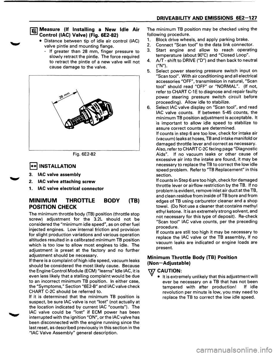
Control (lAC) Valve) (Fig. 6E2-82)
• Distance between tip of idle air control (lAC)
valve pintle and mounting flange.
-
If greater than 28 mm, finger pressure to
slowly retract the pintle. The force required
to retract the pintle
of a new valve will not
cause damage to the valve.
Fig. 6E2-82
E) INSTALLATION
3. lAC valve assembly
2. lAC valve attaching screw
1. lAC valve electrical connector
MINIMUM THROTTLE BODY (TB)
POSITION CHECK
The minimum throttle body (TB) position (throttle stop
screw) adjustment
for the 3.2L should not be
considered the
"minimum idle speed", as on other fuel
injected engines. Low internal friction and provision
for slight production variations and various operation
altitudes resulted in a calibrated
minimum TB position
which is too
low to allow most engines to idle. The
adjustment is preset at the factory and no further
adjustment should be necessary.
If there is a complaint of high idle speed, vacuum leaks
should be considered the
most likely cause. Because
the Engine
Control Module (ECM) "learns" Idle lAC, it is
even less likely
that a stalling complaint would be due
to
an incorrect minimum TB position. In either case,
the
"Symptoms," Section "6E2-B" and lAC valve check
CHART C-2C should be referred to.
If it is determined that the minimum TB position is
suspect,
be sure lAC valve is not "lost'' (not actually at
the location indicated by current
lAC "counts"). The
lAC valve could be "lost" if ECM power has been
interrupted
with the ignition "ON", or the lAC valve has
been disconnected
with the engine running since the
last reset,
as described previously in this section in the
"lAC Valve Assembly" general description.
DRIVEABILITY AND EMISSIONS 6E2-127
The minimum TB position may be checked using the
following procedure.
1. Block drive wheels, and apply parking brake.
2. Connect "Scan tool" to the data link connector.
3. Start engine and allow to reach operating
temperature (about
go•q and "Closed Loop".
4. A/T-shift to DRIVE ("D") and then back to neutral
("N").
5. Select power steering pressure switch input on
"Scan tool". With air conditioning and all electrical
accessories
"OFF", transmission in natural, "Scan
tool" should read "OFF" or "NORMAL". (If not,
refer to
CHART C-1 E to diagnose and repair faulty
power steering pressure switch circuit before
proceeding).
Allow idle to stabilize.
6. Select lAC valve display on "Scan tool", and read
lAC valve counts. If between 5-45 counts, the
minimum
TB position adjustment is acceptable. It
is important to allow idle speed to stabilize to
assure correct counts are determined.
If counts in step 6 are too low, check for intake air
(vacuum) leaks at hoses,
TB and intake manifold or
damaged throttle lever and correct as necessary.
Also, refer to
CHART C-2C facing page "Diagnostic
Aids". If no vacuum leaks or other cause of
excessive air into the intake are found, it may be
necessary
to replace the TB to correct the low idle
speed problem. Refer to
"TB Replacement" in this
section.
If counts in Step 6 are too high, check for damaged
throttle lever or airflow restriction by the
TB. If no
problem is evident, remove inlet air
duct at the TB,
and
clean residue from inside of TB bore and from
edges of TB using carburetor cleaner and a shop
towel. (Do Not use a cleaner that contains methyl
ethyl ketone.
It is an extremely strong solvent, and
not necessary for this type of deposit). Re-check
"Scan tool" lAC valve counts, per the preceding
procedure.
If counts are still too high it may be necessary to
replace the
lAC valve or the TB assembly, If no
vacuum leaks are indicated
or engine loads are
present.
Minimum Throttle Body (TB) Position
(Non-Adjustable)
\fl CAUTION:
VI • It is extremely unlikely that this adjustment will
ever be necessary on a TB that has not been
tampered
with after production! If idle
revolution per minute is low, you may need
to
replace the TB to correct the low idle speed.
Page 827 of 1928
DRIVEABILITY AND EMISSIONS 6E2-131
CHART C-2C
IDLE AIR CONTROL (lAC) SYSTEM CHECK
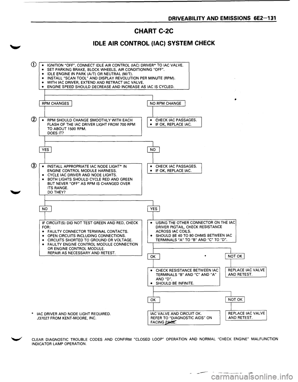
CD • IGNITION "OFF", CONNECT IDLE AIR CONTROL (lAC) DRIVER* TO lAC VALVE. • SET PARKING BRAKE, BLOCK WHEELS, AIR CONDITIONING "OFF".
• IDLE ENGINE IN PARK (A/T) OR NEUTRAL (MIT). • INSTALL "SCAN TOOL" AND DISPLAY REVOLUTION PER MINUTE (RPM). • WITH lAC DRIVER, EXTEND AND RETRACT lAC VALVE. • ENGINE SPEED SHOULD DECREASE AND INCREASE AS lAC IS CYCLED.
I
1 I • RPM CHANGES I NO RPM CHANGE I
I I • RPM SHOULD CHANGE SMOOTHLY
WITH EACH • CHECK lAC PASSAGES.
I FLASH OF THE lAC DRIVER LIGHT FROM 700 RPM • IF OK, REPLACE lAC.
TO ABOUT 1500 RPM. DOES IT?
I
~ cf
• INSTALL APPROPRIATE lAC NODE LIGHT* IN • CHECK lAC PASSAGES.
l ENGINE CONTROL MODULE HARNESS. • IF OK, REPLACE lAC. ®
• CYCLE lAC
DRIVER AND NODE LIGHTS.
• BOTH LIGHTS SHOULD CYCLE RED AND GREEN BUT NEVER "OFF" AS RPM IS CHANGED OVER
ITS RANGE. DO THEY?
I
cf ~ IF CIRCUIT(S) DID NOT TEST GREEN AND RED, CHECK •
USING THE OTHER CONNECTOR ON THE lAC
FOR: DRIVER
PIGTAIL, CHECK RESISTANCE
•
FAULTY CONNECTOR TERMINAL CONTACTS. ACROSS
lAC COILS.
• OPEN CIRCUITS INCLUDING CONNECTIONS. •
SHOULD BE 40 TO 80 OHMS BETWEEN lAC
• CIRCUITS SHORTED TO GROUND OR VOLTAGE. TERMINALS "A" TO "B" AND "C" TO "D".
• FAULTY ENGINE CONTROL MODULE CONNECTION I OR ENGINE CONTROL MODULE.
~
l REPAIR AS NECESSARY AND RETEST. l NOT OK I .
_l
• CHECK RESISTANCE BETWEEN lAC I REPLACE lAC VALVE I TERMINALS "B" AND "C" AND "A" AND RETEST. AND "D". • SHOULD BE INFINITE.
I
~
l
I NOT OK I
]
AC DRIVER AND NODE LIGHT REQUIRED. * I J lAC VALVE AND CIRCUIT OK. I REPLACE lAC VALVE J 37027 FROM KENT-MOORE, INC. REFER TO "DIAGNOSTIC AIDS" ON AND RETEST. FACING~
~ CLEAR DIAGNOSTIC TROUBLE CODES AND CONFIRM "CLOSED LOOP" OPERATION AND NORMAL "CHECK ENGINE" MALFUNCTION
INDICATOR LAMP OPERATION.
------
Page 874 of 1928
7A-2 AUTOMATIC TRANSMISSION (4L30-E)
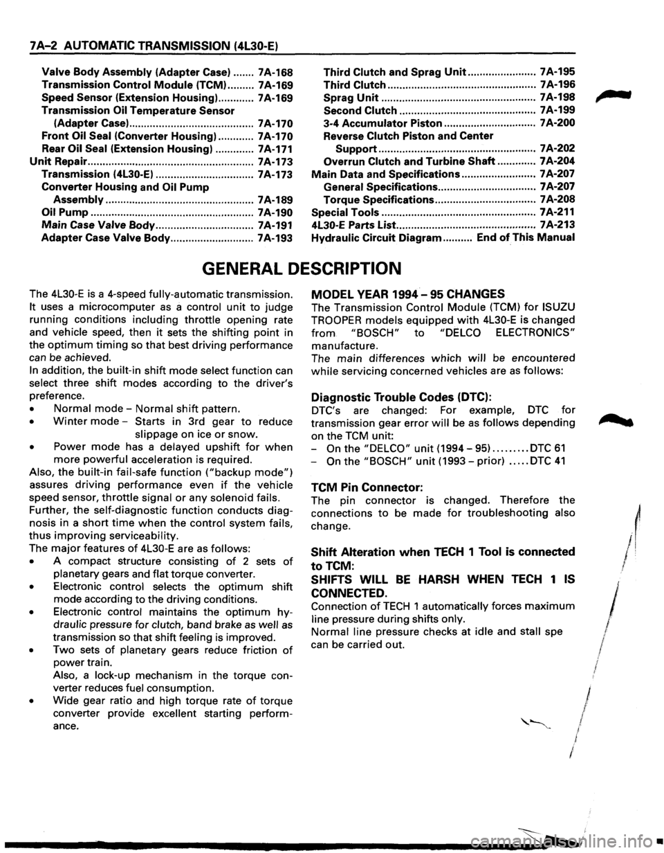
Valve Body Assembly (Adapter Case) ....... 7A-168 Third Clutch and Sprag Unit ....................... 7A-195
Transmission Control
Module (TCM) ......... 7A-169 Third Clutch .................................................. 7A-196
Speed Sensor (Extension Housing) ............ 7A-169 Sprag
Unit ....................................................
7A-198
Transmission
Oil Temperature Sensor Second
Clutch .............................................. 7A-199
(Adapter Case) ..........................................
7A-170 3-4 Accumulator Piston ............................... 7A-200
Front Oil Seal (Converter Housing) ............ 7A-170 Reverse Clutch Piston and Center
Rear
Oil Seal (Extension Housing) ............. 7A-171 Support ..................................................... 7 A-202
Unit Repair ........................................................ 7A-173 Overrun Clutch and Turbine Shaft ............. 7A-204
Transmission (4L30-E) ................................. 7A-173 Main Data and Specifications ......................... 7 A-207
Converter Housing and Oil Pump General
Specifications ................................. 7 A-207
Assembly .................................................. 7 A-189 Torque
Specifications .................................. 7A-208
Oil
Pump ....................................................... 7A-190 Special Tools .................................................... 7A-211
Main Case Valve Body ................................. 7A-191 4L30-E Parts List.. ............................................. 7A-213
Adapter Case Valve Body ............................ 7A-193 Hydraulic
Circuit Diagram .......... End of This Manual
GENERAL DESCRIPTION
The 4L30-E is a 4-speed fully-automatic transmission.
It uses a microcomputer as a control unit to judge
running conditions
including throttle opening rate
and vehicle speed, then
it sets the shifting point in
the
optimum timing so that best driving performance
can be achieved.
In addition, the built-in shift mode select function can
select three shift modes according to the driver's
preference.
• Normal mode-Normal shift pattern.
• Winter mode-Starts in 3rd gear to reduce
slippage on ice
or snow.
• Power mode has a delayed upshift for when
more powerful acceleration is required.
Also, the built-in fail-safe
function ("backup mode")
assures driving performance even if the vehicle
speed sensor,
throttle signal or any solenoid fails.
Further, the self-diagnostic
function conducts diag
nosis in a short time when the control system fails,
thus improving serviceability.
The major features of 4L30-E are as follows:
• A compact structure consisting of 2 sets of
planetary gears and flat torque converter.
• Electronic control selects the optimum shift
mode according
to the driving conditions.
• Electronic control maintains the optimum hy
draulic pressure for clutch, band brake as well as
transmission so that shift feeling is improved.
• Two sets of planetary gears reduce friction of
power train.
Also, a lock-up mechanism in the torque con
verter reduces fuel consumption.
• Wide gear ratio and high torque rate of torque
converter provide
excellent starting perform
ance.
MODEL YEAR 1994-95 CHANGES
The Transmission Control Module (TCM) for ISUZU
TROOPER
models equipped with 4L30-E is changed
from "BOSCH" to "DELCO ELECTRONICS"
manufacture.
The main differences
which will be encountered
while servicing concerned vehicles are as follows:
Diagnostic Trouble Codes (DTC):
DTC's are changed: For example, DTC for
transmission gear error will be as follows depending
on the TCM unit:
-
On the "DELCO" unit (1994-95) ......... DTC 61
-On the "BOSCH" unit (1993-prior) ..... DTC 41
TCM Pin Connector:
The pin connector is changed. Therefore the
connections
to be made for troubleshooting also
change.
Shift Alteration when TECH 1 Tool is connected
toTCM:
SHIFTS WILL BE HARSH WHEN TECH 1 IS
CONNECTED.
Connection of TECH 1 automatically forces maximum
line pressure during shifts only.
Normal line pressure checks at idle and stall spe
can be carried out.
/
/
I J I
/
l
•
Page 875 of 1928
(
f
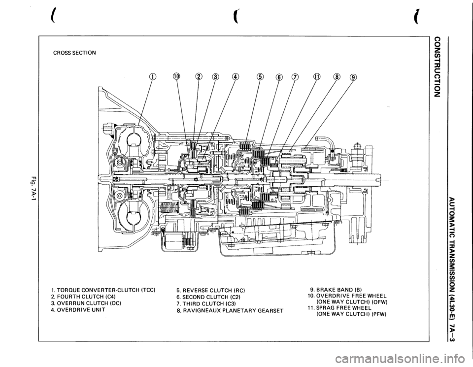
CROSS
SECTION
"'T1 ce· ~ .....
1. TORQUE CONVERTER-CLUTCH (TCC)
5.
REVERSE
CLUTCH (RC)
2.
FOURTH CLUTCH (C4)
6.
SECOND
CLUTCH (C2)
3.
OVERRUN CLUTCH
(OC)
7.
THIRD
CLUTCH (C3)
4. OVERDRIVE
UNIT
8.
RAVIGNEAUX
PLANETARY
GEARSET
9.
BRAKE
BAND (B)
10.
OVERDRIVE
FREE WHEEL
(ONE
WAY
CLUTCH) (OFW)
11.
SPRAG
FREE WHEEL
(ONE WAY
CLUTCH)
(PFW)
(
(') 0 2 CJ) -1 ::D c (') ::! 0 2
)> c: -f 0 s: )> -f n -f ::D )> 2 en s: c;; en s 2 -;; ,... w 0 I m -...... )> I w