check engine ISUZU TROOPER 1995 Workshop Manual
[x] Cancel search | Manufacturer: ISUZU, Model Year: 1995, Model line: TROOPER, Model: ISUZU TROOPER 1995Pages: 1928
Page 914 of 1928
7 A-42 AUTOMATIC TRANSMISSION (4L30-E)
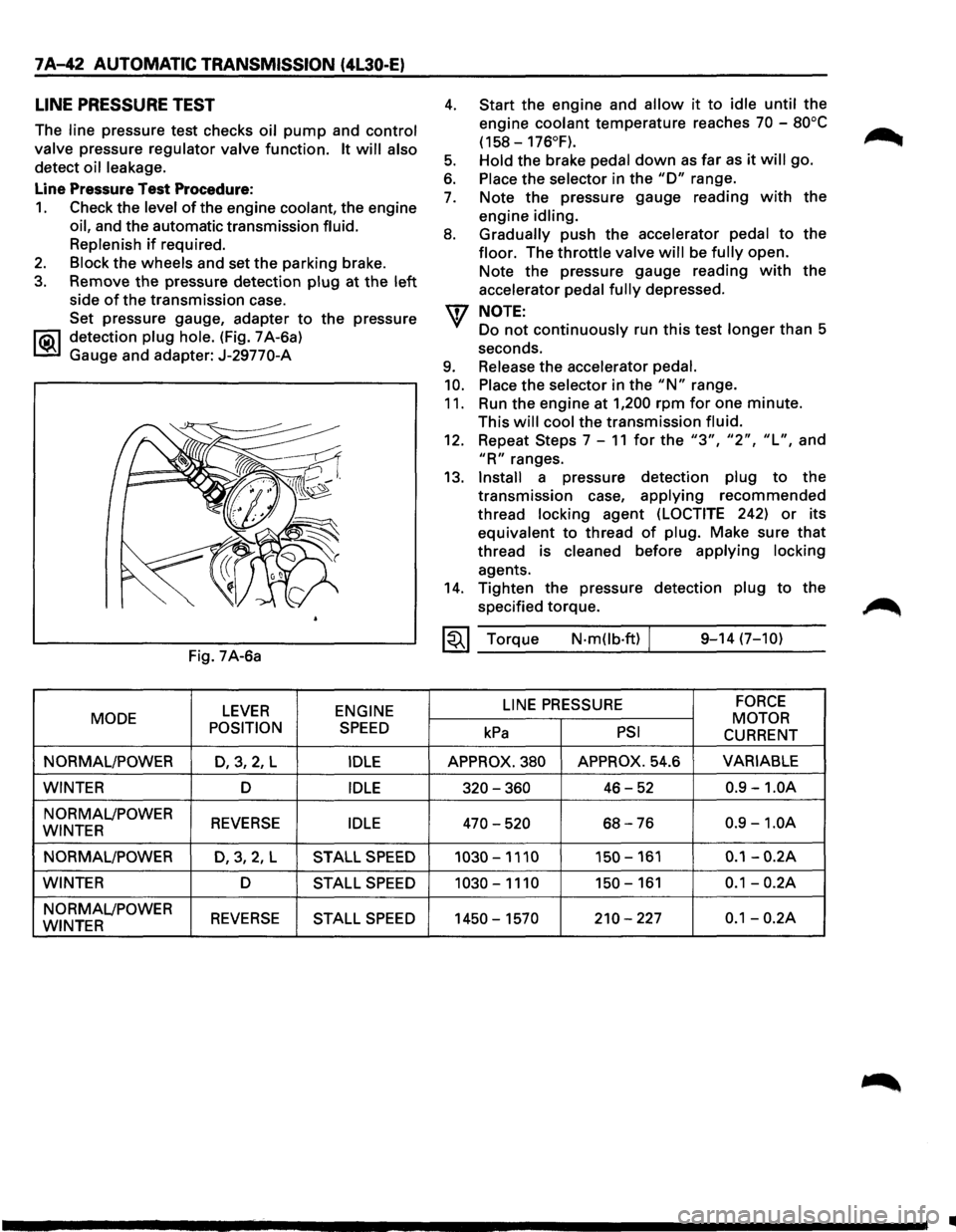
LINE PRESSURE TEST
The line pressure test checks oil pump and control
valve
pressure regulator valve function. It will also
detect oil leakage.
Line Pressure Test Procedure:
1. Check the level of the engine coolant, the engine
oil, and the automatic transmission fluid.
Replenish
if required.
2. Block the wheels and set the parking brake.
3. Remove the pressure detection plug at the left
side of the transmission case.
Set pressure gauge, adapter
to the pressure
l"iC\1 detection plug hole. (Fig. 7 A-6a)
~ Gauge and adapter: J-29770-A
Fig. 7A-6a
LEVER ENGINE
MODE
POSITION
SPEED
NORMAL/POWER D,3,2, L IDLE
WINTER D IDLE
NORMAL/POWER REVERSE IDLE WINTER
NORMAL/POWER
D,3,2,L STALL SPEED
WINTER D STALL SPEED
NORMAL/POWER REVERSE STALL SPEED WINTER
4.
5.
6.
7.
8.
9.
10.
11.
Start the engine and allow it to idle until the
engine
coolant temperature reaches 70 -80°C
(158-176°F).
Hold
the brake pedal down as far as it will go.
Place the selector in the "D" range.
Note the pressure gauge reading
with the
engine
idling.
Gradually
push the accelerator pedal to the
floor. The throttle valve will be fully open.
Note the pressure gauge reading
with the
accelerator
pedal fully depressed.
NOTE:
Do not continuously run this test longer than 5
seconds.
Release the accelerator pedal.
Place
the selector in the "N" range.
Run the engine at
1,200 rpm for one minute.
This
will cool the transmission fluid.
12. Repeat Steps 7-11 for the "3", "2", "L", and
"R" ranges.
13.
Install a pressure detection plug to the
transmission case,
applying recommended
thread
locking agent (LOCTITE 242) or its
equivalent to thread
of plug. Make sure that
thread is cleaned before applying locking
agents.
14. Tighten the pressure detection plug to the
specified torque.
~~~ Torque N·mOb·ft) / 9-14 (7-10)
LINE
PRESSURE FORCE
MOTOR kPa PSI CURRENT
APPROX. 380 APPROX. 54.6 VARIABLE
320-360 46-52 0.9 -1.0A
470-520 68-76 0.9 -1.0A
1030-1110 150-161 0.1-0.2A
1030-1110 150-161 0.1-0.2A
1450-1570 210-227 0.1-0.2A
•
Page 917 of 1928
ELECTRONIC DIAGNOSIS
HOW TO DIAGNOSE THE PROBLEM
~ 1. To avoid incorrect diagnostics: this book needs
to be followed accurately. Unless stated: do
not jump
directly to a section that could
contain the solution: some important
information may be missed.
2. The sections in CAPITALS and bold are the
main sections that can be found in the
contents.
3. The GOTO "SECTION" means to continue to
check going to the "section".
4. The GOTHROUGH "SECTION" means to go
through the "section" and then to go back to
the place the GOTHROUGH was written.
5. BASIC ELECTRIC CIRCUITS:
You should understand the basic theory of
electricity. This will include the meaning of
voltage, amps, ohms, and what happens in a
circuit with an open or shorted wire. You
should also be able to read and understand
wiring diagrams.
6. IGNITION CYCLE:
When the car is driven a malfunction can occur
due to a car wiring harness problem, in this
case the driver can reset the system (as on a
personal computer). To reset the computer he
must: (
1) Stop the car and the engine.
(2) Turn the key ignition OFF.
(3) Turn the key ignition ON.
AUTOMATIC TRANSMISSION (4L30·E) 7 A-45
Page 919 of 1928
DIAGNOSTIC CHECK
This test determines if the transmission itself or its
~ inputs or outputs connections or sensors are failing.
IF you have a scan tool TECH1:
NO: Use the CHECK TRANS Indicator diagnostic
codes
GOTO FLASHING CODES.
YES:
1. Connect the TECH1: GOTHROUGH TECH1
CONNECTION.
2. Turn on the ignition but not the engine.
3. Push "F2" on TECH1 to see the Diagnostic
Trouble Code (OTC):
4. IF you have DTC?
YES: write down all code numbers and do the
DTCCHECK
NO: the DTC can not help you finding the
problem.
(1) GOTHROUGH "CHECK TRANS" CHECK
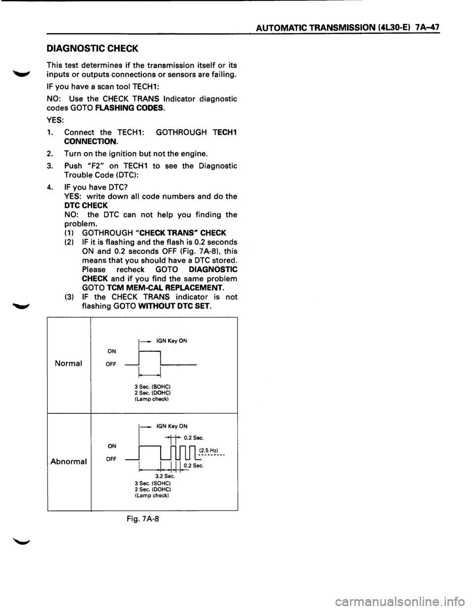
(2) IF it is flashing and the flash is 0.2 seconds
ON and 0.2 seconds OFF (Fig. 7A-8), this
means that you
should have a DTC stored.
Please recheck GOTO DIAGNOSTIC
CHECK and if you find the same problem
GOTO
TCM MEM-CAL REPLACEMENT.
(3) IF the CHECK TRANS indicator is not
........,. flashing GOTO WITHOUT DTC SET.
ON
~-IGNKeyON
__fL__ Normal OFF
w
3 Sec. (SOHC) 2 Sec. (DOHC} (Lamp check)
~-IGNKeyON
ON
~~ 0.2Sec.
~~~5-~=~--
Abnormal OFF
I. I Ill 0.2 Sec. I I I I I 3.2 Sec. 3 Sec. (SOHC) 2 Sec. (DOHC) (Lamp check}
Fig. 7A-8
AUTOMATIC TRANSMISSION (4L30-E) 7 A-47
Page 920 of 1928
7 A-48 AUTOMATIC TRANSMISSION (4L30-E)
"CHECK TRANS" CHECK
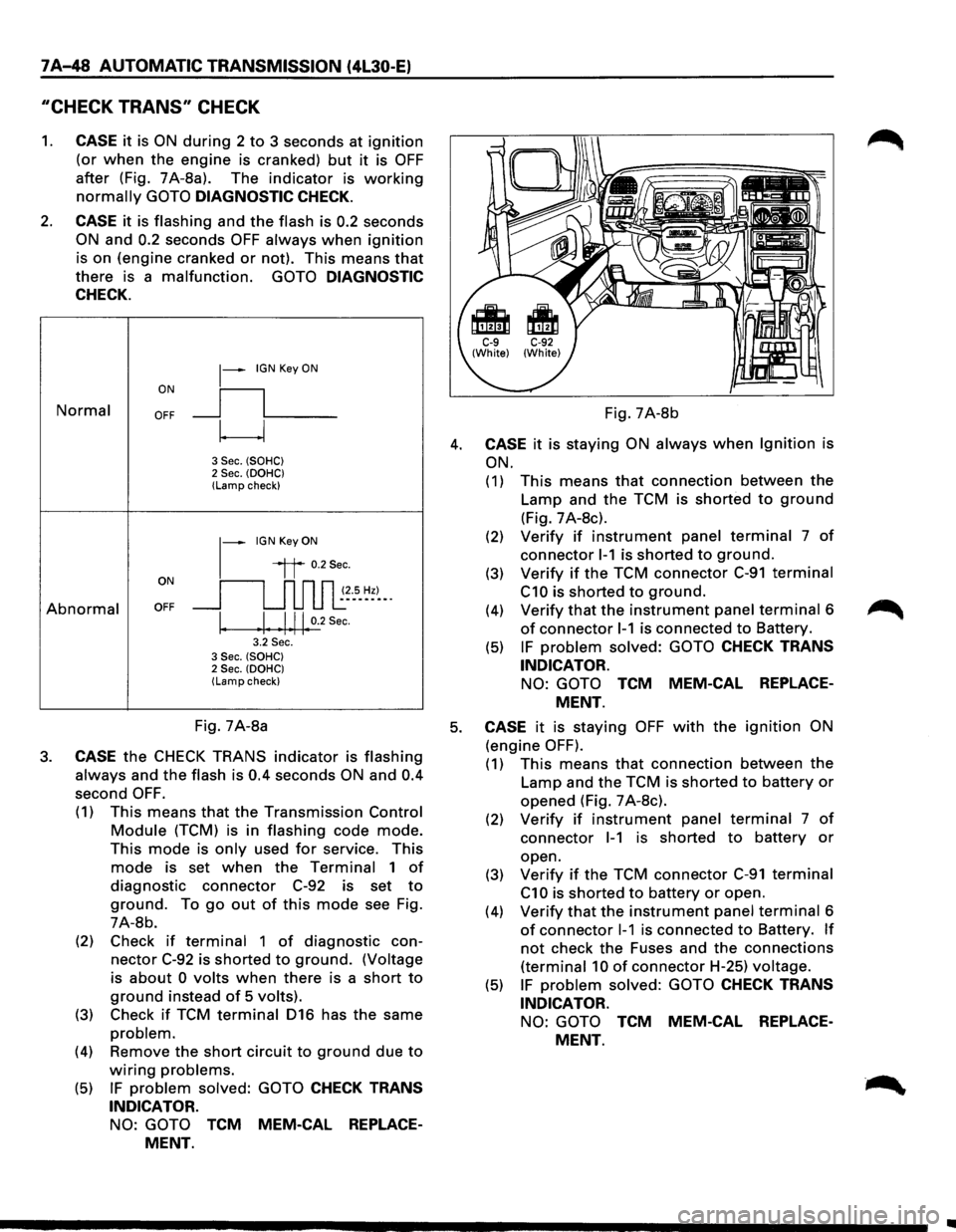
1. CASE it is ON during 2 to 3 seconds at ignition
(or when the engine is cranked) but it is OFF
after (Fig. 7A-8a). The indicator is working
normally GOTO DIAGNOSTIC CHECK.
2. CASE it is flashing and the flash is 0.2 seconds
ON and 0.2 seconds OFF always when ignition
is on (engine cranked or not). This means that
there is a malfunction. GOTO DIAGNOSTIC
CHECK.
Normal
Abnormal
~-IGN Key ON
ON
II
OFF __j l___
~
3 Sec. (SOHC) 2 Sec. (OOHC) (Lamp check)
1-
IGN Key ON
il 0.2Sec.
oN 11 n n n ~~--s_ ~~)-_. OFF __j u u u l:
I. .I. .1.11. 0.2
Sec.
3.2 Sec. 3 Sec. (SOHC) 2 Sec. (OOHC) (Lamp check)
Fig. 7A-8b
4. CASE it is staying ON always when Ignition is
ON.
(1) This means that connection between the
Lamp and the TCM is shorted to ground
(Fig. 7 A-8c).
(2) Verify if instrument panel terminal 7 of
connector 1-1 is shorted to ground.
(3) Verify if the TCM connector C-91 terminal
C10 is shorted to ground.
(4) Verify that the instrument panel terminal 6
of connector 1-1 is connected to Battery.
(5) IF problem solved: GOTO CHECK TRANS
INDICATOR.
NO: GOTO TCM MEM-CAL REPLACE
MENT.
Fig. 7A-8a 5. CASE it is staying OFF with the ignition ON
(engine OFF). 3. CASE the CHECK TRANS indicator is flashing
always and the flash is 0.4 seconds ON and 0.4
second OFF.
(1) This means that the Transmission Control
Module (TCM) is in flashing code mode.
This mode is only used for service. This
mode is set when the Terminal 1 of
diagnostic connector C-92 is set to
ground. To go out of this mode see Fig.
7A-8b.
(2) Check
if terminal 1 of diagnostic con
nector C-92 is shorted to ground. (Voltage
is
about 0 volts when there is a short to
ground instead of 5 volts).
(3) Check if TCM terminal 016 has the same
problem.
(4) Remove the short circuit to ground due to
wiring problems.
(5) IF problem solved: GOTO CHECK TRANS
INDICATOR.
NO: GOTO TCM MEM-CAL REPLACE
MENT.
(1) This means that connection between the
Lamp and the TCM is shorted to battery or
opened (Fig. 7 A-8c).
(2) Verify if instrument panel terminal 7 of
connector 1-1 is shorted to battery or
open.
(3)
Verify if the TCM connector C-91 terminal
C1 0 is shorted to battery or open.
(4)
Verify that the instrument panel terminal 6
of connector 1-1 is connected to Battery. If
not check the Fuses and the connections
(terminal 10 of connector H-25) voltage.
(5) IF problem solved: GOTO CHECK TRANS
INDICATOR.
NO: GOTO TCM MEM-CAL REPLACE
MENT.
Page 935 of 1928
AUTOMATIC TRANSMISSION (4L30-E) 7 A-63
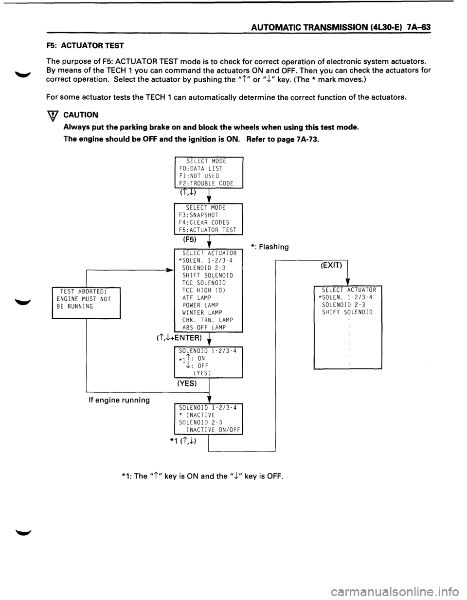
F5: ACTUATOR TEST
The purpose
of F5: ACTUATOR TEST mode is to check for correct operation of electronic system actuators.
By means of the TECH 1 you can command the actuators ON and OFF. Then you can check the actuators for
correct operation.
Select the actuator by pushing the "i" or".!." key. (The* mark moves.)
For some actuator tests the TECH 1
can automatically determine the correct function of the actuators.
W CAUTION
Always put the parking brake on and block the wheels when using this test mode.
The engine
should be OFF and the ignition is ON. Refer to page 7A-73.
TEST ABORTED! ENGINE MUST NOT BE RUNNING
If engine running
SELECT MODE FO: DATA LIST
F1:NOT USED F2:TROUBLE CODE
(T,.J..)
SELECT MODE
F3:SNAPSHOT F4:CLEAR CODES
F5:ACTUATOR TEST
(F5)
SELECT ACTUATOR *SOLEN. 1-2/3-4 SOLENOID 2-3
SHIFT SOLENOID TCC SOLENOID TCC HIGH CD)
ATF LAMP POWER LAMP WINTER LAMP
CHK. TRN. LAMP ABS OFF LAMP
(i,.!.+ENTER)
SOLENOID 1-2/3-4
*1 i: ON .j,: OFF
CYESJ
(YES)
SOLENOID 1-2/3-4 * INACTIVE SOLENOID 2-3 INACTIVE ON/OFF
* 1 (i,.!.)
*:Flashing
*1: The
"i" key is ON and the".!." key is OFF.
(EXIT)
SELECT ACTUATOR *SOLEN. 1-2/3-4 SOLENOID 2-3 SHIFT SOLENOID
Page 939 of 1928
AUTOMATIC TRANSMISSION (4L30-E) 7 A~7
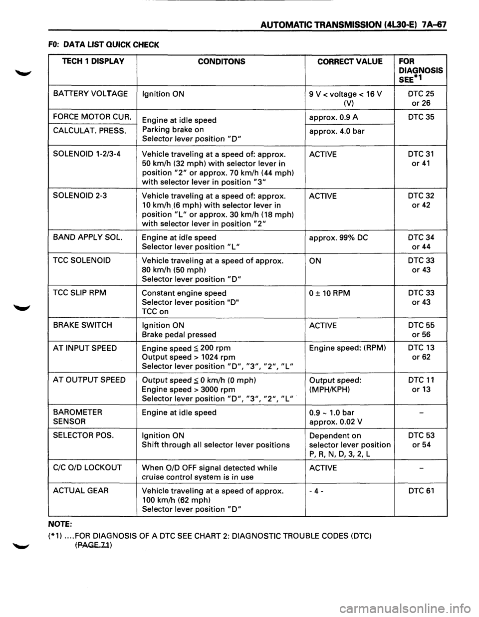
FO: DATA LIST QUICK CHECK
TECH 1
DISPLAY
CONDITONS CORRECT VALUE
BATIERY VOLTAGE
Ignition ON 9 V < voltage < 16 V
(V)
FORCE MOTOR CUR. Engine at idle speed approx. 0.9 A
CALCULAT. PRESS. Parking
brake on
approx. 4.0 bar Selector lever position "D"
SOLENOID 1-2/3-4
Vehicle traveling at a speed of: approx. ACTIVE
50 km/h (32 mph) with selector lever in
position
"2" or approx. 70 km/h (44 mph)
with selector lever in position "3"
SOLENOID 2-3
Vehicle traveling at a speed of: approx. ACTIVE
10 km/h_(6 mph) with selector lever in
position
"L" or approx. 30 km/h (18 mph)
with selector lever in position "2"
BAND APPLY SOL. Engine at idle speed
approx. 99% DC
Selector lever position "L"
TCC SOLENOID Vehicle traveling at a speed of approx. ON
80 km/h (50 mph)
Selector lever position "D"
TCC SLIP RPM Constant engine speed 0 ± 10 RPM
Selector lever position "D"
TCCon
BRAKE SWITCH
Ignition ON ACTIVE
Brake pedal pressed
AT
INPUT SPEED Engine speed :;:; 200 rpm Engine speed: (RPM)
Output speed> 1024 rpm
Selector lever position "D", "3", "2", "L"
AT OUTPUT SPEED Output speed:;:; 0 km/h (0 mph) Output speed:
Engine speed >
3000 rpm (MPH/KPH)
Selector lever position "D", "3", "2", "L" ·
BAROMETER
Engine at idle speed 0.9-1.0 bar
SENSOR approx. 0.02 V
SELECTOR POS. Ignition ON Dependent on
Shift through all selector lever positions selector lever position
P, R, N, D, 3, 2, L
C!C OlD LOCKOUT When 0/D OFF signal detected while ACTIVE
cruise control system is in use
ACTUAL GEAR Vehicle traveling at a speed of approx. - 4 -
100 km/h (62 mph)
Selector lever position
"D"
NOTE:
(*1) .... FOR DIAGNOSIS OF A DTC SEE CHART 2: DIAGNOSTIC TROUBLE CODES (DTC)
tPAGE..ll)
FOR
DIAGNOSIS
SEE*1
DTC25
or 26
DTC35
DTC 31
or 41
DTC32
or 42
DTC34
or 44
DTC33
or 43
DTC33
or 43
DTC55
or 56
DTC 13
or 62
DTC 11
or13
-
DTC53
or 54
-
DTC 61
Page 940 of 1928
7A-68 AUTOMATIC TRANSMISSION (4l30-E)
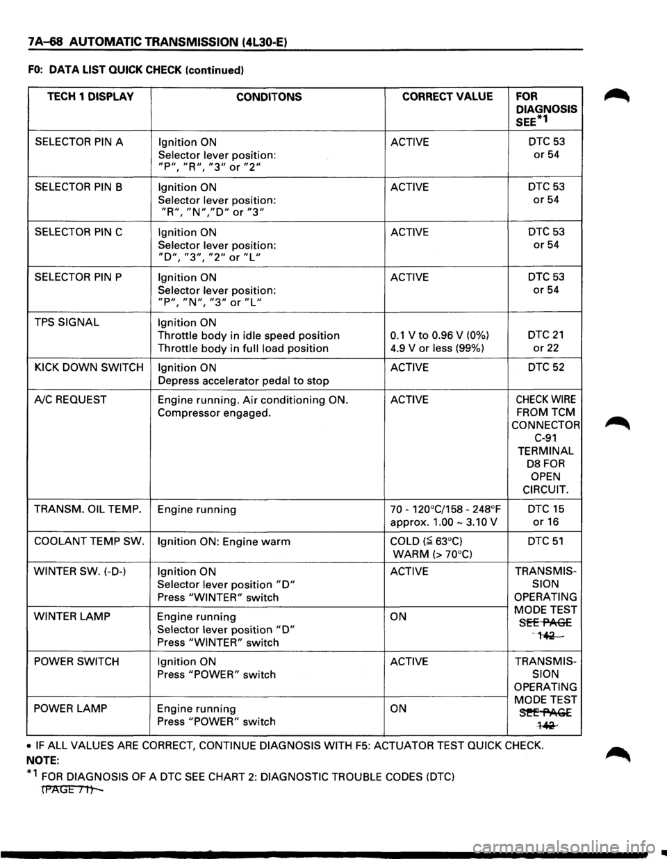
FO: DATA LIST QUICK CHECK (continued)
TECH 1 DISPLAY
CONDITONS CORRECT VALUE FOR
DIAGNOSIS
SEE*1
SELECTOR PIN A Ignition ON ACTIVE DTC 53
Selector lever position: or 54
"P11, "R'', "311 or "211
SELECTOR PIN B Ignition ON ACTIVE DTC53
Selector lever position: or 54
"R11
, "N","D'' or "3''
SELECTOR PIN C Ignition ON ACTIVE DTC 53
Selector lever position: or 54
"D'', "311
, "211 or "L''
SELECTOR PIN P Ignition ON ACTIVE DTC 53
Selector lever position: or 54
"P11
, "N11, "311 or "Lu
TPS SIGNAL Ignition ON
Throttle body in idle speed position 0.1 V to 0.96 V (0%) DTC 21
Throttle body in full load position 4.9
V or less (99%) or 22
KICK DOWN SWITCH Ignition ON ACTIVE DTC 52
Depress accelerator pedal to stop
A!C REQUEST Engine running. Air conditioning ON. ACTIVE CHECK WIRE
Compressor
engaged. FROM TCM
CONNECTOR
C-91
TERMINAL
DB FOR
OPEN
CIRCUIT.
TRANSM. OIL
TEMP.
Engine running 70 -120°C/158 -248°F DTC 15
approx. 1.00 -3.10 V or16
COOLANT TEMP SW.
Ignition ON: Engine warm COLD (~ 63°C) DTC 51
WARM (> 70°C)
WINTER SW.
(-D-) Ignition ON ACTIVE TRANS
MIS-
Selector
lever position "D" SION
Press "WINTER" switch OPERATING
WINTER
LAMP Engine running ON MODE
TEST Sff-flAG£ Selector lever position "D" -,~ Press "WINTER" switch
POWER SWITCH Ignition ON ACTIVE TRANSMIS-
Press "POWER" switch SION
OPERATING
POWER LAMP Engine running ON MODE TEST
3!'Ef'AGE Press "POWER" switch l~·
• IF ALL VALUES ARE CORRECT, CONTINUE DIAGNOSIS WITH F5: ACTUATOR TEST QUICK CHECK.
NOTE:
*1
FOR DIAGNOSIS OF A DTC SEE CHART 2: DIAGNOSTIC TROUBLE CODES (DTC)
(PAGE Itt-
IIIII
Page 945 of 1928
AUTOMATIC TRANSMISSION (4L30-E) 7A-73
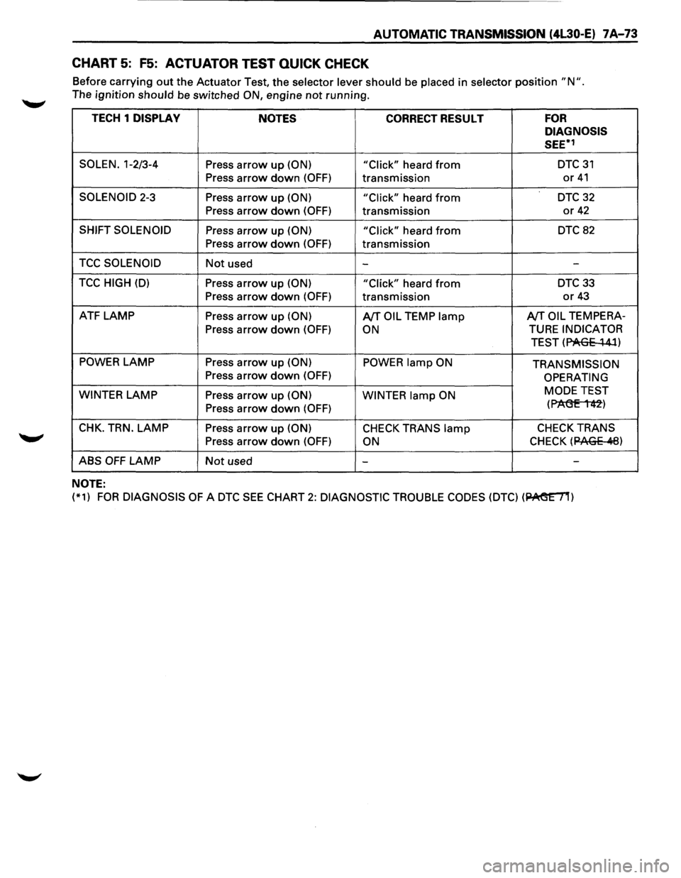
CHART 5: F5: ACTUATOR TEST QUICK CHECK
Before carrying out the Actuator Test, the selector lever should be placed in selector position "N ".
The ignition should be switched ON, engine not running.
TECH 1 DISPLAY
NOTES CORRECT RESULT FOR
DIAGNOSIS
SEE*1
SOLEN. 1-2/3-4 Press arrow up (ON)
"Click" heard from DTC31
Press
arrow down (OFF) transmission or 41
SOLENOID 2-3 Press arrow up (ON) "Click" heard from DTC 32
Press arrow down (OFF) transmission or 42
SHIFT SOLENOID Press arrow up (ON)
"Click" heard from DTC 82
Press arrow down (OFF) transmission
TCC SOLENOID Not used --
TCC HIGH (D) Press arrow up (ON)
"Click" heard from DTC33
Press
arrow down (OFF) transmission or 43
ATF LAMP Press arrow up (ON) A/TOIL TEMP lamp A/TOIL TEMPERA-
Press
arrow down (OFF) ON TURE INDICATOR
TEST (PAGE
~ 41)
POWER LAMP
Press arrow up (ON) POWER lamp ON TRANSMISSION Press arrow down (OFF) OPERATING
WINTER
LAMP Press arrow up (ON)
WINTER lamp ON MODE
TEST
Press arrow down (OFF) (P1'\(3E 1 42)
CHK. TRN. LAMP Press arrow up (ON) CHECK TRANS lamp CHECK TRANS
Press arrow down (OFF) ON CHECK (12AGE .11:8)
ABS OFF LAMP Not used - -
NOTE:
(*1) FOR DIAGNOSIS OF A DTC SEE CHART 2: DIAGNOSTIC
TROUBLE CODES (DTC) (~)
Page 946 of 1928
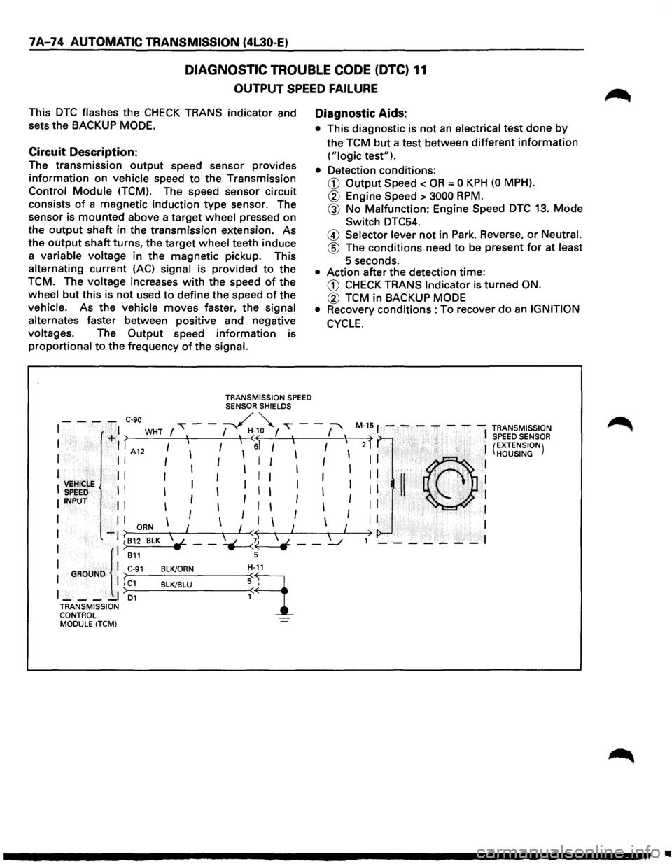
7 A-74 AUTOMATIC TRANSMISSION (4l30-E)
DIAGNOSTIC TROUBLE CODE (DTC) 11
OUTPUT SPEED FAILURE
This DTC flashes the CHECK TRANS indicator and
sets the
BACKUP MODE.
Circuit Description:
The transmission output speed sensor provides
information on vehicle speed to the Transmission
Control Module (TCM). The speed sensor circuit
consists
of a magnetic induction type sensor. The
sensor is
mounted above a target wheel pressed on
the
output shaft in the transmission extension. As
the
output shaft turns, the target wheel teeth induce
a variable voltage in the magnetic pickup. This
alternating current
(AC) signal is provided to the
TCM. The voltage increases with the speed of the
wheel
but this is not used to define the speed of the
vehicle. As the vehicle
moves faster, the signal
alternates faster between positive and negative
voltages. The
Output speed information is
proportional to the frequency of the signal.
TRANSMISSION SPEED SENSOR SHIELDS
Diagnostic Aids:
• This diagnostic is not an electrical test done by
the TCM but a test between different information
("logic test").
• Detection conditions:
CD Output Speed < OR = 0 KPH (0 MPH).
® Engine Speed > 3000 RPM.
@ No Malfunction: Engine Speed DTC 13. Mode
Switch DTC54.
@ Selector lever not in Park, Reverse, or Neutral.
@ The conditions need to be present for at least
5 seconds.
• Action after the detection time:
CD CHECK TRANS Indicator is turned ON.
® TCM in BACKUP MODE
•
Recovery conditions :To recover do an IGNITION
CYCLE.
- - -,.,.. C-90 "" - -~ ~ ""\' - -:-' M-15 r - - - - - - -TRANSMISSION I I WHT I , I , H<~o I , I , t , I SPEED SENSOR I +I > I I I I 6 I I I I 2 I (EXTENSION) I A12 I I I HOUSING
I II 111
11111111 ©I
', VEHICLE ', II I
I I I I I I I I I I !I ' ,~, 1
:
SPEED . I I I I I I I I I II "-.
I INPUT I I I I I I I I I I
I I I
ORN I I I I I I I I
I
-1 ~812 BLK l-- -~b - -~ ,> - - - - - - -I
I ll B11 s
I GROUND I C-91 BLK/ORN H-9_11
I I I C1 BLK/BLU : I
J __ -_I D1
TRANSMISSION
CONTROL MODULE
(TCM)
•
Page 950 of 1928
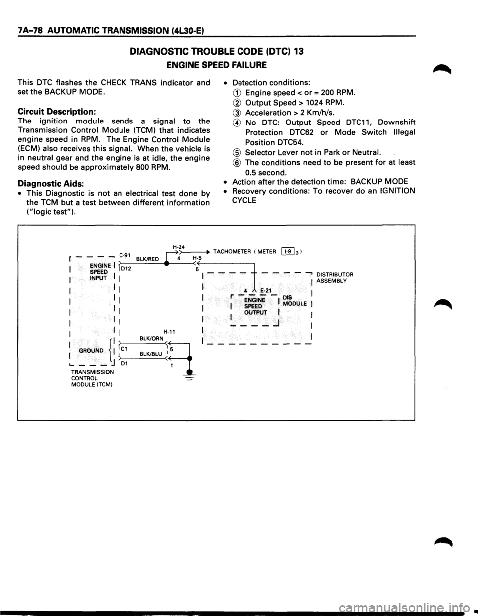
7A-78 AUTOMATIC TRANSMISSION (4L30-E)
DIAGNOSTIC TROUBLE CODE (DTC) 13
ENGINE SPEED FAILURE
This DTC flashes the CHECK TRANS indicator and
set the BACKUP
MODE.
Circuit Description:
The ignition module sends a signal to the
Transmission
Control Module (TCM) that indicates
engine speed in
RPM. The Engine Control Module
(ECM) also receives this signal. When the vehicle is
in
neutral gear and the engine is at idle, the engine
speed
should be approximately 800 RPM.
Diagnostic Aids:
• This Diagnostic is not an electrical test done by
the TCM but a test between different information
("logic test"). •
Detection
conditions:
CD Engine speed< or= 200 RPM.
@ Output Speed > 1024 RPM.
@ Acceleration > 2 Km/h/s.
@ No DTC: Output Speed DTC11, Downshift
Protection DTC62 or Mode Switch Illegal
Position DTC54.
@ Selector Lever not in Park or Neutral.
@ The conditions need to be present for at least
0.5
second.
• Action after the detection time: BACKUP MODE
•
Recovery conditions: To recover do an IGNITION
CYCLE
>--
-------t~lt--H--4~>-_4=.--+· TACHOMETER (METER [!1]31 r - - - -C-91 BLK/RED ~ H·S
I ENGINE I fD12 (A SPEED I I - - - - - - - --, DISTRIBUTOR I INPUT I I ASSEMBLy
I I I I 4 E-21 l I 1 r----ots 1 I I ENGINE I MODULE I
I II I I SPeED I OUTPUT 1
I II I ~---..J I
I I I H-11 I I
I GROUND {II fc1 BLK!ORN~q I_---------
I ) BLK/BLU ~ 1
'----j D1 TRANSMISSION CONTROL MODULE (TCMI
..