ignition ISUZU TROOPER 1995 Workshop Manual
[x] Cancel search | Manufacturer: ISUZU, Model Year: 1995, Model line: TROOPER, Model: ISUZU TROOPER 1995Pages: 1928
Page 970 of 1928
7 A-98 AUTOMATIC TRANSMISSION (4L30-E)
DIAGNOSTIC TROUBLE CODE (DTC) 33
TCC HIGH SHORT TO PLUS OR OPEN
This DTC flashes the CHECK TRANS indicator and
does NOT set the BACKUP MODE.
Circuit Description:
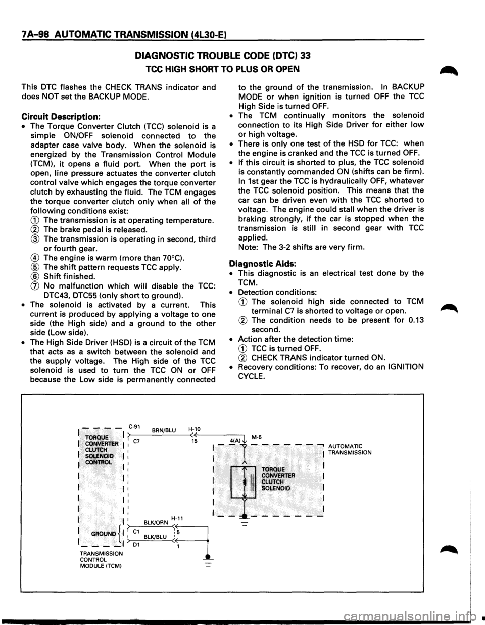
• The Torque Converter Clutch (TCC) solenoid is a
simple ON/OFF solenoid connected to the
adapter case valve body. When the solenoid is
energized
by the Transmission Control Module
(TCM), it opens a fluid port. When the port is
open,
line pressure actuates the converter clutch
control valve which engages the torque converter
clutch by exhausting the fluid. The TCM engages
the torque converter clutch only when all of the
following conditions exist:
G) The transmission is at operating temperature.
® The brake pedal is released.
® The transmission is operating in second, third
or fourth gear.
@ The engine is warm (more than 70°C).
® The shift pattern requests TCC apply.
® Shift finished.
(]) No malfunction which will disable the TCC:
DTC43, DTC55
(only short to ground).
• The solenoid is activated by a current. This
current is produced by applying a voltage to one
side (the High side) and a ground to the other
side (low side).
• The High Side Driver (HSD) is a circuit of the TCM
that acts as a switch between the solenoid and
the supply voltage. The High side of the TCC
solenoid is used to turn the TCC ON or OFF
because the Low side is permanently connected
to the ground of the transmission. In BACKUP
MODE
or when ignition is turned OFF the TCC
High Side is
turned OFF.
• The TCM continually monitors the solenoid
connection to its High Side Driver for either low
or high voltage.
• There is only one test of the HSD for TCC: when
the engine is cranked and the TCC is turned OFF.
•
If this circuit is shorted to plus, the TCC solenoid
is constantly commanded ON (shifts can be firm).
In 1st gear the TCC is hydraulically OFF, whatever
the TCC solenoid position. This means that the
car can be driven even with the TCC shorted to
voltage. The engine could stall when the driver is
braking strongly, if the car is stopped when the
transmission is still in second gear with TCC
applied. Note: The 3-2
shifts are very firm.
Diagnostic Aids:
• This diagnostic is an electrical test done by the
TCM.
• Detection conditions:
G) The solenoid high side connected to TCM
terminal C7 is shorted to voltage or open.
® The condition needs to be present for 0.13
second.
• Action after the detection time:
G) TCC is turned OFF.
® CHECK TRANS indicator turned ON.
•
Recovery conditions: To recover, do an IGNITION
CYCLE.
I - - - -C-91 BRN/BLU H-10
TOFlQU!;
I ? (( 4(A) J., M-6
I Cot!M:R'teR I I c7 15 I --1· -.-- - - ---. AUTOMATIC .. CLU'IrlilH I I S~NOib I I I TRANSMISSION
leoti~~~~ I . I I T()ftotJE
I I I I II CoHVEMER I I ' CLUTCH I I I I SQLENOID I
I 1: I I
I II I I I
I I H-11 - --!._-- - - - - -
{ I
{
BLK/ORN ~
9
-=-
1 GROUND I I C1 BLK/BLU : 5
1_--_,) 01 ( 1
TRANSMISSION
CONTROL MODULE (TCM)
•
Page 971 of 1928
IF you have a SCAN TOOL: TECH1?
L
$
AUTOMATIC TRANSMISSION (4L30-E) 7 A-99
DIAGNOSTIC TROUBLE CODE (OTC) 33
TCC HIGH SHORT TO PLUS OR OPEN
$
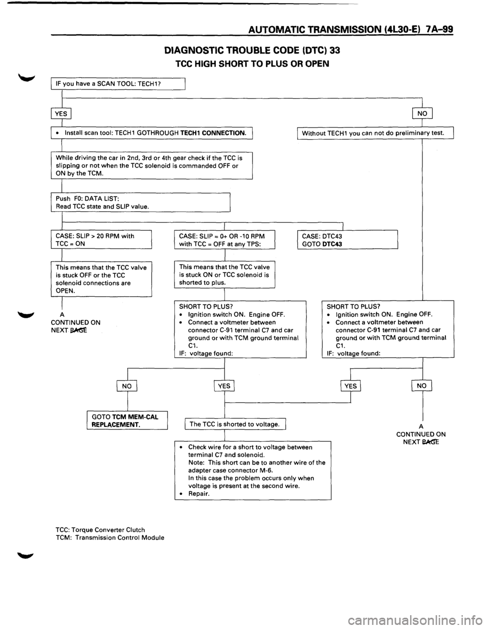
• Install scan tool: TECH1 GOTHROUGH TECH1 CONNECTION. I I Without TECH1 you can not do preliminary test.
l
While driving the car in 2nd, 3rd or 4th gear check if the TCC is
slipping or not when the TCC solenoid is commanded OFF or ON by the TCM.
I
Push FO: DATA LIST:
I Read TCC state and SLIP value.
l I I
CASE: SLIP > 20 RPM with CASE: SLIP= 0+ OR -10 RPM I CASE: DTC43
I TCC =ON with TCC = OFF at any TPS: GOTO DTC43
I
This means that the TCC valve This means that the TCC valve
is stuck OFF or the TCC is stuck ON or TCC solenoid is
solenoid connections are shorted to plus.
OPEN.
I SHORT TO PLUS? SHORT TO PLUS?
A
• Ignition switch ON. Engine OFF. • Ignition switch ON. Engine OFF.
CONTINUED ON • Connect a voltmeter between • Connect a voltmeter between
NEXT~ connector C-91 terminal C7 and car connector C-91 terminal C7 and car
ground or with TCM ground terminal ground or with TCM ground terminal C1. C1. IF: voltage found: IF: voltage found:
~
YES
$ s
I GOTO TCM MEM-CAL REPLACEMENT. I I The TCC is shorted to voltage. I A CONTINUED ON
Check
wire for a short to voltage between NEXT eAG"E • terminal C7 and solenoid. Note:
This short can be to another wire of the
adapter case connector M-6.
In this case the problem occurs only when voltage is present at the second wire.
• Repair .
TCC: Torque Converter Clutch
TCM: Transmission Control Module
Page 972 of 1928
7A-100 AUTOMATIC TRANSMISSION (4L30-E)
DIAGNOSTIC TROUBLE CODE (OTC) 33
TCC HIGH SHORT TO PLUS OR OPEN
(CONTINUED)
CONTINUED FR~
PREVIOUS~E A
I
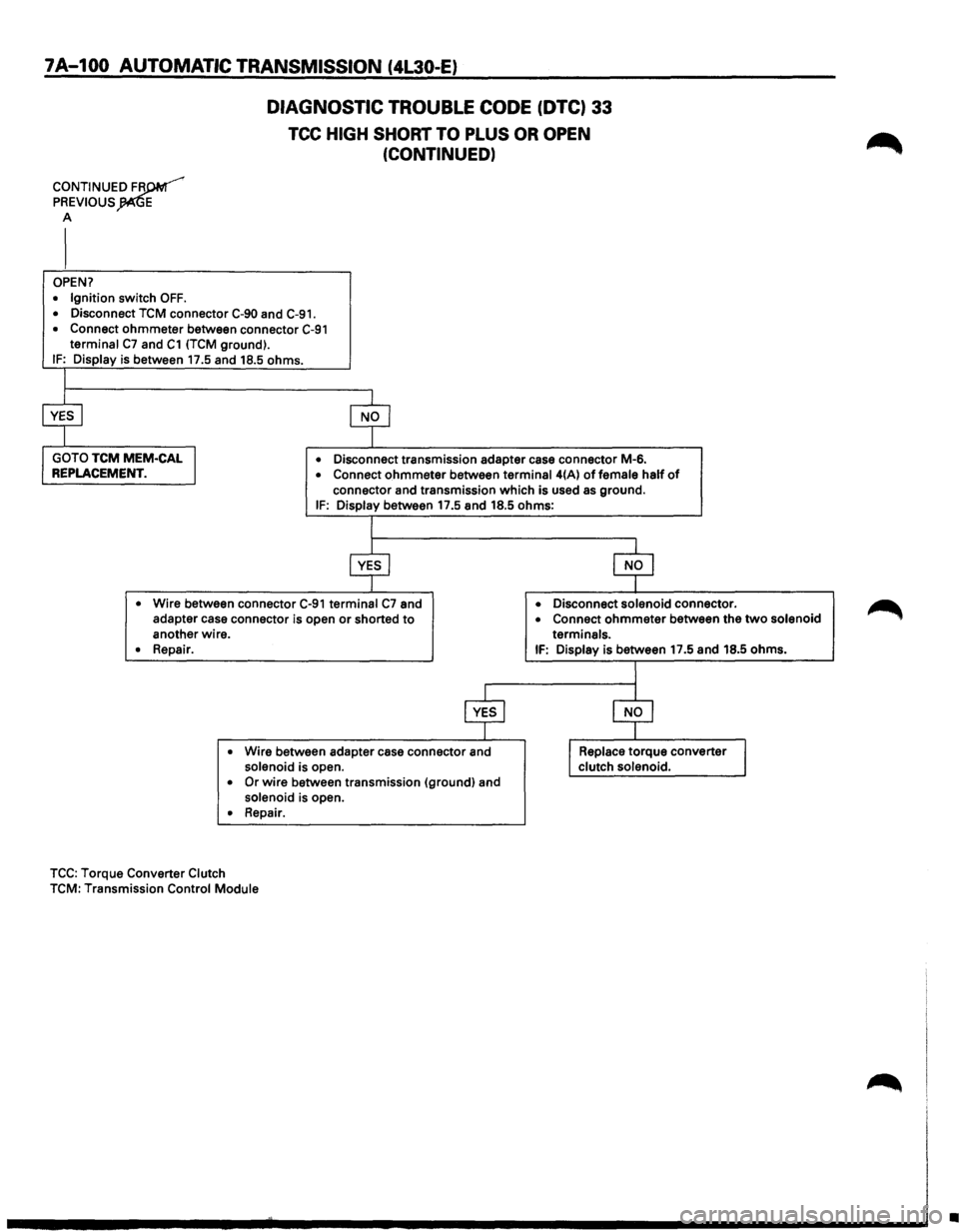
OPEN?
• Ignition switch OFF.
• Disconnect TCM connector C-90 and C-91.
• Connect ohmmeter between connector C-91 terminal C7 and C1 (TCM ground).
IF: Display is between 17.5 and 18.5 ohms.
• Disconnect transmission adapter case connector M-6. • Connect ohmmeter between terminal 4(A) of female half of
connector and transmission which is used as ground. IF: Display between 17.5 and 18.5 ohms:
• Wire between connector C-91 terminal C7 and
adapter case connector is open or shorted to another wire.
• Repair.
• Wire between adapter case connector and solenoid is open. • Or wire between transmission (ground) and
solenoid is open. • Repair.
TCC: Torque Converter Clutch TCM: Transmission Control Module •
Disconnect solenoid connector. • Connect ohmmeter between
the two solenoid
terminals.
IF: Display is between 17.5 and 18.5 ohms.
•
Page 974 of 1928
7A-102 AUTOMATIC TRANSMISSION (4L30-E)
DIAGNOSTIC TROUBLE CODE
(DTC) 34
BAND APPLY SOLENOID SHORT TO GROUND OR OPEN
This DTC flashes the CHECK TRANS indicator and
sets the BACKUP
MODE.
Circuit Description:
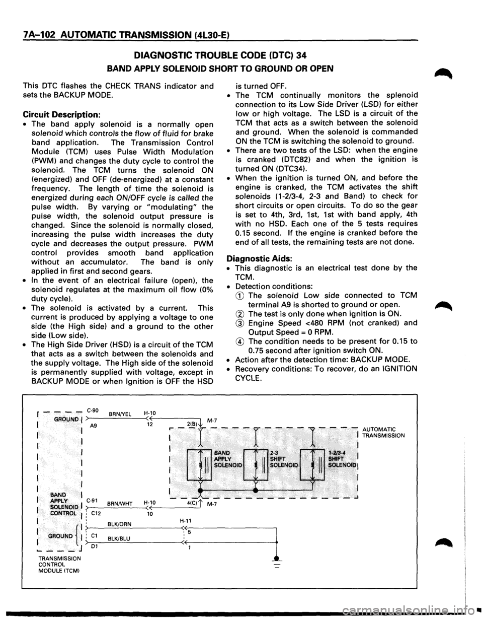
• The band apply solenoid is a normally open
solenoid
which controls the flow of fluid for brake
band
application. The Transmission Control
Module (TCM) uses Pulse Width Modulation
(PWM) and changes the duty cycle to control the
solenoid. The
TCM turns the solenoid ON
(energized) and OFF (de-energized) at a constant
frequency. The length
of time the solenoid is
energized
during each ON/OFF cycle is called the
pulse
width. By varying or "modulating" the
pulse
width, the solenoid output pressure is
changed.
Since the solenoid is normally closed,
increasing the pulse width increases the duty
cycle and decreases the output pressure. PWM
control provides smooth band application
without an accumulator. The band is only
applied in first and second gears.
• In the event of an electrical failure (open), the
solenoid regulates at the
maximum oil flow (0%
duty cycle).
• The solenoid is activated by a current. This
current is produced
by applying a voltage to one
side (the High side) and a
ground to the other
side (low side).
• The High Side Driver (HSD) is a circuit of the TCM
that acts as a switch between the solenoids and
the
supply voltage. The High side of the solenoid
is
permanently supplied with voltage, except in
BACKUP
MODE or when Ignition is OFF the HSD
2{8)\l, M-7
r----C-90 BRN/YEL H-10 ( 12
is turned OFF.
• The TCM continually monitors the splenoid
connection
to its low Side Driver (LSD) for either
low or high voltage. The LSD is a circuit of the
TCM that acts as a switch between the solenoid
and
ground. When the solenoid is commanded
ON the TCM is switching the solenoid to ground.
• There are two tests of the LSD: when the engine
is cranked (DTC82) and
when the ignition is
turned ON (DTC34).
• When the ignition is turned ON, and before the
engine is cranked, the TCM activates the shift
solenoids (1-2/3-4, 2-3 and Band) to check for
short circuits or open circuits. To do so the gear
is set
to 4th, 3rd, 1st, 1st with band apply, 4th
with no HSD. Each one of the 5 tests requires
0.15 second. If the engine is cranked before the
end
of all tests, the remaining tests are not done.
Diagnostic Aids:
• This diagnostic is an electrical test done by the
TCM.
• Detection conditions:
CD The solenoid low side connected to TCM
terminal A9 is shorted to ground or open.
@ The test is only done when ignition is ON.
@ Engine Speed <480 RPM (not cranked) and
Output Speed= 0 RPM.
® The condition needs to be present for 0.15 to
0.75 second after ignition switch ON.
•
Action after the detection time: BACKUP MODE.
•
Recovery conditions: To recover, do an IGNITION
CYCLE.
: --r ----r ----
1-
- -: ~Z[;'~,~~ION
I 1'•1 ~~ If ~!FT . i '· !:
I
I
I
1 ·. SOI:!Noto· R sOLI!lQI,~, . ~ , ~. sOt.ENOiti•J
I ,Ji'Ji ·
· I
I •• ) . I
--~~---------~---~ >--------<
I
I I
BAND APPLY C-91 BRNtWHT H-10
I SOLENOID ( CONTROL : C12 10
I .
: GROUND {
. BLK/ORN . ; C1 BLK/BLU :> 01 ..... ---J
H-11
TRANSMISSION
CONTROL
MODULE (TCM)
•
Page 975 of 1928
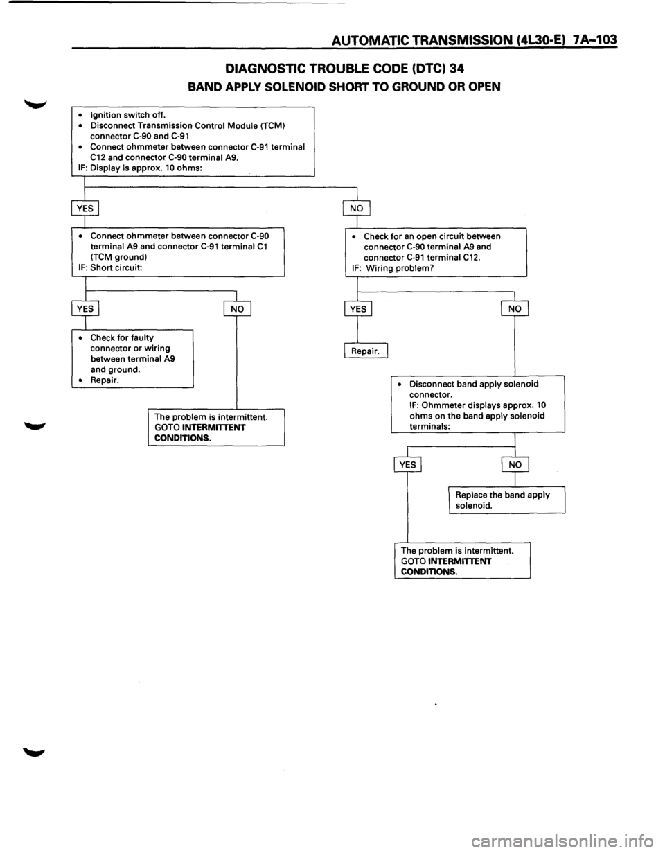
AUTOMATIC TRANSMISSION (4L30-E) 7 A-103
DIAGNOSTIC TROUBLE CODE (DTC) 34
BAND APPLY SOLENOID SHORT TO GROUND OR OPEN
• Ignition switch off. • Disconnect Transmission Control Module (TCM) connector C-90 and C-91
• Connect ohmmeter between connector C-91 terminal C12 and connector C-90 terminal A9. IF: Display is approx. 10 ohms:
• Connect ohmmeter between connector C-90 terminal A9 and connector C-91 terminal C1 (TCM ground)
IF: Short circuit:
• Check for faulty connector or wiring
between terminal A9
and ground.
• Repair.
The
problem is intermittent.
GOTO INTERMITTENT
CONDITIONS.
• Check for an open circuit between
connector C-90 terminal A9 and
connector
C-91 terminal C12. IF: Wiring problem?
•
Disconnect band apply solenoid connector. IF: Ohmmeter displays approx. 10
ohms on the band apply solenoid terminals:
The
problem is intermittent.
GOTO INTERMmENT CONDITIONS.
Page 976 of 1928
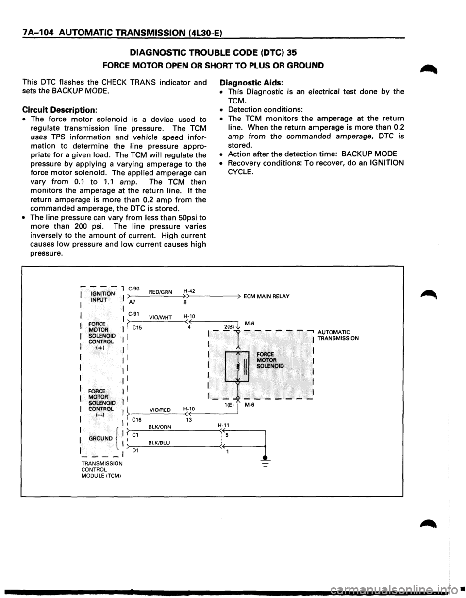
7A-104 AUTOMATIC TRANSMISSION (4L30-E)
DIAGNOSTIC TROUBLE CODE (DTC} 35
FORCE MOTOR OPEN OR SHORT TO PLUS OR GROUND
This DTC flashes the CHECK TRANS indicator and
sets the
BACKUP MODE.
Circuit Description:
• The force motor solenoid is a device used to
regulate transmission line pressure. The TCM
uses
TPS information and vehicle speed infor
mation to determine the line pressure appro
priate
for a given load. The TCM will regulate the
pressure
by applying a varying amperage to the
force
motor solenoid. The applied amperage can
vary from 0.1 to 1.1 amp. The TCM then
monitors the amperage at the return line. If the
return amperage is
more than 0.2 amp from the
commanded amperage, the DTC is stored.
• The line pressure can vary from less than 50psi to
more than 200 psi. The line pressure varies
inversely
to the amount of current. High current
causes
low pressure and low current causes high
pressure.
Diagnostic Aids:
• This Diagnostic is an electrical test done by the
TCM.
• Detection conditions:
• The TCM monitors the amperage at the return
line. When the return amperage is
more than 0.2
amp from the commanded amperage, DTC is
stored.
• Action after the detection time: BACKUP MODE
•
Recovery conditions: To recover, do an IGNITION
CYCLE.
----1 C-90 I IGNITION I >----R_ED_..:./G..:...R_N_4H'>--4
-2----4 ECM MAIN RELAY I INPUT A7
8
I I C-91 H-10 I VIO;WHT >~----'-----~<~<------~ I FORCE I I -C15 4
2(6) l M-6
MOTOR I--1------...., AUTOMATIC I SOLENOID I I T s ON
CONTROL I I RAN MISSI
I I+J Jl I I I FORCE
I : : til: :g~~H> :
I II I
I FORCE II I
I
MOTOR I I I - --- - --- - -SOLENOID HEJ t M-6 I CONTROL I I VIO/RED H-10 I f-) >·-----------(<(~------~ I l : C16 13 BLK/ORN H-11 1 {'f~c-1-=~~----~~.·~
1
I GAOUNO I >-1 __ ___cB:..:l::.c:K/c.::.B=..:LU:..__ ________ -<
I 01
----' TRANSMISSION
CONTROL
MODULE
(TCM)
•
Page 977 of 1928
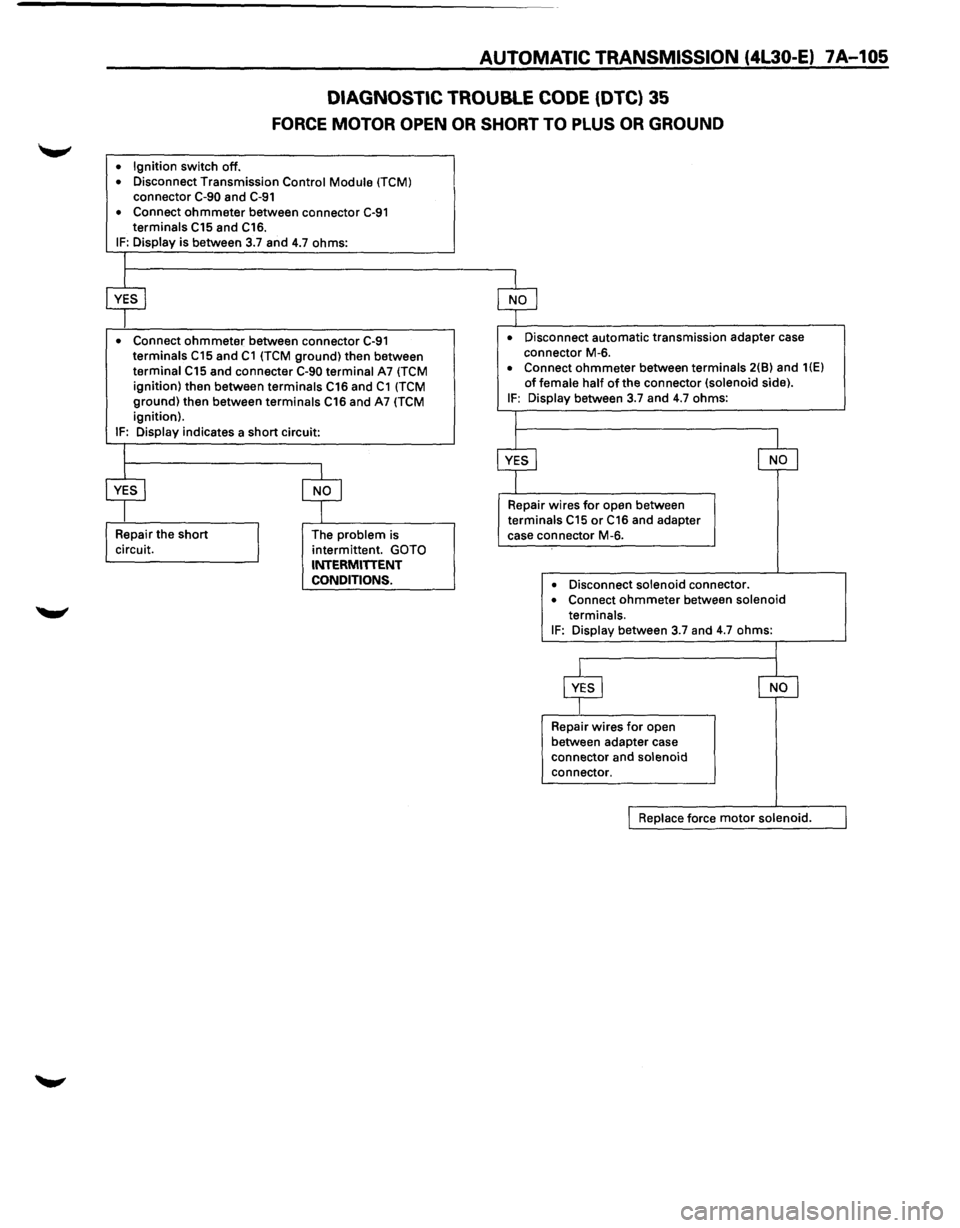
AUTOMATIC TRANSMISSION (4l30-E) 7A-105
DIAGNOSTIC
TROUBLE CODE (DTC) 35
FORCE MOTOR OPEN OR SHORT TO PLUS OR GROUND
• Ignition switch off.
• Disconnect Transmission Control Module (TCM) connector C-90 and C-91
• Connect ohmmeter between connector C-91 terminals C15 and C16. IF: Display is between 3.7 and 4.7 ohms:
• Connect ohmmeter between connector C-91 terminals C15 and C1 {TCM ground) then between
terminal C15 and connecter C-90 terminal A7 (TCM ignition) then between terminals C16 and C1 (TCM ground) then between terminals C16 and A7 (TCM ignition).
IF: Display indicates a short circuit:
The
problem is
intermittent. GOTO INTERMITIENT
CONDITIONS.
• Disconnect automatic transmission adapter case
connector M-6.
• Connect ohmmeter between terminals 2(8) and 1(E)
of female half of the connector (solenoid side). IF: Display between 3.7 and 4.7 ohms:
Repair wires
for open between terminals C15 or C16 and adapter
case connector M-6.
• Disconnect solenoid connector. • Connect ohmmeter between solenoid
terminals.
IF: Display between 3.7 and 4.7 ohms:
Repair wires
for open
between adapter case
connector and
solenoid connector.
Replace force motor solenoid.
Page 978 of 1928
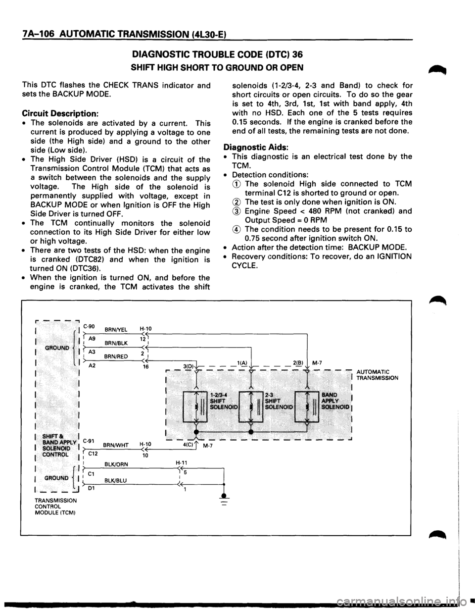
7A-106 AUTOMATIC TRANSMISSION (4l30-E)
DIAGNOSTIC TROUBLE CODE (DTC) 36
SHIFT HIGH SHORT TO GROUND OR OPEN
This DTC flashes the CHECK TRANS indicator and
sets the BACKUP
MODE.
Circuit Description:
• The solenoids are activated by a current. This
current is produced
by applying a voltage to one
side (the High side) and a
ground to the other
side (low side).
• The High Side Driver (HSD) is a circuit of the
Transmission
Control Module (TCM) that acts as
a switch between the solenoids and the supply
voltage. The High side of the solenoid is
permanently supplied with voltage, except in
BACKUP
MODE or when Ignition is OFF the High
Side Driver is turned OFF.
• The TCM continually monitors the solenoid
connection to its High Side Driver for either low
or high voltage.
•
There are two tests of the HSD: when the engine
is cranked (DTC82) and
when the ignition is
turned ON (DTC36).
• When the ignition is turned ON, and before the
engine is cranked, the TCM activates the
shift
BRN/YEL H-10 (
BRN/BLK 12 I
BRN/RED ;: ( 16
solenoids ( 1-2/3-4, 2-3 and Band) to check for
short circuits or open circuits. To do so the gear
is set
to 4th, 3rd, 1st, 1st with band apply, 4th
with no HSD. Each one of the 5 tests requires
0.15 seconds. If the engine is cranked before the
end
of all tests, the remaining tests are not done.
Diagnostic Aids:
• This diagnostic is an electrical test done by the
TCM.
• Detection conditions:
CD The solenoid High side connected to TCM
terminal C12 is shorted to ground or open.
@ The test is only done when ignition is ON.
@ Engine1 Speed < 480 RPM (not cranked) and
Output Speed = 0 RPM
@ The condition needs to be present for 0.15 to
0.75 second after ignition switch ON.
•
Action after the detection time: BACKUP MODE.
•
Recovery Gonditions: To recover, do an IGNITION
CYCLE.
•
Page 979 of 1928
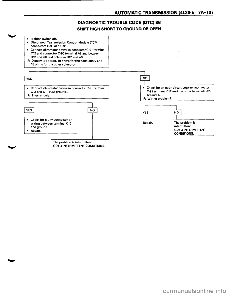
AUTOMATIC TRANSMISSION (4L30-E) 7A-107
DIAGNOSTIC TROUBLE CODE (DTC) 36
SHIFT HIGH SHORT TO GROUND OR OPEN
• Ignition switch off .
• Disconnect Transmission Control Module (TCM)
connectors C-90 and C-91.
• Connect ohmmeter between connector C-91 terminal C12 and connector C-90 terminal A2 and between
C12 and A3 and between C12 and A9. IF: Display is approx. 10 ohms for the band apply and 18 ohms for the other solenoids:
I
$ $
• Connect ohmmeter between connector C-91 terminal • Check for an open circuit between connector
C12 and C1 (TCM ground). C-91 terminal C12 and the other terminals A2,
IF: Short circuit: A3
and A9.
I IF: Wiring problem?
I
$ 8
$ $ • Check for faulty connector or wiring between terminal C12 I Repair. I The problem is
and ground. intermittent.
• Repair
. GOTO INTERMmENT
CONDITIONS.
I The problem is intermittent. GOTO INTERMITTENT CONDITIONS.
Page 980 of 1928
7A-108 AUTOMATIC TRANSMISSION (4l30·E)
DIAGNOSTIC TROUBLE CODE (DTC) 37
TORQUE MANAGEMENT SERIAL LINE FAULTY
This DTC flashes the CHECK TRANS indicator and
sets the
BACKUP MODE.
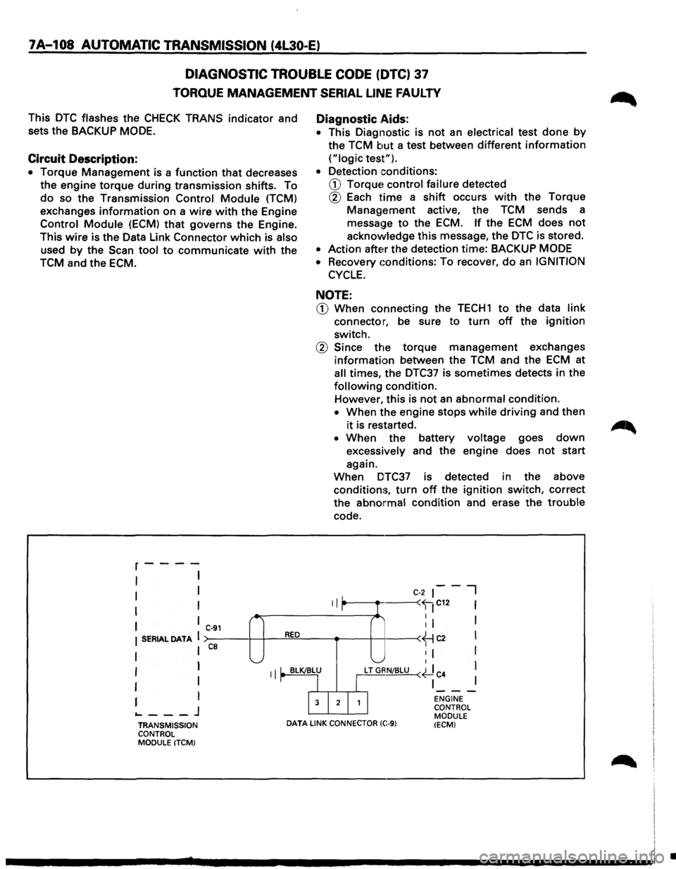
Circuit Description:
• Torque Management is a function that decreases
the engine
torque during transmission shifts. To
do so the Transmission Control Module (TCM)
exchanges
information on a wire with the Engine
Control Module (ECM) that governs the Engine.
This
wire is the Data Link Connector which is also
used by the Scan tool to communicate with the
TCM and the ECM.
r----
I I
I I
I I
I ,_
I C-91
I SERIAL DATA I RED
ca
I I '-._....;
Diagnostic .Aids:
• This
Diagnostic is not an electrical test done by
the TCM but a test between different information
("logic test").
•
Detection conditions:
CD Torque~ control failure detected
® Each time a shift occurs with the Torque
Management active, the TCM sends a
message
to the ECM. If the ECM does not
acknowledge this message, the DTC is stored.
• Action after the detection time: BACKUP MODE
• Recovery Gonditions: To recover, do an IGNITION
CYCLE.
NOTE:
CD When connecting the TECH1 to the data link
connector, be sure to turn off the ignition
switch.
® Since the torque management exchanges
information between the TCM and the ECM at
all times, the DTC37 is sometimes detects in the
following condition.
However,
this is not an abnormal condition.
• When the engine stops while driving and then
it is restarted.
• When the battery voltage goes down
excessively and the engine does not start
again.
When DTC37 is detected in the above
conditions,
turn off the ignition switch, correct
the
abnormal condition and erase the trouble
code.
II L
C-2 ~--I
r I ----
I I I '-" t
I I II' BLK/BLU
LT GRN/BLU (~ C
4 I
I I
r I I
I
I
I 3 I 2 I 1 I
---I ENGINE
... ---J CONTROL
MODULE
TRANSMISSION
DATA LINK CONNECTOR (C:-9) (ECM) CONTROL
MODULE (TCM)
•