ISUZU TROOPER 1995 Owner's Manual
Manufacturer: ISUZU, Model Year: 1995, Model line: TROOPER, Model: ISUZU TROOPER 1995Pages: 1928
Page 21 of 1928
FLUID LEVEL CHECK
A fluid loss in any system (except windshield
washer) may indicate a problem. Repair the system
at once.
Engine
oil level -Check level and add if
necessary. The best time to check the engine oil
level is
when the oil is warm. After stopping the
engine with the vehicle on a level surface, wait a
few minutes for the oil to drain back to the oil pan.
Pull
out the oil level indicator (dipstick). Wipe it
clean and push the oil level indicator back down all
the
way. Pull out the oil level indicator, keeping the
tip down, and look at the oil level on it.
Add oil, if needed, to keep the oil level above
the
"ADD" mark and between the "ADD" and
"FULL" marks in the operating range area. Avoid
overfilling the engine since this may cause engine
damage. Push
the oil level indicator back down all
the
way after taking the reading.
If you check the oil level when the oil is cold, do
not run the engine first. The cold oil will not drain
back
to the pan fast enough to give a true oil level.
Engine coolant level and condition -Check
engine coolant level in the coolant reservoir and
add engine
coolant if necessary. Inspect the engine
coolant and replace it if dirty or rusty.
Windshield washer fluid level -Check washer
fluid level in reservoir and add if necessary.
Power steering system reservoir level-Check
and keep at
proper level.
Brake master cylinder reservoir level -Check
fluid. Keep fluid at proper level. A low fluid level
can indicate
worn disc brake pads which may need
to be serviced.
Hydraulic clutch system -Check fluid l~vel in
the reservoir.
Add fluid as required.
Battery fluid level -Check fluid level in the
battery.
FLUID LEAK CHECK
Check for fuel, water, oil or other fluid leaks by
looking at the surface beneath the vehicle after it
has been parked for a while. Water dripping from
the air conditioning system after use is normal. If
you notice gasoline fumes or fluid at any time,
locate the source and correct it at once.
ENGINE OIL AND OIL FILTER
REPLACEMENT
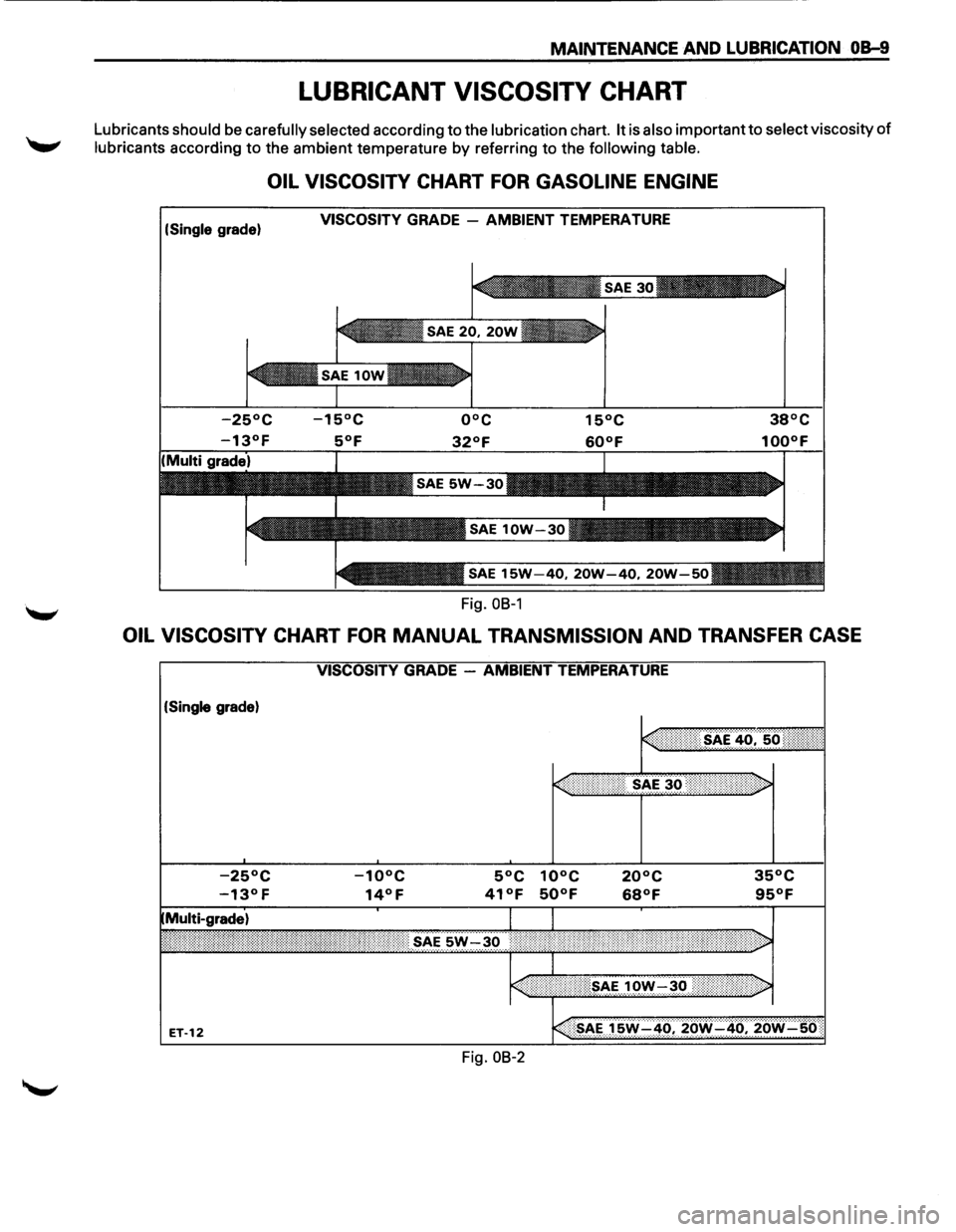
Always use API SE, SF, SG, SH or ILSAC GF-1
quality oils of the proper viscosity.
When choosing an oil, consider the range of
temperatures the car will be operated in before the
next oil change. Then, select the recommended oil
viscosity
from the chart (Fig. OB-1).
Always change the oil and the oil filter as soon as
possible after driving in a dust storm.
MAINTENANCE AND LUBRICATION OB-5
ENGINE COOLING SYSTEM INSPECTION
Inspect coolant/anti-freeze. If coolant is dirty or
rusty, drain, flush and refill with new coolant. Keep
coolant at the proper mixture for proper freeze
protection,
corrosion inhibitor level and best engine
operating temperature.
Inspect hoses and replace if
cracked, swollen or deteriorated. Tighten hose
clamps if equipped with screw-type clamps. Clean
outside of radiator and air conditioning condenser.
Wash
filler cap and neck. To help ensure proper
operation, a pressure test of both the cooling
system and cap is also recommended.
EXHAUST SYSTEM INSPECTION
Visually inspect the exhaust pipes, muffler, heat
shields and hangers
for cracks, deterioration, or
damage.
Be alert to any changes in the sound of the exhaust
system
or any smell of fumes. These are signs the
system may be leaking or overheating. Repair the
system at once,
if these conditions exist. (See also
"Engine Exhaust Gas Safety" and "Three Way
Catalytic Converter" in Owner's manual.)
FUEL CAP, FUEL LINES, AND FUEL TANK
INSPECTION
Inspect the fuel tank, the fuel cap and the fuel lines
every
60,000 miles (96,000 km) for damage which
could cause leakage.
Inspect the fuel cap and the gasket for correct sealing
and physical damage. Replace any damaged parts.
DRIVE BELT INSPECTION
Check the belts driving the steering oil pump, the air
conditioning compressor, and the generator
for
cracks, fraying, wear, and correct tension every 30,000
miles (48,000 km). Adjust or replace as necessary.
WHEEL ALIGNMENT, BALANCE AND
TIRES OPERATION
Uneven or abnormal tire wear, or a pull right or left
on a straight and level road may show the need for
a wheel alignment. A vibration of the steering
wheel or seat at normal highway speeds means a
wheel balancing is needed. Check tire pressure
when the tires are "cold" (include the spare).
Maintain pressure as shown in the tire placard,
which is located on the driver's door lock pillar.
STEERING SYSTEM OPERATION
Be alert for any changes in steering action. An
inspection
or service is needed when the steering
wheel is harder
to turn or has too much free play, or
if there are unusual sounds when turning or parking.
Page 22 of 1928
OB-6 MAINTENANCE AND LUBRICATION
BRAKE SYSTEMS OPERATION
Watch for the "BRAKE" light coming on. Other
signs of possible brake trouble are such things as
repeated pulling to one side when braking, unusual
sounds
when braking or between brake
applications,
or increased brake pedal travel. If you
note one of these conditions, repair the system at
once.
For convenience, the
following should be done
when wheels are removed for rotation: Inspect lines
and hoses
for proper hookup, bindings, leaks, crack,
chafing etc.
Inspect disc brake pads for wear and
rotors
for surface condition.
Inspect other brake parts, including parking brake
drums, linings etc., at the same time. Check parking
brake adjustment.
Inspect brakes more often if habit or
conditions
result in frequent braking.
PARKING BRAKE AND TRANSMISSION
PARK MECHANISM OPERATION
Park on a fairly steep hill and hold the vehicle with
the parking brake only. This checks holding ability.
On
automatic transmission vehicles, shifting from
"P" position to the other positions cannot be made
unless
the brake pedal is depressed when the key
switch is in
"ON" position or the engine running.
WARNING
•
Before checking starter safety switch
operation below,
be sure to have enough
room around the
vehicle. Then firmly apply
both the parking brake and the regular brake.
Do not
use the accelerator pedal. If the engine
starts, be ready
to turn off the key promptly.
Take these precautions because the vehicle
could move
without warning and possibly
cause personal injury
or property damage.
STARTER SAFETY SWITCH OPERATION
(AUTOMATIC TRANSMISSION)
Check by trying to start the engine in each gear
while setting the parking brake and the foot brake.
The starter
should crank only in "P" (Park) or "N"
(Neutral).
STARTER SAFETY SWITCH OPERATION
(MANUAL TRANSMISSION)
To check, place the shift lever in "Neutral", push
the clutch pedal halfway and try to start. The starter
should not crank. The starter should crank only
when the clutch pedal is fully depressed.
ACCELERATOR LINKAGE LUBRICATION
Lubricate the accelerator pedal fulcrum pin with
chassis grease.
STEERING AND SUSPENSION
INSPECTION
Inspect front and rear suspension and steering
system
for damaged, loose or missing parts or signs
of wear. Inspect power steering lines and hoses for
proper hookup, binding, leaks, cracks, chafing, etc.
BODY AND CHASSIS LUBRICATION
Lubricate the key lock cylinders, the hood latch, the
hood and door hinges, the door check link, the
parking cable guides,
the underbody contact points,
and the linkage.
PROPELLER SHAFT INSPECTION AND
LUBRICATION
Lubricate sliding yoke and universal joints with
grease containing MOS2 (disulfide molybdenum
type grease) at the interval shown in the
Maintenance Schedule. Check for play in normal
direction of rotation of sliding yoke and universal
joints. Also check
propeller shaft flange-to-pinion
bolts for proper torque of 63 N·m (46 lb·ft) for front
and rear propeller shaft.
AUTOMATIC TRANSMISSION FLUID
INSPECTION
Check the lubricant level every 7,500 miles (12,000
km) and add lubricant
if necessary.
Under harsh operating conditions, such as constant
driving in heavy city traffic during
hot weather, or in
hilly or mountainous terrain, change the transmission
fluid and service the
sump filter after every 20,000
miles (32,000 km) of operation.
AUTO CRUISE CONTROL INSPECTION
Check to see if the clearance between cruise link and
accelerator is normal. Also check that the vacuum
hoses are routed and connected properly.
CLUTCH LINES AND HOSES INSPECTION
Check lines and hoses for proper attachment,
binding, leaks, cracks, chafing, deterioration, etc.
Any questionable parts should be replaced or
repaired at once. When abrasion or wear is evident
on lines or hoses, the cause must be corrected.
..
Page 23 of 1928
CLUTCH CONTROL LUBRICATION
Lubricate the clutch pedal bushing, the clevis pin,
and
pedal spring every 15,000 miles (24,000 km) or 6
months.
If a squeaking noise arises from around the bushing
or the clevis pin at the clutch pedal arm when the
clutch pedal is depressed, lubricate them.
CLUTCH PEDAL FREE PLAY INSPECTION
Note the clutch pedal free play. It should be 5 -15
mm (0.2 -0.6 in). Adjust clutch control when there is
little or no free play.
ACCELERATOR LINKAGE INSPECTION
Inspect for interference, binding, and damaged or
missing parts. Check accelerator pedal for smooth
operation and even
pedal effort. Replace parts as
needed.
MAINTENANCE AND LUBRICATION OB-7
Page 24 of 1928
OB-8 MAINTENANCE AND LUBRICATION
RECOMMENDED FLUIDS AND LUBRICANTS
USAGE FLUID/LUBRICANT
Engine API SE, SF, SG, SH or ILSAC GF-1 Engine oil
(See oil
chart on the following page for
proper viscosity)
Engine
coolant Mixture of water and good quality ethylene glycol
base type antifreeze.
Brake system
DOT-3 hydraulic brake fluid.
Power steering system
DEXRON® 11-E Automatic transmission fluid.
Automatic transmission DEXRON®-III Automatic transmission fluid.
Manual transmission
Engine oil
(See oil
chart on following page for proper viscosity)
Rear
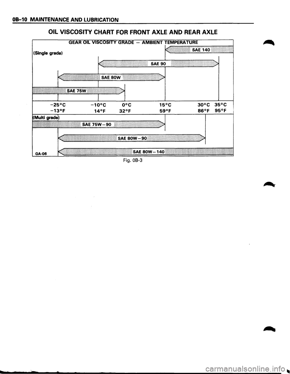
axle and front axle GL-5 gear lubricant (Standard differential)
GL-5 Limited slip differential gear lubricant (If
equipped with optional limited slip differential)
(See oil
chart in this section for proper viscosity)
Clutch system
a. Pivot points Engine oil
b. Clutch fork joint Chassis grease
c. Master cylinder DOT-3 hydraulic brake fluid
Hood latch assembly
a. Pivots and spring anchor
Engine oil
b. Release pawl Chassis grease
Hood and
door hinges
Engine oil
Chassis lubrication Chassis greae
Parking brake
cables Chassis grease
Front wheel bearings Wheel bearing grease
Free
Wheeling hubs (Automatic) Specified grease (available as service parts)
Propeller shafts
Sliding yoke and Universal joint Grease containing MoS2 or multipurpose type
grease NLGI No.2
Body
door hinge pins and linkage, fuel door hinge,
Engine oil
rear compartment lid hinges
Windshield washer solvent Washer fluid
Key lock cylinder Engine oil
Accelerator linkage
Chassis grease
Page 25 of 1928
MAINTENANCE AND LUBRICATION 08-9
LUBRICANT VISCOSITY CHART
Lubricants should be carefully selected according to the lubrication chart. It is also important to select viscosity of
lubricants according to the ambient temperature by referring to the following table.
OIL VISCOSITY CHART FOR GASOLINE ENGINE
(Single grade) VISCOSITY GRADE -AMBIENT TEMPERATURE
Fig.
OB-1
OIL VISCOSITY CHART FOR MANUAL TRANSMISSION AND TRANSFER CASE
(Single grade)
Fig.
08-2
Page 26 of 1928
OB-10 MAINTENANCE AND LUBRICATION
OIL VISCOSITY CHART FOR FRONT AXLE AND REAR AXLE
(Single grade)
15°C 30°C 35°C
59°F 86°F 95°F
GA-06
Fig. OB-3
Page 27 of 1928
,
MAINTENANCE AND LUBRICATION OB-11
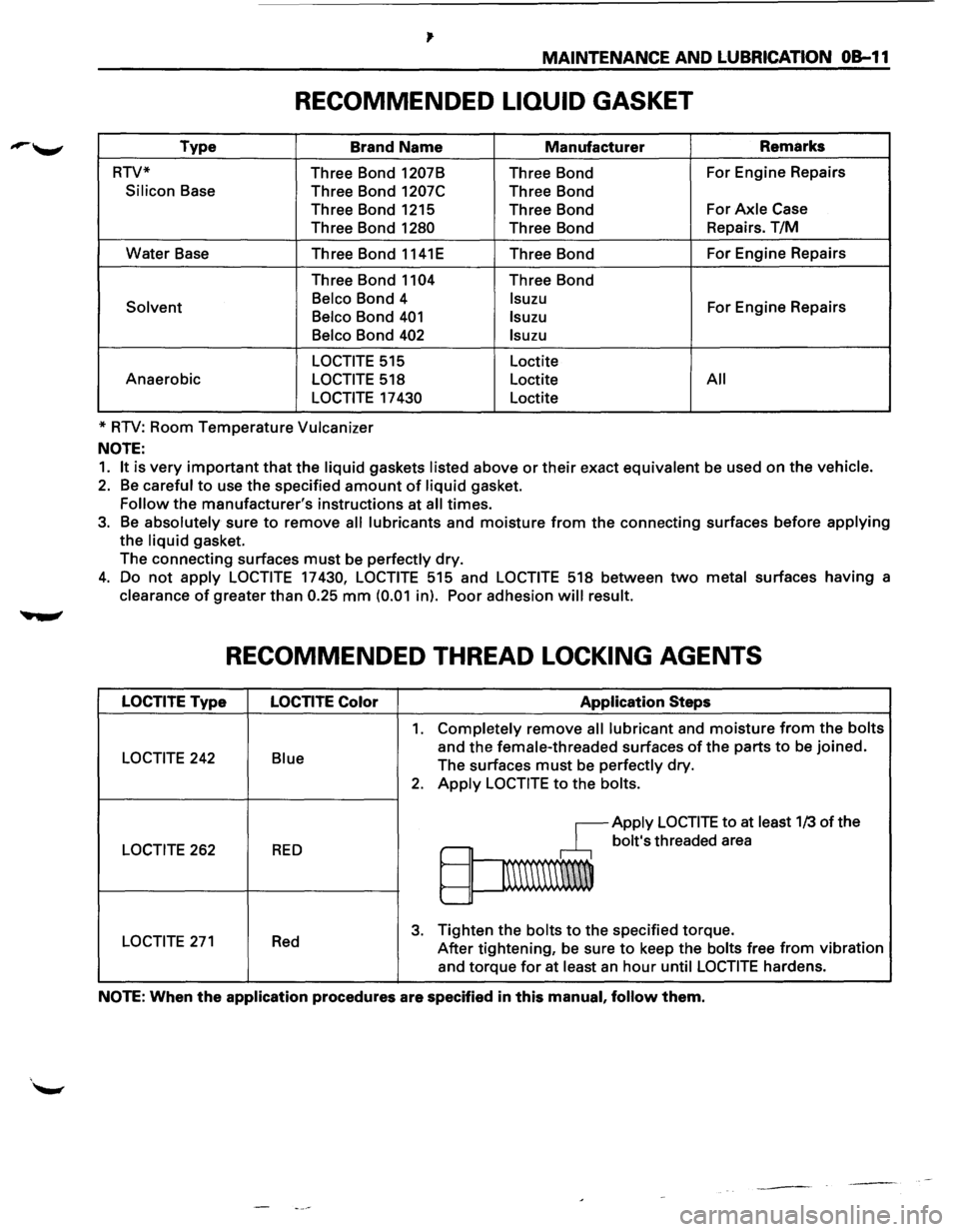
RECOMMENDED LIQUID GASKET
Type Brand Name Manufacturer Remarks
RTV* Three Bond
1207B Three Bond For
Engine Repairs
Silicon Base
Three Bond 1207C Three Bond
Three Bond 1215 Three Bond For
Axle Case
Three Bond
1280 Three Bond Repairs.
T/M
Water Base
Three Bond 1141E Three Bond For
Engine Repairs
Three Bond
1104 Three Bond
Solvent Belco Bond
4 lsuzu For Engine Repairs Belco Bond 401 lsuzu
Belco
Bond 402 lsuzu
LOCTITE
515 Loctite
Anaerobic
LOCTITE 518 Loctite All
LOCTITE
17 430 Loctite
*
RTV: Room Temperature Vulcanizer
NOTE:
1. It is very important that the liquid gaskets listed above or their exact equivalent be used on the vehicle.
2. Be careful to use the specified amount of liquid gasket.
Follow the manufacturer's instructions at all times.
3. Be absolutely sure to remove all lubricants and moisture from the connecting surfaces before applying
the liquid gasket.
The connecting surfaces
must be perfectly dry.
4. Do not apply LOCTITE 17430, LOCTITE 515 and LOCTITE 518 between two metal surfaces having a
clearance
of greater than 0.25 mm (0.01 in). Poor adhesion will result.
RECOMMENDED THREAD LOCKING AGENTS
LOCTITE Type LOCTITE Color Application Steps
1. Completely remove all lubricant and moisture from the bolts
LOCTITE 242 Blue and the female-threaded surfaces of the parts to be joined.
The surfaces
must be perfectly dry.
2. Apply LOCTITE to the bolts.
~Apply LOCTITE to at least 1/3 of the
LOCTITE 262 RED ,.-bolt's threaded area
~
1\\\\\\\W
'--
LOCTITE 271 Red 3. Tighten the bolts to the specified torque.
After tightening, be sure
to keep the bolts free from vibration
and torque
for at least an hour until LOCTITE hardens.
NOTE: When the application procedures are specified in this manual, follow them.
Page 28 of 1928
OB-12 MAINTENANCE AND LUBRICATION
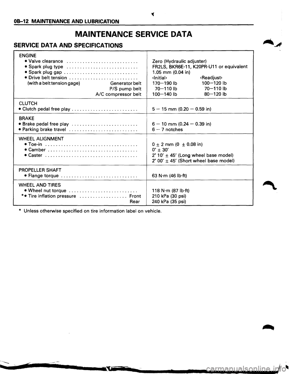
MAINTENANCE SERVICE DATA
SERVICE DATA AND SPECIFICATIONS
ENGINE
• Valve clearance I o o I I I 0 0 0 I 0 o o o o o I 0 o o o 0 0 o o o o Zero (Hydraulic adjuster)
• Spark plug type I I o 0 I o 0 I I I 0 o o o I 0 I o o 0 0 0 o o 0 0 0 FR2LS, BKR6E-1 1, K20PR-U11 or equivalent
•
Spark plug gap ............................ 1.05 mm (0.04 in)
• Drive belt tension ..........................
(with a belttension gage)
Generator belt 170-190 lb 100-120 lb
PIS
pump belt 70-110 lb 70-110 lb
A/C compressor belt 100-140 lb 80-120 lb
CLUTCH
• Clutch pedal free play ......................... 5 -15 mm (0.20 -0.59 in)
BRAKE
• Brake pedal free play o o o o o o o o 0 0 o o o o o 0 0 o o 0 I o o o o 6 -10 mm (0.24 -0.39 in)
• Parking brake travel ••••••••••••••••••\
•• 0 ••••• 6-7 notches
WHEEL
ALIGNMENT
•
Toe-in 0 0 o o 0 0 I 0 0 o o o o 0 0 0 0 o o o o I 0 0 o o 0 0 o o o o 0 I 0 0 ± 2 mm (0 ± 0.08 in)
• Camber .................................. oo ± 30'
•
Caster o o o 0 0 0 0 o o o o o o I 0 0 o o o o 0 0 o o o o 0 o o o o o 0 0 o 2° 1 0' ± 45' (Long wheel base model)
2° 00' ± 45' (Short wheel base model)
PROPELLER SHAFT
• Flange torque ••••••••••••••••••\
•• 0' ••• 0 ••• 63 N·m (46 lb·ft)
WHEEL AND TIRES
• Wheel nut torque o o o o 0 0 o o o o o o o o o o o I o o o o 0 0 0 o 118 N·m (87 lb·ft)
* • Tire inflation pressure •••••••••••••• 0 ••• Front 21 0 kPa (30 psi)
Rear
240 kPa (35 psi)
* Unless otherwise specified on tire information label on vehicle.
~~-.... ¢ .............. .-I ~ -.,~iii~-..--. ....... 2 ........ -. .................. ~~ - I
Page 29 of 1928
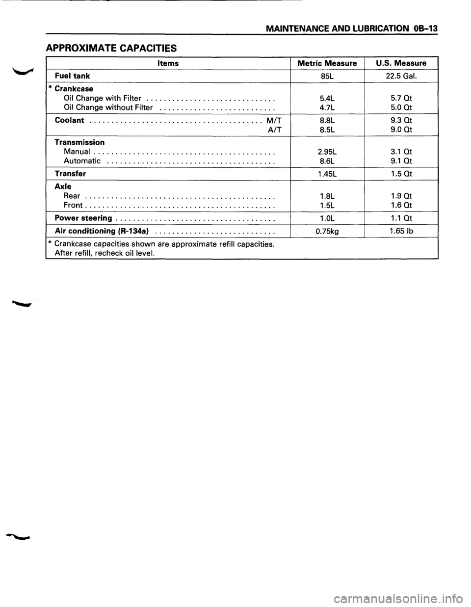
MAINTENANCE AND LUBRICATION OB-13
APPROXIMATE CAPACITIES
Items Metric Measure U.S. Measure
Fuel tank 85L 22.5 Gal.
*Crankcase
Oil Change with Filter .............................. 5.4L 5.7 at
Oil Change without Filter ••••••••••••••••••\
0 •••• 0 ••• 4.7L
5.0 at
Coolant ........................................ MIT 8.8L 9.3 at
A/T 8.5L 9.0 at
Transmission
Manual
.......................................... 2.95L 3.1 at
Automatic ••••••••••••••••••\
•• 0 •••• 0 0 0 ••••••••••• 8.6L 9.1 at
Transfer
1.45L 1.5 at
Axle
Rear o o o 0
0 0 0 0 0 0 0 0 0 0 0 0 0 0 0 0 I 0 0 0 o o o o o o o 0 0 0 0 0 0 0 0 0 0 0 o o 1.8L 1.9 at
Front ........................................ ~ ... 1.5L 1.6 at
Power steering ••• 0 ••••••••• 0 ••••••••••••••••••\
0 •••• 1.0L 1.1 at
Air conditioning (R-134a) o o 0
0 0 0 0 0 0 0 0 I 0 0 0 0 0 o o 0 o 0 0 0 0 0 0 0 0.75kg 1.651b
* Crankcase capacities shown are approximate refill capacities.
After
refill, recheck oil level.
Page 30 of 1928
MEMO