ISUZU TROOPER 1995 Owner's Guide
Manufacturer: ISUZU, Model Year: 1995, Model line: TROOPER, Model: ISUZU TROOPER 1995Pages: 1928
Page 31 of 1928
HEATING AND VENTILATION 1A-1
HEATING AND AIR CONDITIONING
CONTENTS
Heating and Ventilation .................................................... Section 1A
Air Conditioning . . . . . . . . . . . . . . . . . . . . . . . . . . . . . . . . . . . . . . . . . . . . . . . . . . . . . . . . . . Section 1 B
Compressor Overhaul. . .
. . . . . . . . . . . . . . . . . . . . . . . . . . . . . . . . . . . . . . . . . . . . . . . . . . . Section 1 D
SECTION 1A
HEATING AND VENTILATION
CONTENTS
General Description .................... 1A-2 On-Vehicle Service ..................... 1A-11
Heater . . . . . . . . . . . . . . . . . . . . . . . . . . . . . . 1
A-2 Heater Unit . . . . . . . . . . . . . . . . . . . . . . . . . 1A-11
Control Lever Assembly . . . . . . . . . . . . . . . 1 A-3 Heater Core and/or Mode Door ......... 1A-12
Ventilation .......................... 1A-3 Heater Mode Control Link Unit ......... 1A-14
Air Select Knob . . . . . . . . . . . . . . . . . . . . . . 1 A-4 Heater Temperature Control Link Unit ... 1A-15
Air Source Select Lever ............... 1A-4 Blower Assembly .................... 1A-16
Fan Control Knob .................... 1A-4 Blower Link Unit and/or Mode Door . . . . 1A-17
Temperature Control Knob ............ 1A-4 Blower Motor ....................... 1A-18
Wiring Diagram . . . . . . . . . . . . . . . . . . . . . . . . 1A-5
Rear Heater Duct, Defroster Nozzle
Diagnosis ............................. 1A-6 and Ventilation Duct ............... 1A-19
.. # Heating Cycle Diagnosis ............... 1A-6 Center and/or Driver Side Vent ......... 1A-20
Fan Control Lever (Fan Switch) Control Lever Assembly
Diagnosis . . . . . . . . . . . . . . . . . . . . . . . . . 1 A-7 and/or Control Cables .............. 1A-21
Individual Inspection ................. 1A-10 Control Panel Illumination Bulb ........ 1A-23
Resistor ............................ 1A-23
Page 32 of 1928
1A-2 HEATING AND VENTILATION
GENERAL DESCRIPTION
HEATER
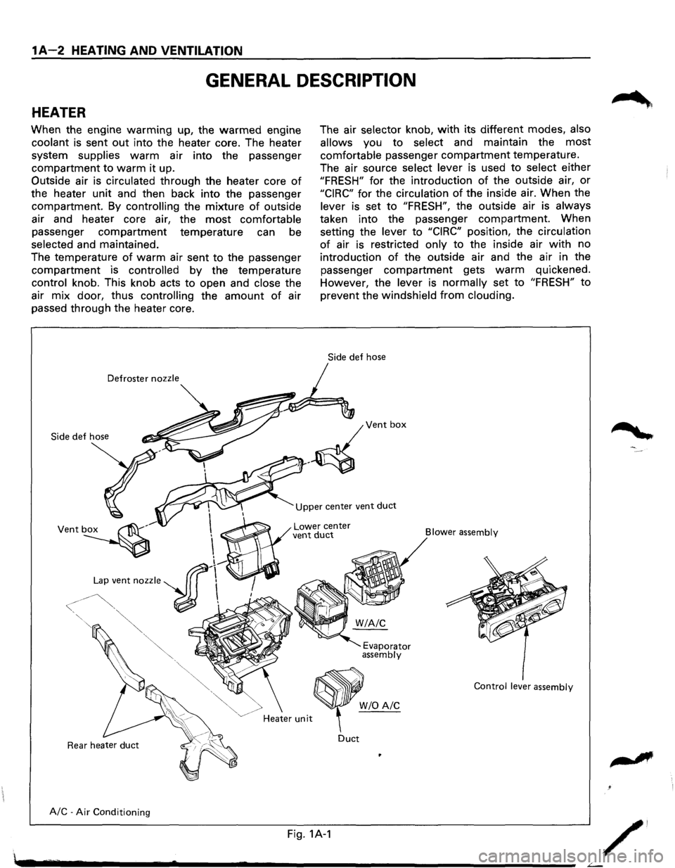
When the engine warming up, the warmed engine
coolant is sent out into the heater core. The heater
system
supplies warm air into the passenger
compartment to warm it up.
Outside air is
circulated through the heater core of
the heater unit and then back into the passenger
compartment. By
controlling the mixture of outside
air and heater core air, the
most comfortable
passenger compartment temperature can be
selected and maintained.
The temperature
of warm air sent to the passenger
compartment is controlled by the temperature
control knob. This knob acts to open and close the
air
mix door, thus controlling the amount of air
passed through the heater core.
Defroster nozzle
Side
def hose
The air selector knob, with its different modes, also
allows
you to select and maintain the most
comfortable passenger compartment temperature.
The air source
select lever is used to select either
"FRESH" for the introduction of the outside air, or
"CIRC" for the circulation of the inside air. When the
lever is set to "FRESH", the outside air is always
taken into the passenger compartment. When
setting the
lever to "CIRC" position, the circulation
of air is restricted only to the inside air with no
introduction
of the outside air and the air in the
passenger
compartment gets warm quickened.
However, the
lever is normally set to "FRESH" to
prevent the windshield from clouding.
Upper center vent duct
A/C-Air Conditioning Lower
center vent duct
<
Heater unit
Duct
Fig. 1A-1
Blower
assembly
Evaporator assembly
Control lever assembly
W/0 A/C
/'
Page 33 of 1928
CONTROL LEVER ASSEMBL V
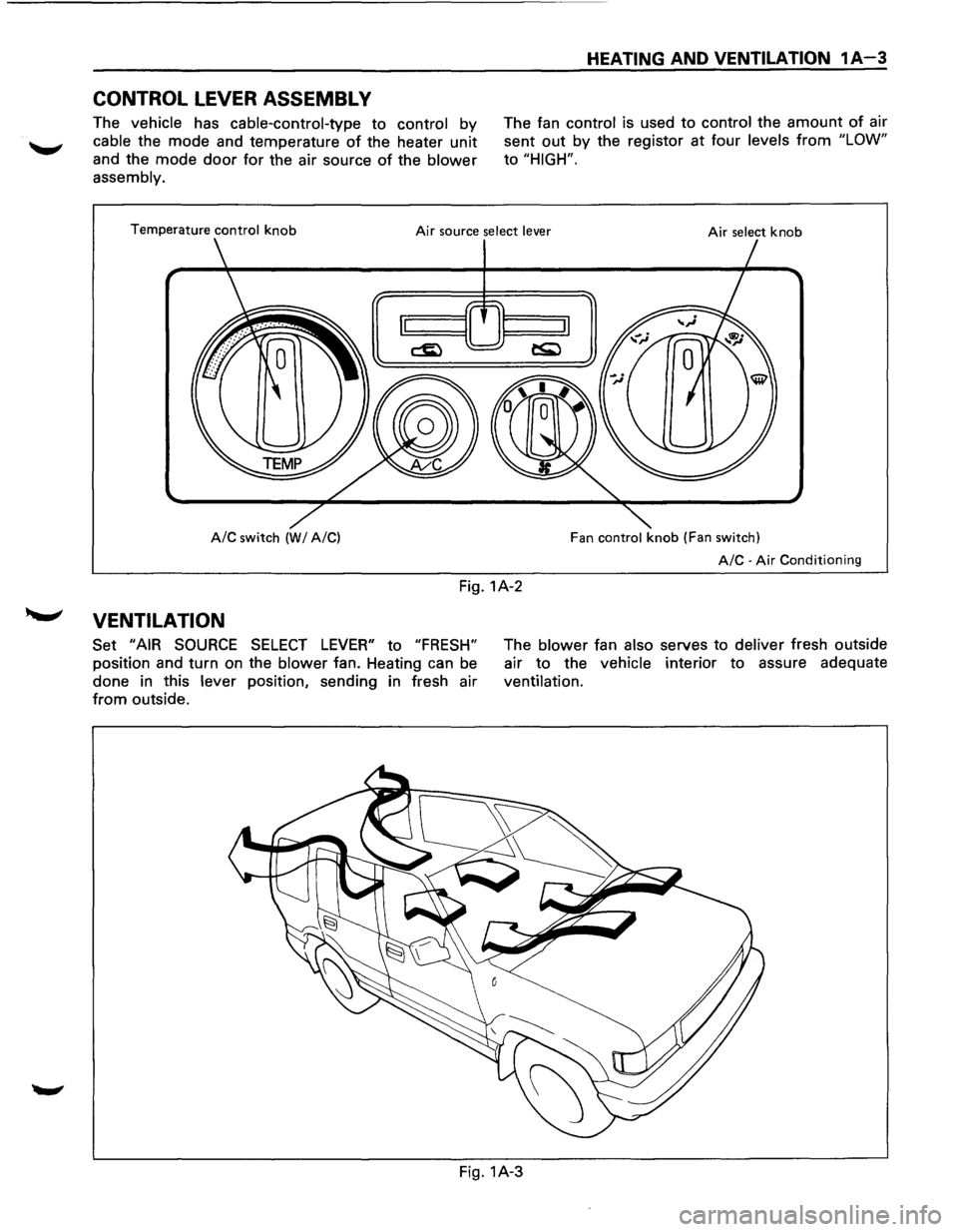
The vehicle has cable-control-type to control by
cable the mode and temperature of the heater unit
and the mode door for the air source of the blower
assembly.
HEATING AND VENTILATION 1A-3
The fan control is used to control the amount of air
sent
out by the registor at four levels from "LOW"
to "HIGH".
Temperature control knob Air source select lever Air select knob
A/C switch (WI A/C) Fan control knob (Fan switch)
A/C-Air Conditioning
Fig. 1A-2
,__,.. VENTILATION
Set "AIR SOURCE SELECT LEVER" to "FRESH"
position and turn on the blower fan. Heating can be
done in this
lever position, sending in fresh air
from outside. The
blower fan also serves
to deliver fresh outside
air
to the vehicle interior to assure adequate
ventilation.
Fig. 1A-3
Page 34 of 1928
1A-4 HEATING AND VENTILATION
AIR SELECT KNOB
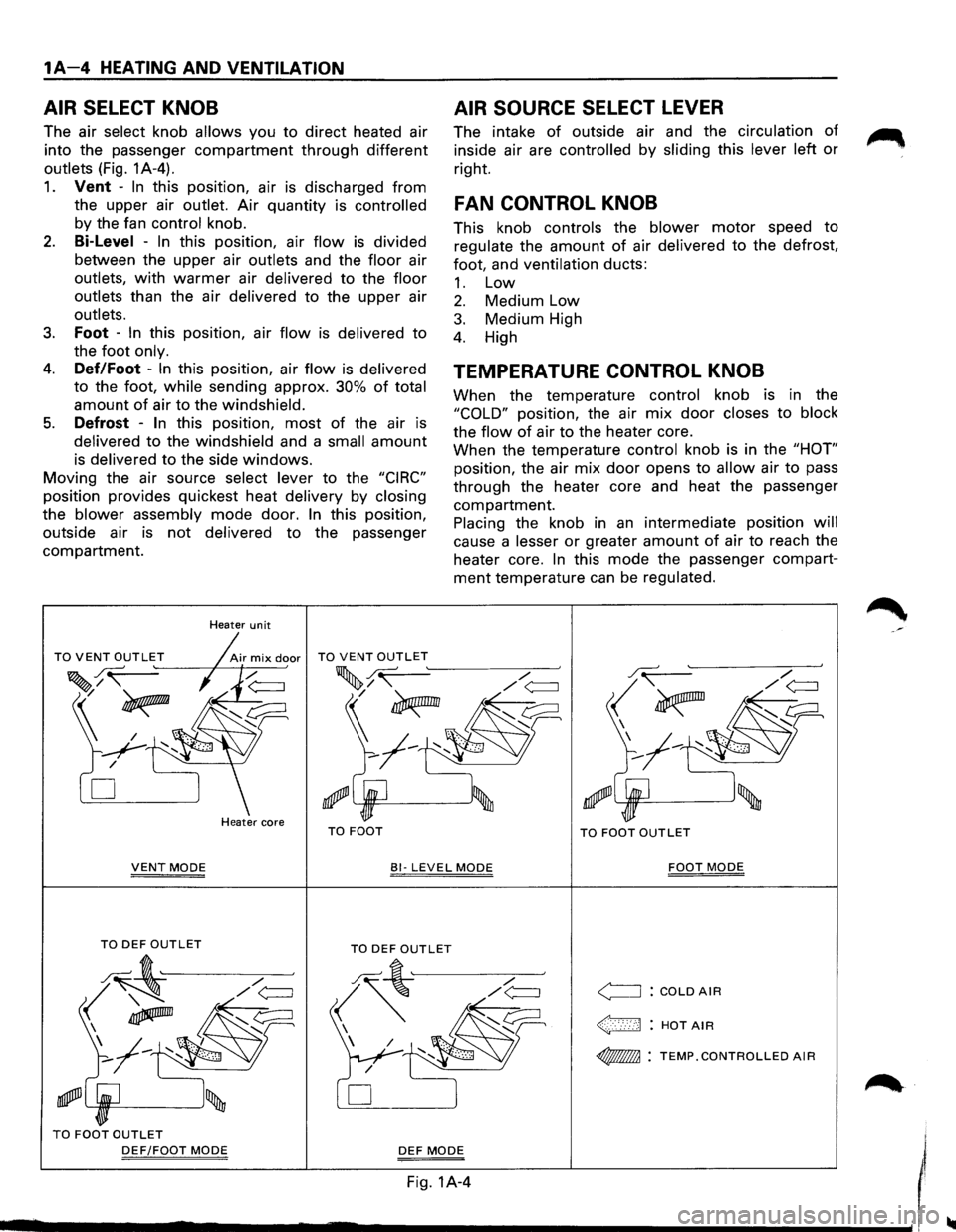
The air select knob allows you to direct heated air
into the passenger
compartment through different
outlets (Fig. 1A-4).
1. Vent -In this position, air is discharged from
the upper air
outlet. Air quantity is controlled
by the fan control knob.
2. Bi-Level -In this position, air flow is divided
between the upper air
outlets and the floor air
outlets, with warmer air delivered to the floor
outlets
than the air delivered to the upper air
outlets.
3. Foot -In this position, air flow is delivered to
the foot only.
4. Def/Foot -In this position, air flow is delivered
to the foot, while sending approx. 30% of total
amount of air to the windshield.
5. Defrost -In this position, most of the air is
delivered to the windshield and a small amount
is delivered to the side windows.
Moving the air source select lever to the "CIRC"
position provides quickest heat delivery by closing
the blower assembly mode door. In this position,
outside air
is not delivered to the passenger
compartment.
Heater unit
D
Heater core TO FOOT
AIR SOURCE SELECT LEVER
The intake of outside air and the circulation of
inside air are controlled by sliding this lever left or
right.
FAN CONTROL KNOB
This knob controls the blower motor speed to
regulate the amount of air delivered to the defrost,
foot, and
ventilation ducts:
1. Low
2. Medium Low
3. Medium High
4. High
TEMPERATURE CONTROL KNOB
When the temperature control knob is in the
"COLD" position, the air mix door closes to block
the flow of air to the heater core.
When the temperature
control knob is in the "HOT"
position, the air mix door opens to allow air to pass
through the heater core and heat the passenger
compartment.
Placing the knob in an intermediate position will
cause a lesser or greater amount of air to reach the
heater core.
In this mode the passenger compart
ment temperature can be regulated.
.r.( /
<_;~~
'--'R!I=---_____.J'
TO FOOT OUTLET
VENT MODE 81-LEVEL MODE FOOT MODE
TO FOOT OUTLET
DEF/FOOT MODE DEF MODE
Fig. 1A-4
<==:J : COLD AIR
~: HOTAIR
~ : TEMP.CONTROLLED AIR
I ........................................................................\
...... ------------------~1
Page 35 of 1928
~~[II] BODY ENG. FRAME
HEATING AND VENTILATION 1A-5
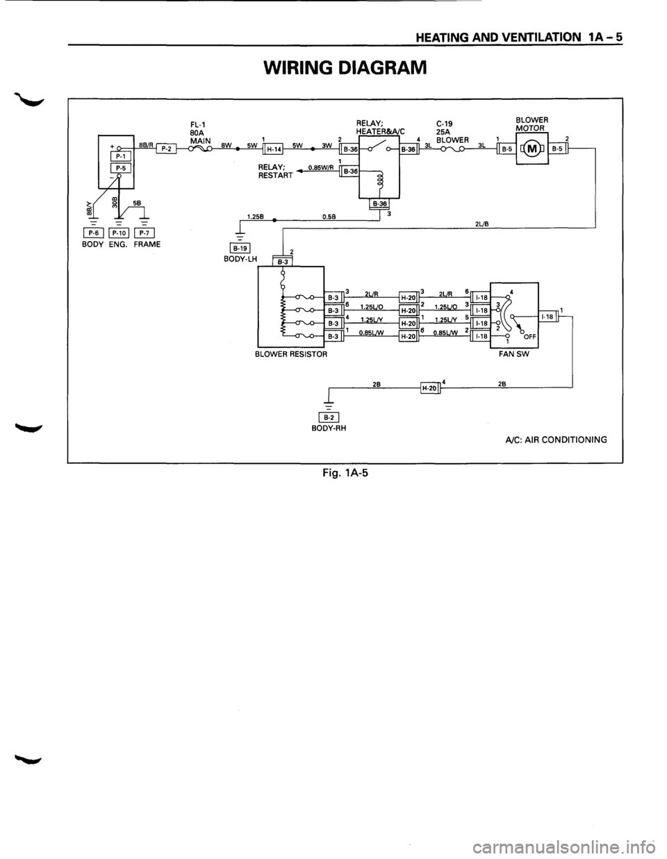
WIRING DIAGRAM
aw
RELAY;
RESTART
1.258
I 8-1el BODY-LH
0.58 2LJ8
BLOWER RESISTOR
r------'2::.::8:,__ __ _,H-201~4 ____ __,2""8 _____ __,
~ BODY-RH
AJC: AIR CONDITIONING
Fig. 1A-5
Page 36 of 1928
1A-6 HEATING AND VENTILATION
DIAGNOSIS
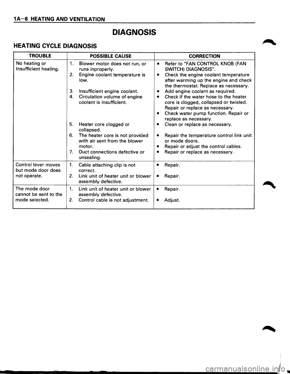
HEATING CYCLE DIAGNOSIS
TROUBLE POSSIBLE CAUSE CORRECTION
No heating or 1. Blower motor does not run, or • Refer to "FAN CONTROL KNOB (FAN
Insufficient heating.
runs inproperly. SWITCH) DIAGNOSIS".
2. Engine coolant temperature is • Check the engine coolant temperature
low. after warming up the engine and check
the thermostat.
Replace as necessary.
3. Insufficient engine coolant. • Add engine coolant as required .
4. Circulation volume of engine • Check if the water hose to the heater
coolant is insufficient. core is clogged, collapsed or twisted.
Repair
or replace as necessary.
• Check water pump function. Repair or
replace as necessary.
5. Heater core clogged or • Clean or replace as necessary.
collapsed.
6. The heater core is not provided • Repair the temperature control link unit
with air sent from the blower or mode doors.
motor.
• Repair or adjust the control cables.
7. Duct connections defective or • Repair or replace as necessary.
unsealing.
Control lever
moves 1. Cable attaching clip is not • Repair.
but
mode door does correct.
not operate. 2. Link unit of heater unit or blower • Repair.
assembly defective.
The
mode door 1. Link unit of heater unit or blower • Repair.
cannot
be sent to the assembly defective.
mode
selected. 2. Control cable is not adjustment. • Adjust.
_______ __... ..... ..._ ____________ (
Page 37 of 1928
FAN CONTROL LEVER (FAN SWITCH)
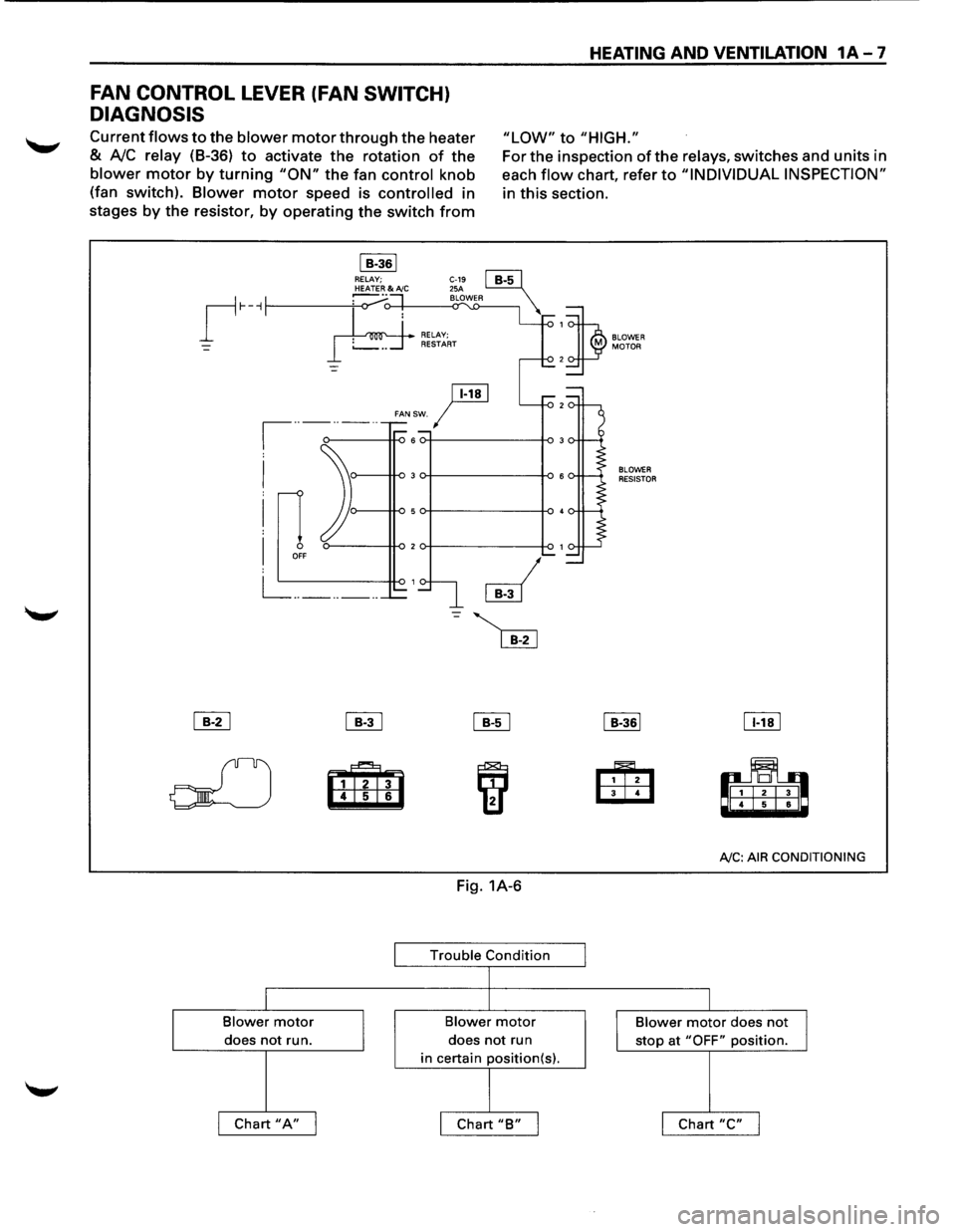
DIAGNOSIS
HEATING AND VENTILATION 1A-7
Current flows to the blower motor through the heater
& A!C relay (8-36) to activate the rotation of the
blower motor by turning "ON" the fan control knob
(fan switch).
Blower motor speed is controlled in
stages
by the resistor, by operating the switch from
"LOW" to "HIGH."
I B-361 RELAY;
ji!!J
For the inspection of the relays, switches and units in
each
flow chart, refer to "INDIVIDUAL INSPECTION"
in this section.
1
)
BLOWER MOTOR 2
r-··-··-··
FANSW. I
I
I
I
0 OFF
L= _______ _
~ ~
olJ m 6
I
Blower motor
I does not run.
I Chart "A" I
~
iif1
Fig. 1A-6
Trouble Condition
I
l
Blower motor
does not run
in certain position(s).
I
I Chart "B" I I
BLOWER RESISTOR
I B-361
Eili3 4
IT!!]
rl! 6
AJC: AIR
CONDITIONING
I
Blower motor does not
J stop at "OFF" position.
I Chart "C" I
Page 38 of 1928
1A-8 HEATING AND VENTILATION
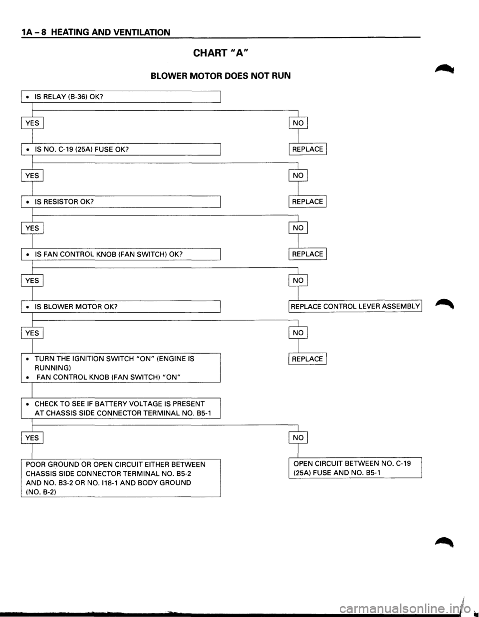
CHART II A"
BLOWER MOTOR DOES NOT RUN
• TURN THE IGNITION SWITCH "ON" (ENGINE IS
RUNNING)
•
FAN CONTROL KNOB (FAN SWITCH) "ON"
• CHECK TO SEE IF BATTERY VOLTAGE IS PRESENT
AT CHASSIS SIDE CONNECTOR TERMINAL NO. B5-1
POOR GROUND OR OPEN CIRCUIT EITHER BETWEEN
CHASSIS SIDE CONNECTOR TERMINAL NO. B5-2
AND NO. B3-2 OR NO. 118-1 AND BODY GROUND
(NO. B-2) (25A)
FUSE AND NO. B5-1
Page 39 of 1928
HEATING AND VENTILATION 1A-...9
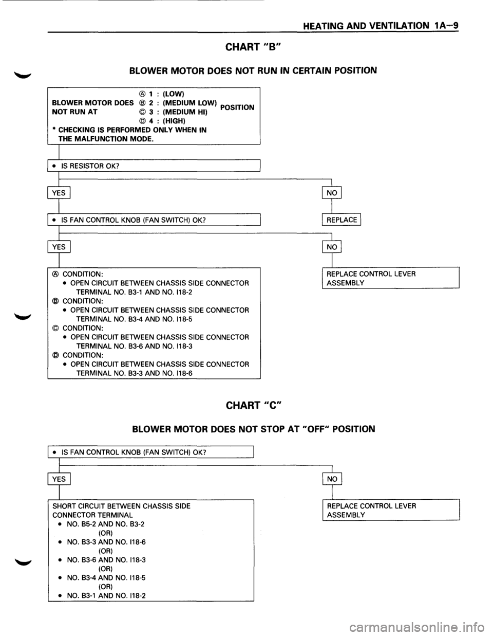
CHART "B"
BLOWER MOTOR DOES NOT RUN IN CERTAIN POSITION
® 1 :(LOW)
BLOWER MOTOR DOES @ 2 : (MEDIUM LOW) POSITION NOT RUN AT © 3 : (MEDIUM HI)
@ 4: (HIGH)
* CHECKING IS PERFORMED ONLY WHEN IN
THE MALFUNCTION MODE.
I
• IS RESISTOR OK?
I
~ ~
• IS FAN CONTROL KNOB (FAN SWITCH) OK? I REPLACE I
I
~ ~
® CONDITION: I REPLACE CONTROL LEVER
• OPEN CIRCUIT BETWEEN CHASSIS SIDE CONNECTOR ASSEMBLY
TERMINAL NO.
B3-1 AND NO. 118-2
@CONDITION:
• OPEN CIRCUIT BETWEEN CHASSIS SIDE CONNECTOR
TERMINAL NO.
B3-4 AND NO. 118-5
©CONDITION:
• OPEN CIRCUIT BETWEEN CHASSIS SIDE CONNECTOR
TERMINAL NO.
B3-6 AND NO. 118-3
@ CONDITION:
• OPEN CIRCUIT
BETWEEN CHASSIS SIDE CONNECTOR
TERMINAL NO.
B3-3 AND NO. 118-6
CHART "C"
BLOWER MOTOR DOES NOT STOP AT "OFF" POSITION
• IS FAN CONTROL KNOB (FAN SWITCH) OK?
I
SHORT CIRCUIT BETWEEN CHASSIS SIDE
CONNECTOR TERMINAL
• NO.
B5-2 AND NO. B3-2
(OR)
• NO. B3-3 AND NO. 118-6
(OR)
• NO. B3-6 AND NO. 118-3
(OR)
• NO. B3-4 AND NO. 118-5
(OR)
• NO. B3-1 AND NO. 118-2
I
REPLACE CONTROL LEVER
ASSEMBLY
I
I
Page 40 of 1928
1A-10 HEATING AND VENTILATION
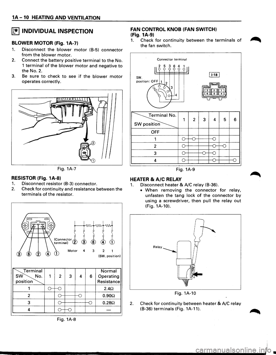
~ INDIVIDUAL INSPECTION
BLOWER MOTOR (Fig. 1A-7)
1. Disconnect the blower motor (B-5) connector
from the blower motor.
2. Connect the battery positive terminal to the No.
1 terminal of the blower motor and negative to
the No.2.
3. Be sure to check to see if the blower motor
operates correctly.
Fig. 1A-7
RESISTOR (Fig. 1A-8)
1. Disconnect resistor (B-3) connector.
2. Check for continuity and resistance between the
terminals of the resistor.
Motor 4 3 2
(SW. position)
Terminal Normal
SW No.
2 3 4 6 Operating
position Resistance
1 2.4Q
2 0.90Q
3 0.28Q
4
Fig. 1A-8
FAN CONTROL KNOB (FAN SWITCH)
(Fig. 1A-9)
1. Check for continuity between the terminals of
the fan switch.
Connector terminal
2 3 4 5 6
OFF
1
2
3
4
Fig. 1A-9
HEATER & A/C RELAY
1. Disconnect heater & A!C relay (B-36).
• When removing the connector for relay,
unfasten the tang lock of the connector by
using a screwdriver, then pull the relay out
(Fig. 1A-10).
Fig. 1A-10
2. Check for continuity between heater & A!C relay
(B-36) terminals (Fig. 1A-11).
~
•