ISUZU TROOPER 1995 Service Manual
Manufacturer: ISUZU, Model Year: 1995, Model line: TROOPER, Model: ISUZU TROOPER 1995Pages: 1928
Page 41 of 1928
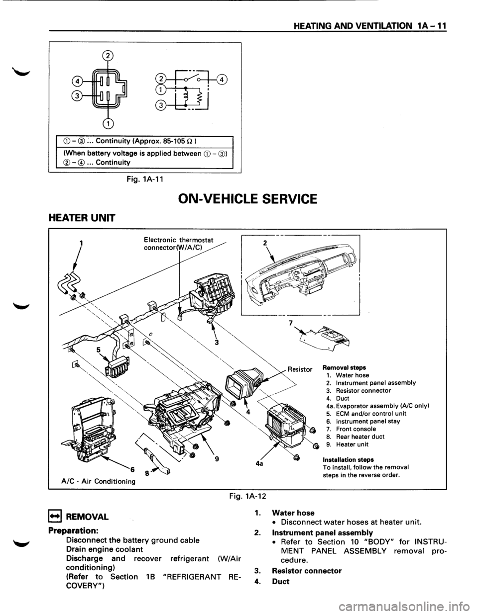
CD-@: .. Continuity (Approx. 85-105 n l
(When battery
voltage is applied between CD-@)
®-@ ... Continuity
Fig. 1A-11
HEATING AND VENTILATION 1A -11
ON-VEHICLE SERVICE
HEATER UNIT
A/C -Air Conditioning
Electronic thermostat
connector(W I A/C)
Removal steps 1. Water hose 2. Instrument panel assembly
3. Resistor connector
4. Duct 4a. Evaporator assembly (AJC only)
5. ECM and/or control unit 6. Instrument panel stay 7. Front console 8. Rear heater duct 9. Heater unit
Installation steps
To
install, follow the removal
steps in the reverse order.
Fig. 1A-12
1••1 REMOVAL
Preparation:
Disconnect the battery ground cable
Drain engine coolant
Discharge and recover refrigerant (W/Air
conditioning)
(Refer to Section 1 B "REFRIGERANT RE
COVERY")
1. Water hose
• Disconnect water hoses at heater unit.
2.
Instrument panel assembly
• Refer to Section 10 "BODY" for INSTRU
MENT PANEL ASSEMBLY removal pro
cedure.
3. Resistor
connector
4. Duct
Page 42 of 1928
1A ";" 12 HEATING AND VENTILATION
4a. Evaporator assembly
• Refer to Section 1 B "AIR CONDITIONING" for
Evaporator Assembly removal procedure.
5. ECM and/or control unit
• Do not disconnect ECM and control unit
connectors.
6. Instrument panel stay
7. Front console
8. Rear heater duct
9. Heater unit
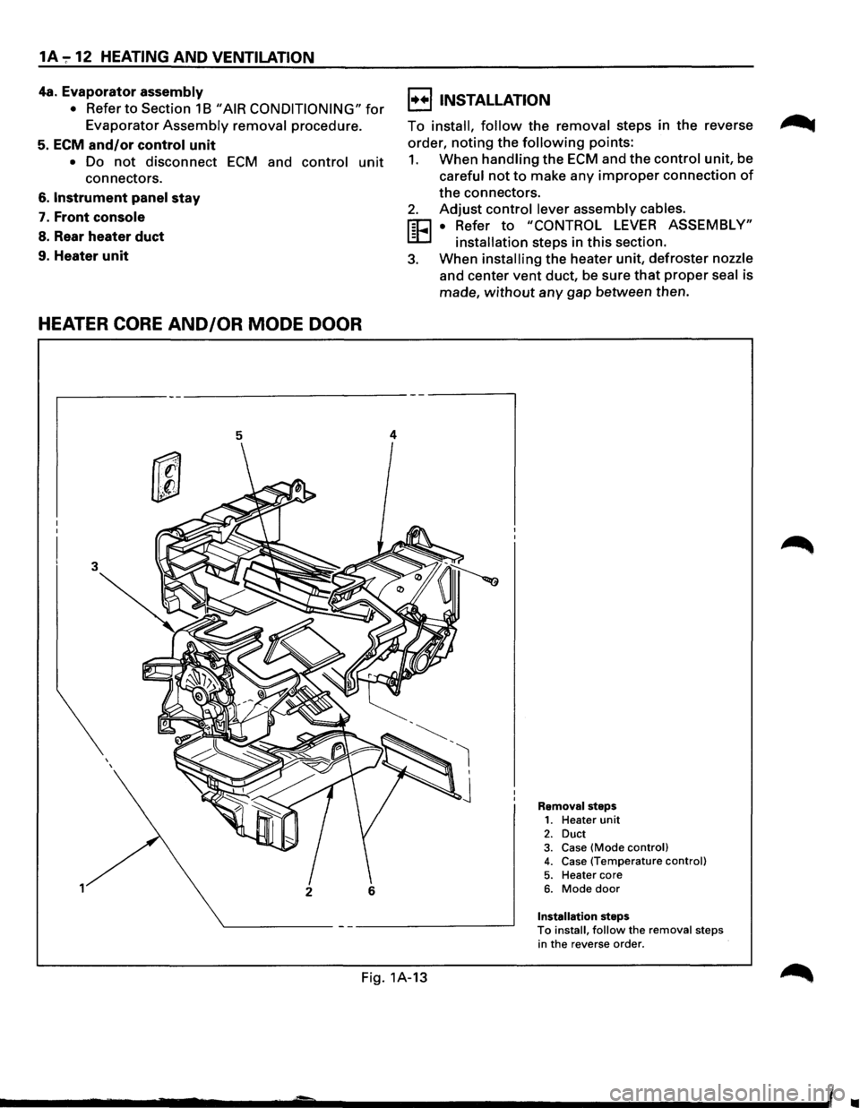
HEATER CORE AND/OR MODE DOOR
3
1
5
2 6
4
I••! INSTALLATION
To install, follow the removal steps in the reverse
order,
noting the following points:
1. When handling the ECM and the control unit, be
careful not to make any improper connection of
the connectors.
2. Adjust control lever assembly cables.
FEI • Refer to "CONTROL LEVER ASSEMBLY"
-installation steps in this section.
3. When installing the heater unit, defroster nozzle
and center vent duct, be sure that proper seal is
made,
without any gap between then.
Removal steps 1. Heater unit 2. Duct 3. Case (Mode control) 4. Case (Temperature control)
5. Heater core 6. Mode door
Installation steps To install, follow the removal steps
in the reverse order.
Fig. 1A-13
..
Page 43 of 1928
1••1 REMOVAL
Preparation:
Disconnect the battery ground cable
Drain engine coolant
1. Heaterunit
• Refer to "HEATER UNIT" removal procedure
in
this section.
2. Duct
3. Case (Mode control)
• Do not remove link unit at this step.
4. Case (Temperature control)
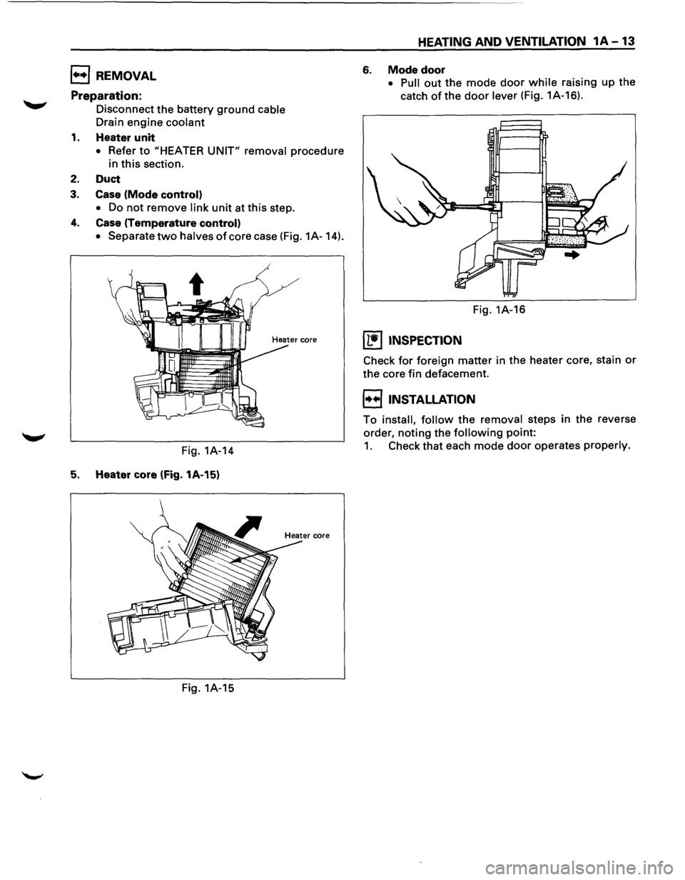
• Separate two halves of core case (Fig. 1A-14).
Fig. 1A-14
5. Heater core (Fig. 1A-15)
Fig. 1A-15
HEATING AND VENTILATION 1A-13
6. Mode door
• Pull out the mode door while raising up the
catch
of the door lever (Fig. 1A-16).
Fig. 1A-16
(b!] INSPECTION
Check for foreign matter in the heater core, stain or
the core fin defacement.
l••liNSTALLATION
To install, follow the removal steps in the reverse
order,
noting the following point:
1. Check that each mode door operates properly.
Page 44 of 1928
1A-14 HEATING AND VENTILATION
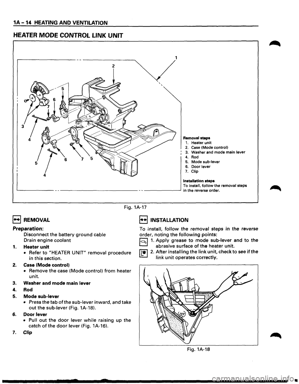
HEATER MODE CONTROL LINK UNIT
2 1
Removal
steps 1. Heater unit 2. Case (Mode control)
3. Washer and mode main lever
4. Rod 5. Mode sub-lever 6. Door lever 7. Clip
Installation
steps
To install, follow the removal steps --------' in the reverse order.
Fig. 1A-17
1••1 REMOVAL
Preparation:
Disconnect the battery ground cable
Drain engine coolant
1. Heater unit
• Refer to "HEATER UNIT" removal procedure
in
this section.
2. Case (Mode control)
•
Remove the case (Mode control) from heater
unit.
3. Washer and mode main lever
4. Rod
5. Mode sub-lever
•
Press the tab of the sub-lever inward, and take
out the sub-lever (Fig. 1A-18).
6. Door lever
• Pull
out the door lever while raising up the
catch
of the door lever (Fig. 1A-16).
7. Clip
I••! INSTALLATION
To install, follow the removal steps in the reverse
order, noting the following points:
1~1 1. Apply grease to mode sub-lever and to the
abrasive surface
of the heater unit.
IL•I 2. After installing the link unit, check to see ifthe
link unit operates correctly.
Fig. 1A-18
•
Page 45 of 1928
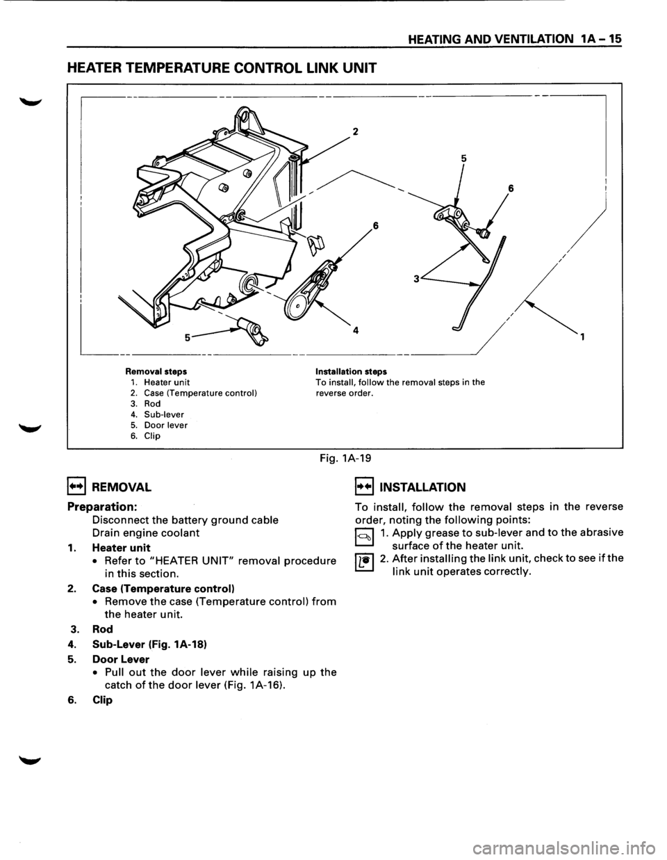
HEATING AND VENTILATION 1A-15
HEATER TEMPERATURE CONTROL LINK UNIT
5
6
/ /
I I
)
1
Removal steps Installation steps 1. Heater unit 2. Case (Temperature control) To install, follow the removal steps in the
reverse order.
3. Rod 4. Sub-lever
5. Door lever 6. Clip
Fig. 1A-19
1••1 REMOVAL
Preparation:
Disconnect the battery ground cable
Drain engine coolant
1. Heater unit
• Refer to "HEATER UNIT" removal procedure
in this section.
2. Case (Temperature control)
• Remove the case (Temperature control) from
the heater unit.
3. Rod
4. Sub-Lever (Fig. 1A-18)
5. Door Lever
• Pull out the door lever while raising up the
catch of the door lever (Fig. 1A-16).
6. Clip
I••! INSTALLATION
To install, follow the removal steps in the reverse
order,
noting the following points:
1~1 1. Apply grease to sub-lever and to the abrasive
surface
of the heater unit.
I L•l 2. After installing the link unit, check to see if the
link unit operates correctly.
Page 46 of 1928
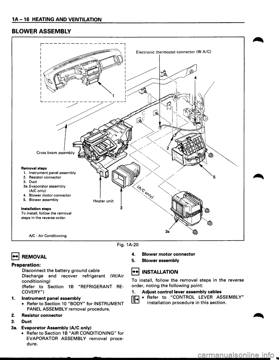
1A-16 HEATING AND VENTILATION
BLOWER ASSEMBLY
Cross beam assembly
Removal steps
1. Instrument panel assembly 2. Resistor connector
3. Duct 3a. Evaporator assembly
lAIC only)
4. Blower motor connector 5. Blower assembly
Installation
steps
To install, follow the removal steps in the reverse order.
A/C -Air Conditioning Heater
unit
Electronic thermostat connector (W A/C)
5
3
3a
Fig.
1A-20
1+•1 REMOVAL
Preparation:
Disconnect the battery ground cable
Discharge and recover refrigerant (W/Air
conditioning)
(Refer to Section 1B "REFRIGERANT RE
COVERY")
1. Instrument panel assembly
• Refer to Section 10 "BODY" for INSTRUMENT
PANEL ASSEMBLY removal
procedure.
2. Resistor connector
3. Duct
3a. Evaporator Assembly (A/C only)
• Refer to Section 1B "AIR CONDITIONING" for
EVAPORATOR ASSEMBLY removal proce
dure.
4. Blower motor connector
5. Blower assembly
I••IINSTALLATION
To install, follow the removal steps in the reverse
order,
noting the following point:
1. Adjust control lever assembly cables
r:C1 • Refer to "CONTROL LEVER ASSEMBLY"
L.:D installation procedure in this section.
Page 47 of 1928
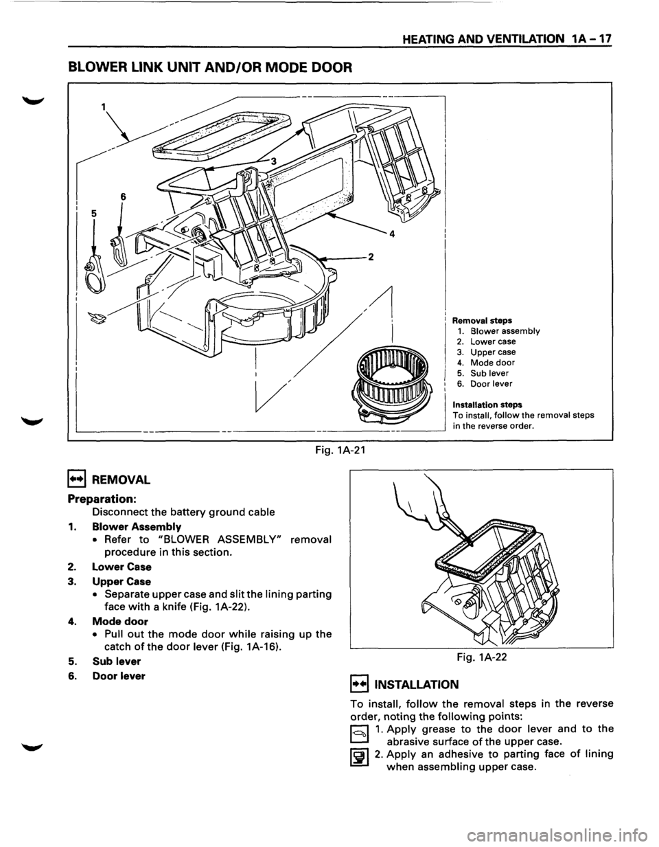
HEATING AND VENTILATION 1A -17
BLOWER LINK UNIT AND/OR MODE DOOR
Removal steps 1. Blower assembly 2. Lower case
3. Upper case 4. Mode door 5. Sub lever 6. Door lever
Installation steps
To install, follow the removal steps
in the reverse order.
Fig. 1A-21
1++1 REMOVAL
Preparation:
Disconnect the battery ground cable
1. Blower Assembly
• Refer to "BLOWER ASSEMBLY" removal
procedure in this section.
2. Lower Case
3. Upper Case
• Separate upper case and slit the lining parting
face with a knife (Fig. 1A-22).
4. Mode door
• Pull out the mode door while raising up the
catch ofthe door lever (Fig. 1A-16).
5. Sub lever
6. Door lever
Fig. 1A-22
I••IINSTALLATION
To install, follow the removal steps in the reverse
order,
noting the following points:
r:::::::l 1. Apply grease to the door lever and to the
D abrasive surface of the upper case.
~~I 2. Apply an adhesive to parting face of lining
when assembling upper case.
Page 48 of 1928
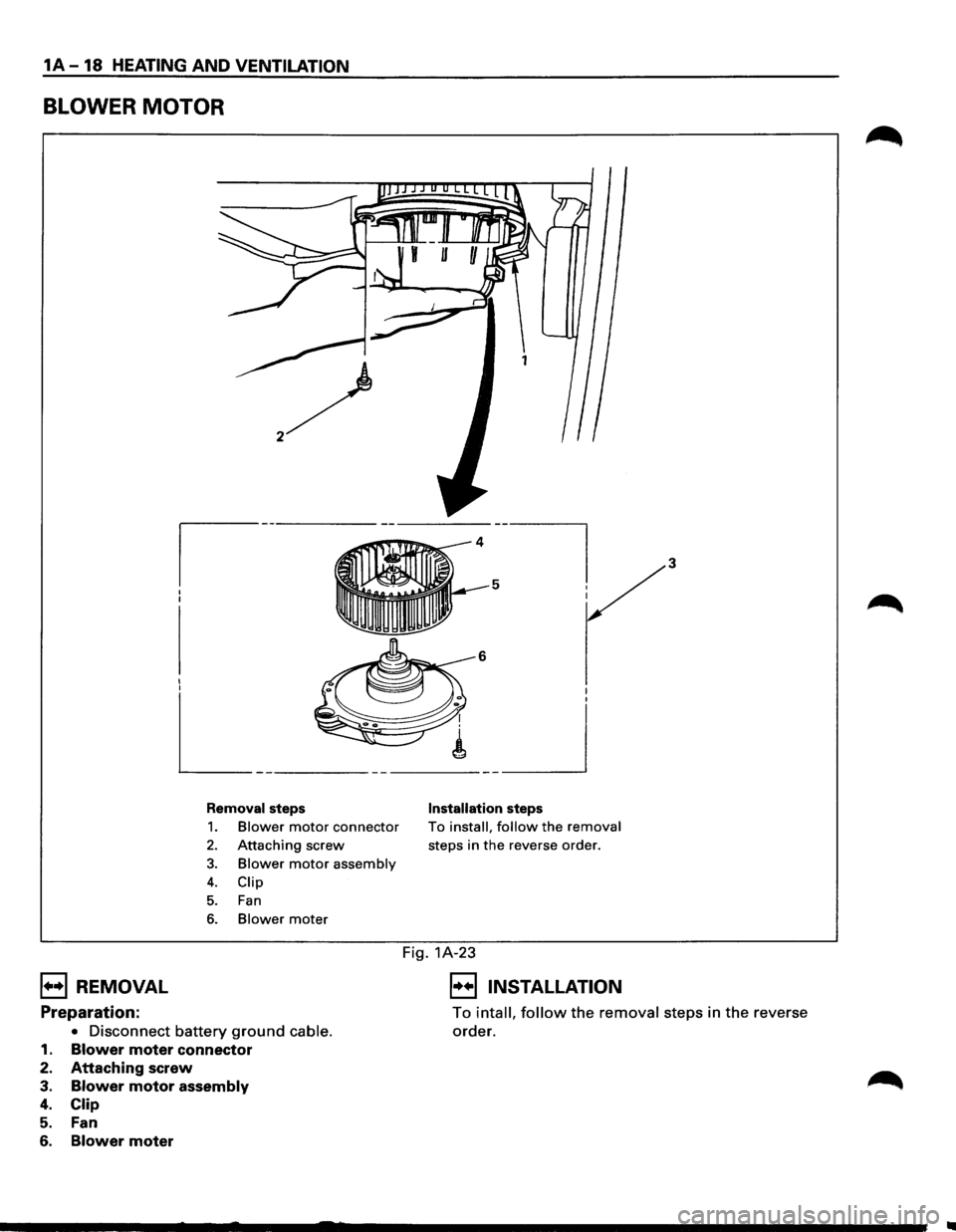
1A-18 HEATING AND VENTILATION
BLOWER MOTOR
I I I I
L_ -----------___ _j
Removal steps
1. Blower motor connector
2. Attaching screw
3. Blower motor assembly
4. Clip
5. Fan
6. Blower mater
Installation steps
To install, follow the removal
steps in the reverse order.
Fig. 1A-23
B REMOVAL 8 INSTALLATION
Preparation:
• Disconnect battery ground cable.
1. Blower moter connector
2. Attaching screw
3. Blower motor assembly
4. Clip
5. Fan
6. Blower moter
To intall, follow the removal steps in the reverse
order.
Page 49 of 1928
HEATING AND VENTILATION 1A-19
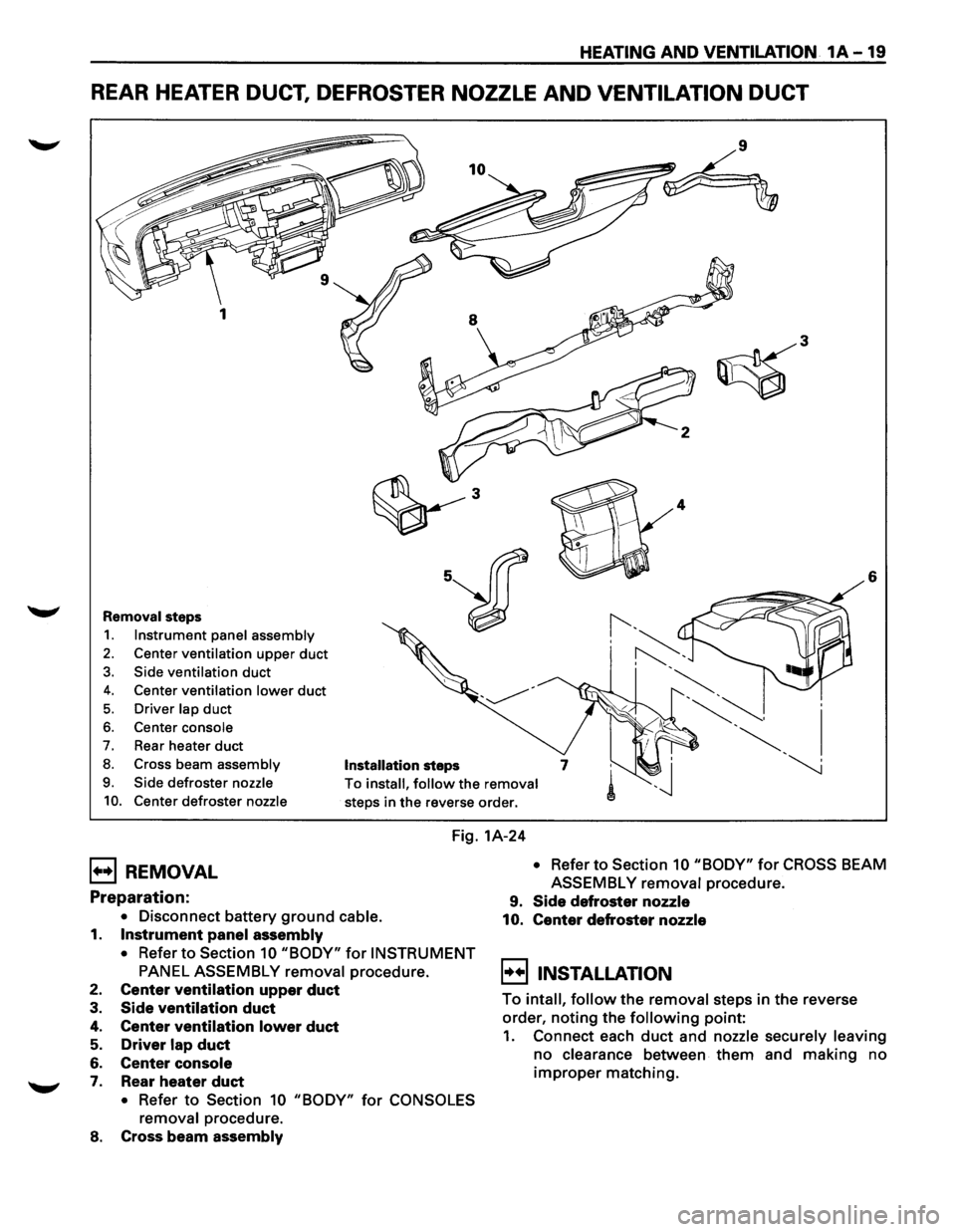
REAR HEATER DUCT, DEFROSTER NOZZLE AND VENTILATION DUCT
6
Removal steps
1. Instrument panel assembly
2. Center ventilation upper duct
3. Side ventilation duct
4. Center ventilation lower duct
5. Driver lap duct
6. Center console
7. Rear heater duct
8. Cross beam assembly Installation steps
9. Side defroster nozzle
10. Center defroster nozzle
To install, follow the removal
steps in the reverse order.
Fig. 1A-24
B REMOVAL
Preparation:
• Disconnect battery ground cable.
1. Instrument panel assembly
• Refer to Section 10 "BODY" for INSTRUMENT
PANEL ASSEMBLY removal procedure.
2. Center ventilation upper duct
3. Side ventilation duct
4. Center ventilation lower duct
5. Driver lap duct
6. Center console
7. Rear heater duct
• Refer to Section 10 "BODY" for CONSOLES
removal
procedure.
8. Cross beam assembly
• Refer to Section 10 "BODY" for CROSS BEAM
ASSEMBLY
removal procedure.
9. Side defroster nozzle
10. Center defroster nozzle
~!!) INSTALLATION
To intall, follow the removal steps in the reverse
order,
noting the following point:
1. Connect each duct and nozzle securely leaving
no clearance between them and making no
improper matching.
Page 50 of 1928
1A-20 HEATING AND VENTILATION
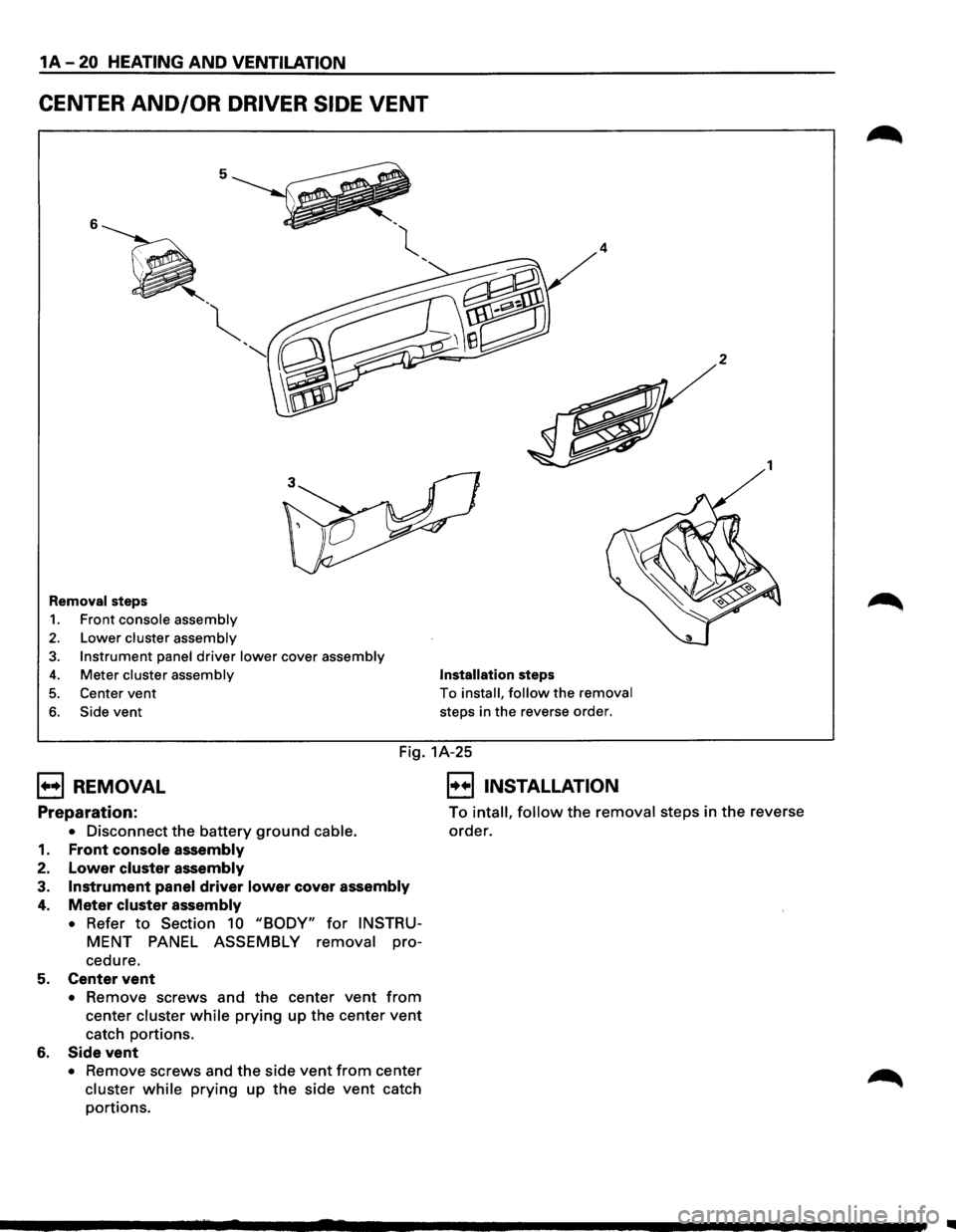
CENTER AND/OR DRIVER SIDE VENT
5
6
' -~
'
"
Removal steps
1. Front console assembly
2. Lower cluster assembly
3. Instrument panel driver lower cover assembly
4. Meter cluster assembly
5. Center vent
6. Side vent
4
Installation steps
To install, follow the removal
steps in the reverse order.
2
1
Fig. 1A-25
B REMOVAL
Preparation:
• Disconnect the battery ground cable.
1. Front console assembly
2. Lower cluster assembly
3. Instrument panel driver lower cover assembly
4. Meter cluster assembly
•
Refer to Section 10 "BODY" for INSTRU
MENT PANEL ASSEMBLY removal pro-
cedure.
5. Center vent
• Remove screws and the center vent from
center cluster while prying up the center vent
catch portions.
6. Side vent
• Remove screws and the side vent from center
cluster while prying up the side vent catch
portions.
E] INSTALLATION
To intall, follow the removal steps in the reverse
order.
..