transmission ISUZU TROOPER 1995 Workshop Manual
[x] Cancel search | Manufacturer: ISUZU, Model Year: 1995, Model line: TROOPER, Model: ISUZU TROOPER 1995Pages: 1928
Page 1218 of 1928
8-28 CHASSIS ELECTRICAL
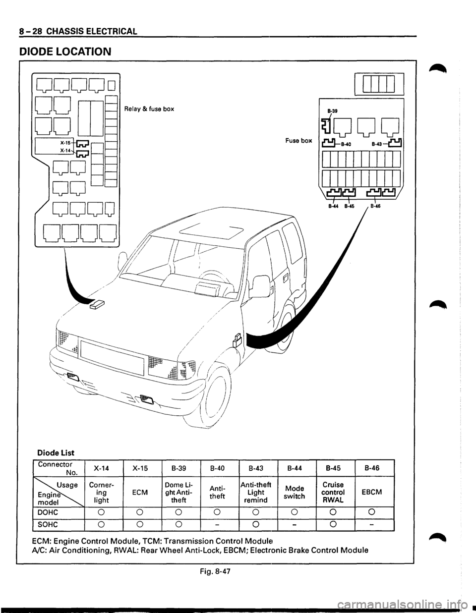
DIODE LOCATION
Relay & fuse box
Fuse box
Diode List
Connector X-14
X-15 B-39 8-40 8-43 8-44
B-45 8-46 No.
~
Corner-Dome Li-Anti-Anti-theft
Mode Cruise ing ECM ghtAnti-
theft Light
switch control EBCM
light
theft remind RWAL
DOHC 0
0 0 0
0 0 0 0
SOHC 0
0 0 -0 -0 -
ECM:
Engine Control Module, TCM: Transmission Control Module1
A/C: Air Conditioning, RWAL: Rear Wheel Anti-Lock, EBCM; Electronic Brake Control Module
Fig. 8-47
•
Page 1219 of 1928
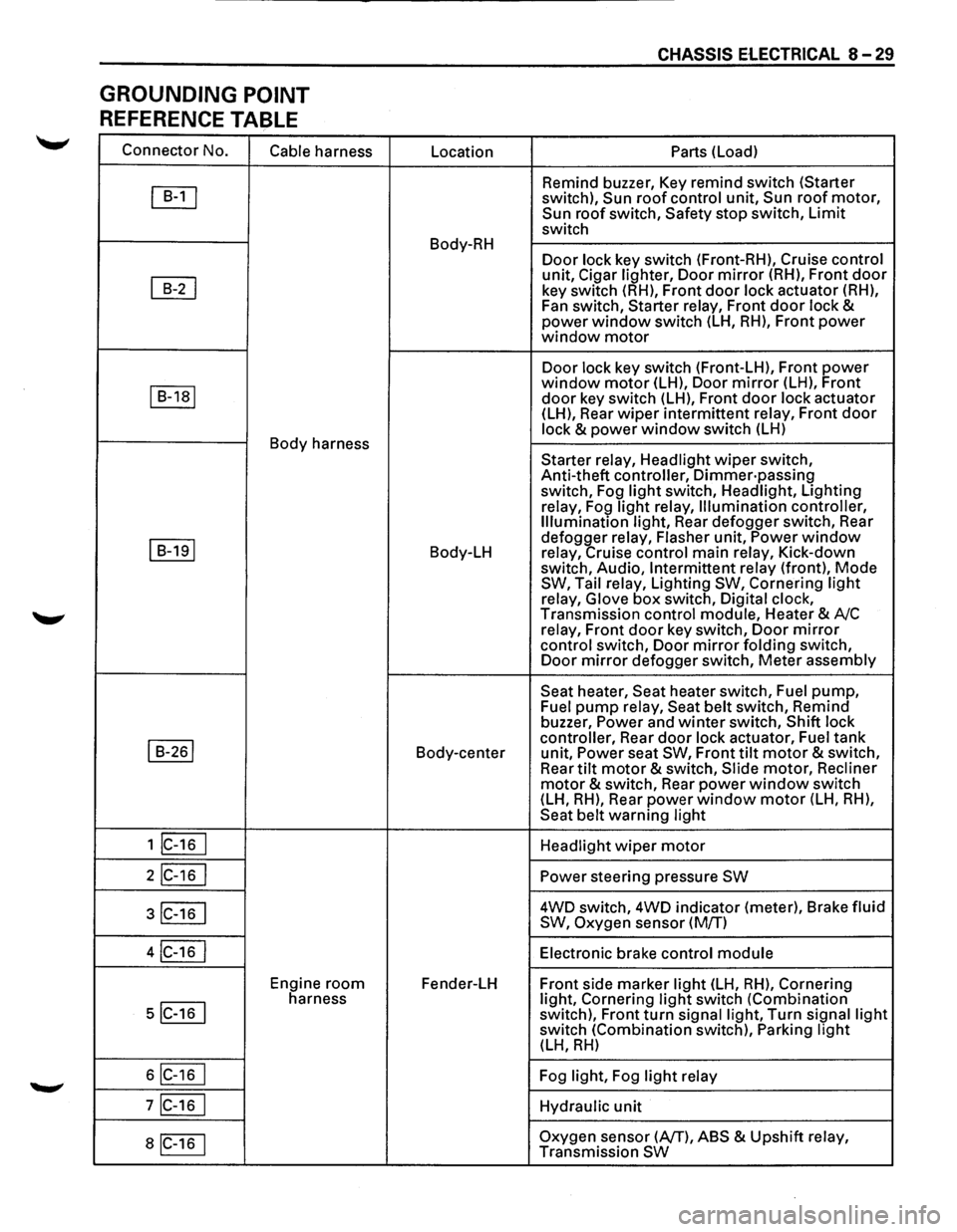
GROUNDING POINT
REFERENCE TABLE
Connector No.
Cable harness
~
~
I B-1a1
Body harness
I B-191
I B-261
1 lc-16 I
2IC-16 I
3IC-16 I
4IC-16 I
Engine room
5IC-16 I
harness
6IC-16 I
7IC-16 I
aiC-16 1
Location
Body-RH
Body-LH
Body-center
Fender-LH
CHASSIS ElECTRICAL 8-29
Parts (Load)
Remind buzzer, Key remind switch (Starter
switch),
Sun roof control unit, Sun roof motor, Sun roof switch, Safety stop switch, Limit
switch
Door lock key switch (Front-RH), Cruise control
unit, Cigar lighter, Door mirror (RH), Front door
key switch (RH), Front door lock actuator (RH),
Fan switch, Starter relay, Front
door lock & power window switch (LH, RH), Front power window motor
Door lock key switch (Front-LH), Front power window motor (LH), Door mirror (LH), Front
door key switch (LH), Front door lock actuator
(LH), Rear wiper intermittent relay, Front door
lock & power window switch (LH)
Starter relay, Headlight
wiper switch,
Anti-theft controller,
Dimmer·passing switch, Fog light switch, Headlight, Lighting
relay, Fog
light relay, Illumination controller,
Illumination light, Rear defogger switch, Rear
defogger relay, Flasher unit,
Power window relay, Cruise control main relay, Kick-down
switch, Audio, Intermittent relay (front), Mode SW, Tail relay, Lighting SW, Cornering light
relay, Glove box switch, Digital clock,
Transmission control module, Heater & A/C
relay, Front
door key switch, Door mirror
control switch, Door mirror folding switch,
Door mirror defogger switch, Meter assembly
Seat heater, Seat heater switch, Fuel pump, Fuel pump relay, Seat belt switch, Remind
buzzer, Power and winter switch, Shift lock
controller, Rear
door lock actuator, Fuel tank
unit, Power seat SW, Front tilt motor & switch,
Rear tilt motor & switch, Slide motor, Recliner
motor & switch, Rear power window switch
(LH, RH), Rear power window motor (LH, RH),
Seat belt warning light
Headlight
wiper motor
Power steering pressure SW
4WD switch, 4WD indicator (meter), Brake fluid
SW, Oxygen sensor (M/T)
Electronic brake control
module
Front side marker light (LH, RH), Cornering
light, Cornering light switch (Combination
switch), Front turn signal light, Turn signal light switch (Combination switch), Parking light (LH, RH)
Fog light, Fog light relay
Hydraulic
unit
Oxygen sensor (AfT), ABS & Upshift relay,
Transmission SW
Page 1220 of 1928
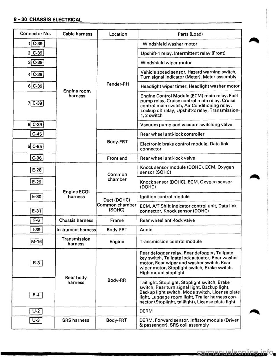
8-30 CHASSIS ELECTRICAL
Connector No.
Cable harness
Location Parts (load)
1jC-39I Windshield washer motor
21 C-391 Upshift-1 relay, Intermittent relay (Front)
31 C-391 Windshield wiper motor
41 C-39j Vehicle speed
sensor, Hazard warning switch,
Turn
signal indicator (Meter), Meter assembly
sl C-391 Fender-RH Headlight wiper timer, Headlight washer motor
Engine room
harness Engine Control Module (ECM)
main relay, Fuel
71 C-391 pump relay, Cruise control main relay, Cruise
control main switch, Air Conditioning relay,
Lockup off relay, Upshift-2 relay, Transmission-
1, 2 switch
al C-391 Vacuum pump and vacuum switching valve
I C-451 Rear wheel anti-lock controller
sl c-asl
Body-FRT Electronic brake control module, Data link
connector
I C-961 Front end Rear wheel
anti-lock valve
I E-281 Knock sEmsor module (DOHC), ECM, Oxygen
Common sensor (SOHC)
I E-291 chamber Knock sensor (DOHC), ECM, Oxygen sensor
(DOHC)
Engine
ECGI
I E-30 I harness Duct (DOHC) Ignition control
module
Common chamber
ECM, AfT Shift indicator control unit, Data link
I
E-311 (SOHC) connector, Knock sensor (DOHC)
~ Chassis harness Frame
Rear wheel anti-lock valve
11-391 Instrument
harness
Body-FRT Audio
IM-161 Transmission
Engine Transmission control module harness
Rear defogger
relay, Rear defogger, Tailgate
~
key switch, Tailgate lock actuator, Rear washer
motor, A:ear wiper and washer switch, Rear
wiper motor, Stoplight switch, Brake switch,
High
mount stoplight
Rear body Body-RR
harness Taillight, Stoplight, Stoplight switch, Brake
switch,
near turn signal light, Backup light,
~
Backup light switch, Mode switch, License plate
light, Lu!;)gage room light, Trailer harness con-
nector
(Stoplight, taillight), License plate light
~ DERM
00 SRS harness Body-FRT
DERM, Forward sensor, Inflator module (Driver
& passenger),
SRS coil assembly
•
Page 1224 of 1928
![ISUZU TROOPER 1995 Workshop Manual :n <0 00 I (11 ...
)
RR
DOOR HARNESS
(RH)
DOME LIGHT HARNESS
[INSTRUMENT
HARNESS
I
[BODY
HARNESS
l.,
\\V~;'ff
FRT
DOOR HARNESS
(RHl
~
RELAY
& FUSE BOX
~.
(FL-1, FL-2, FL](/img/61/57183/w960_57183-1223.png "ISUZU TROOPER 1995 Workshop Manual :n <0 00 I (11 ...
)
RR
DOOR HARNESS
(RH)
DOME LIGHT HARNESS
[INSTRUMENT
HARNESS
I
[BODY
HARNESS
l.,
\\V~;'ff
FRT
DOOR HARNESS
(RHl
~
RELAY
& FUSE BOX
~.
(FL-1, FL-2, FL")
:n <0 00 I (11 ...
)
RR
DOOR HARNESS
(RH)
DOME LIGHT HARNESS
[INSTRUMENT
HARNESS
I
[BODY
HARNESS
l.,
\\V~;'ff
FRT
DOOR HARNESS
(RHl
~
RELAY
& FUSE BOX
~.
(FL-1, FL-2, FL-3, FL-6,
F-1
-F-12)
P-5.
BATIERY---
""· "·
P-1
H-1--f~
BATIERY~)CABLE'~
C-39
)
'\\. RR
DOOR
HARNESS
(LHl
BODY HARNESS
FRT
DOOR HARNESS
(LH)
FUSE BOX
(C-1
-C-24)
TRANSMISSION HARNESS
: .. · .. ; ')
0
co
):>
I
IXJ
w
r-
~
m
(")
:I:
::I:
):>
)>
::0
en
2
en
m
Cii
(/)
m
(/)
r-
::0
m (")
0
-4
c
:a
-1
0
2
)>
C)
r-
Page 1234 of 1928
8-44 CHASSIS ELECTRICAL
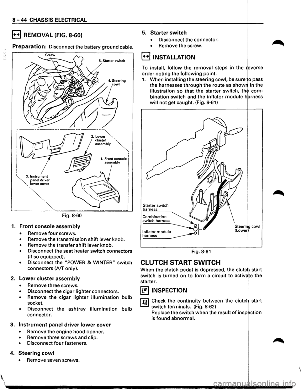
B REMOVAL (FIG. 8-60)
Preparation: Disconnect the battery ground cable.
5. Starter switch
Fig. 8-60
1. Front console assembly
• Remove four screws.
• Remove the transmission shift lever knob.
• Remove the transfer shift lever knob.
• Disconnect the seat heater switch connectors
(If so equipped).
• Disconnect the "POWER & WINTER" switch
connectors
(A/T only).
2. Lower cluster assembly
• Remove three screws.
• Disconnect the cigar lighter connectors.
• Remove the cigar lighter illumination bulb
socket.
• Disconnect the ashtray illumination bulb
connector.
3. Instrument panel driver lower cover
• Remove the engine hood opener.
• Remove three screws and clip.
• Disconnect four fasteners.
4. Steering cowl
• Remove seven screws .
5. Starter switch
• Disconnect the connector.
• Remove the screw.
B INSTALLATION
To install, follow the removal steps in the everse
order noting the
following point.
1. When installing the steering cowl, be sure o pass
the harnesses through the route as
show in the
illustration so that the starter switch, th com
bination switch and the inflator
module
will not get caught. (Fig. 8-61)
Starter switch
harness
Fig. 8-61
CLUTCH START SWITCH
cowl
When the clutch pedal is depressed, the clute start
switch is turned on
to form a circuit to activ e the
starter.
~ INSPECTION
1 til!. I Check the continuity between the clute start
switch terminals. (Fig. 8-62)
Replace the switch when the result
of insp ction
is found abnormal.
'
Page 1241 of 1928
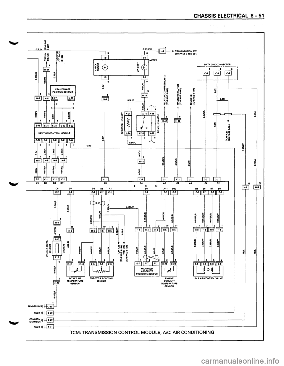
w " ~~ O.SLJY ~ ..
2"' a~ u$ ~f~ ~~ ~g~
FENDER-RH II
DUCT II
~~~~~II
DUCT II
INTAKE AIR TEMPERATURE SENSOR
~~ 0~
a; d
0.89
C-1 A&
THROTTLE POSITION
SENSOR
... 5! ., .. ::> 0: ~
m
0.85LIO
~ a d d
li~Ui"o:i UOlUCJI> i;i;i:b ~wuw "'"" ~ ~ g g
"' il " Ill
13
§
; w 0 0: .. 5N ~;:; 8<:1 d~ u"' ~~ ~~ ~~ z< ., .. ~g ~g
~ § :;1 ~ d
0: " Ill d
ENGINE COOLANT
TEMPERATURE
SENSOR
CHASSIS ELECTRICAL 8-51
~ ~ ~w _.,
i£ ~g
~ i ;zf d
d
IIi ~ d .. :b
~~ ~g
~
"' ~ 5I d "'
13 12 H-6 H-6
.. ~ "' ~ il il
!
! ! ~
~ ~ I ~ CD ! ! ~
i
i
TCM: TRANSMISSION CONTROL MODULE, A/C: AIR CONDITIONING
Page 1243 of 1928
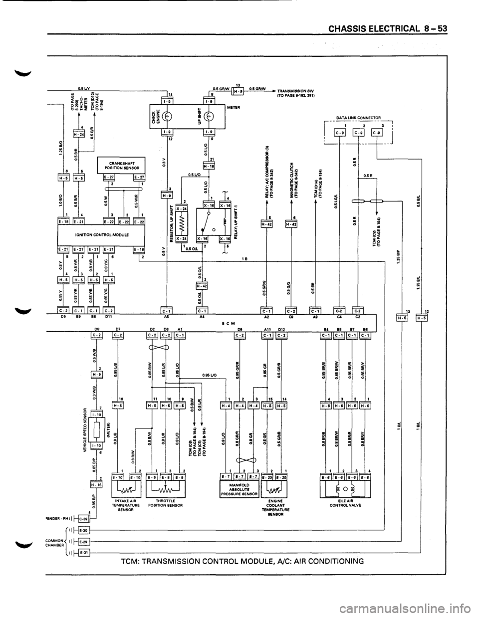
0.5 LJV
E C M
.. ~ ~ g ~ ::r <3 ::! ~ ~ IB Ill d 0 d 0.85 LJO d
16 10 ~ ~ H-6 ~ ~
: : 3 ~ ~ ;;; ;;; .. 3~ ~~ ~ " 0 ~ I -f -:
~I
~g~g
INTAKE AIR THROTTLE TEMPERATURE POSITION SENSOR
SENSOR
'ENDER-RH II
f-'0""·5,;G,RIN!!!!.__,~ TRANSMISSION SW (TO PAGE 8-182. 281)
a
~ .. % IE u 21<1 3~ i 8<=~
~= u .. ;;;
~~ '"'" ~~
_.., j§L e.~ 2o ll!g ig l:!t::
a: ~ i <3 <3 IB .. IB d
d
d
a: a: ~ ~ <3 " .. .. .. d d ~ ~
CHASSIS ELECTRICAL 8 ... 53
~ ... .. d
~ ..
~
~ .. ~
i IB d
~ .. ~
a: .. d
13 1Z H-5 H-5
i IB d
iil iil
~ .. .. 0
COMMON{::~------------------------------------------------------------------------------------------~ CHAMBER r·-l::.:!!J
II E-311-'----------------------------------------------------------------------------------------------~
TCM: TRANSMISSION CONTROL MODULE, A/C: AIR CONDITIONING
Page 1264 of 1928
8-74 CHASSIS ELECTRICAL
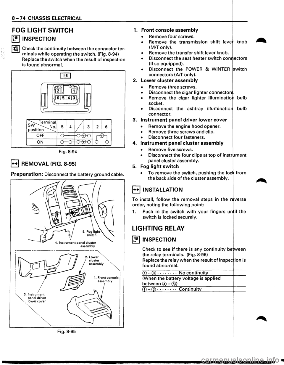
FOG LIGHT SWITCH
~ INSPECTION
I tgj Check the continuity between the connector ter
minals
while operating the switch. (Fig. 8-94)
Replace the switch when the result of inspection
is found abnormal.
ru~
IT
2 [II
161514131
c-
Fig. 8-94
B REMOVAL (FIG. 8-95)
TI ';
Preparation: Disconnect the battery ground cable.
Fig.
8-95
I I 1. Front console I assembly
1. Front console assembly
• Remove four screws.
• Remove the transmission shift leve knob
(M!r only).
• Remove the transfer shift lever knob.
• Disconnect the seat heater switch con ectors
(If so equipped).
• Disconnect the POWER & WINTER switch
connectors
(A/T only).
2.
Lower cluster assembly
• Remove three screws.
• Disconnect the cigar lighter connector .
• Remove the cigar lighter illuminatio bulb
socket.
• Disconnect the ashtray illuminatio bulb
connector.
3.
Instrument panel driver lower cover
• Remove the engine hood opener.
• Remove three screws and clip.
• Disconnect four fasteners.
4.
Instrument panel cluster assembly
• Remove five screws.
• Disconnect the four clips at top of instr ment
panel cluster assembly.
5. Fog
light switch
• To remove the switch, pushing the loc from
the back side of the cluster assembly.
B INSTALLATION
To install, follow the removal steps in the r verse
order, noting the
following point:
1. Push in the switch with your fingers un il the
switch is locked securely.
LIGHTING RELAY
~ INSPECTION
Check to see if there is any continuity be ween
the relay terminals. (Fig.
8-96)
Replace the relay when the result of in spec ion is
found abnormal.
CD-3 · · · · • · · · No continuit
(When the battery voltage is applied
between
4 -s)
•
Page 1306 of 1928
-
8-116 CHASSIS ELECTRICAL
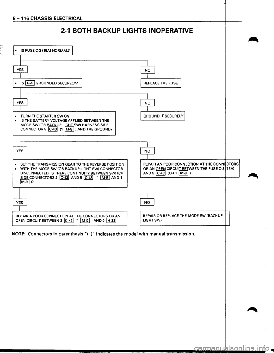
2-1 BOTH BACKUP LIGHTS INOPERATIVE
• IS FUSE C-3 (15A) NORMAL? I
I
I
YES I
I
• IS ~GROUNDED SECURELY? I
I
I
YES I
I
• TURN THE STARTER SW ON
• IS THE BATIERY VOLTAGE APPLIED BETWEEN THE
MODE
SW lOR BACKUP LIGHT SW) HARNESS SIDE coNNECTOR 5 I C-431 11 I M-al >AND THE GROUND?
I
I
YES .J
I
• SET THE TRANSMISSION GEAR TO THE REVERSE POSITION
• WITH
THE MODE SW !OR BACKUP LIGHT SW) CONNECTOR
DISCONNECTED, IS THERE CONTINUITY BETWEEN SWITCH
SIDE
coNNECTORS 2 lc-431 AND 5 I C-431 11 I M-al AND 1 IM-91 )?
I
J
YES I
I
REPAIR A POOR CONNECTION AT THE CONNECTORS OR AN
OPEN CIRCUIT BETWEEN 2 I C-431 ( 1 I M-91 ) AND 9 I H-321
I
NO j
I
REPLACE THE FUSE j
I
NO I
I
GROUND IT SECURELY I
I
NO I
I
REPAIR AN POOR CONNECTION AT THE CONNECTORS
OR AN OPEN CIRCUIT BETWEEN THE FUSE C-3 15A)
AND 5 lc-431 !OR 1 I M-al 1
I
NO I
I
REPAIR OR REPLACE THE MODE SW (BACKUP LIGHTSW)
NOTE: Connectors in parenthesis "( )" indicates the model with manual transmission.
..
Page 1313 of 1928
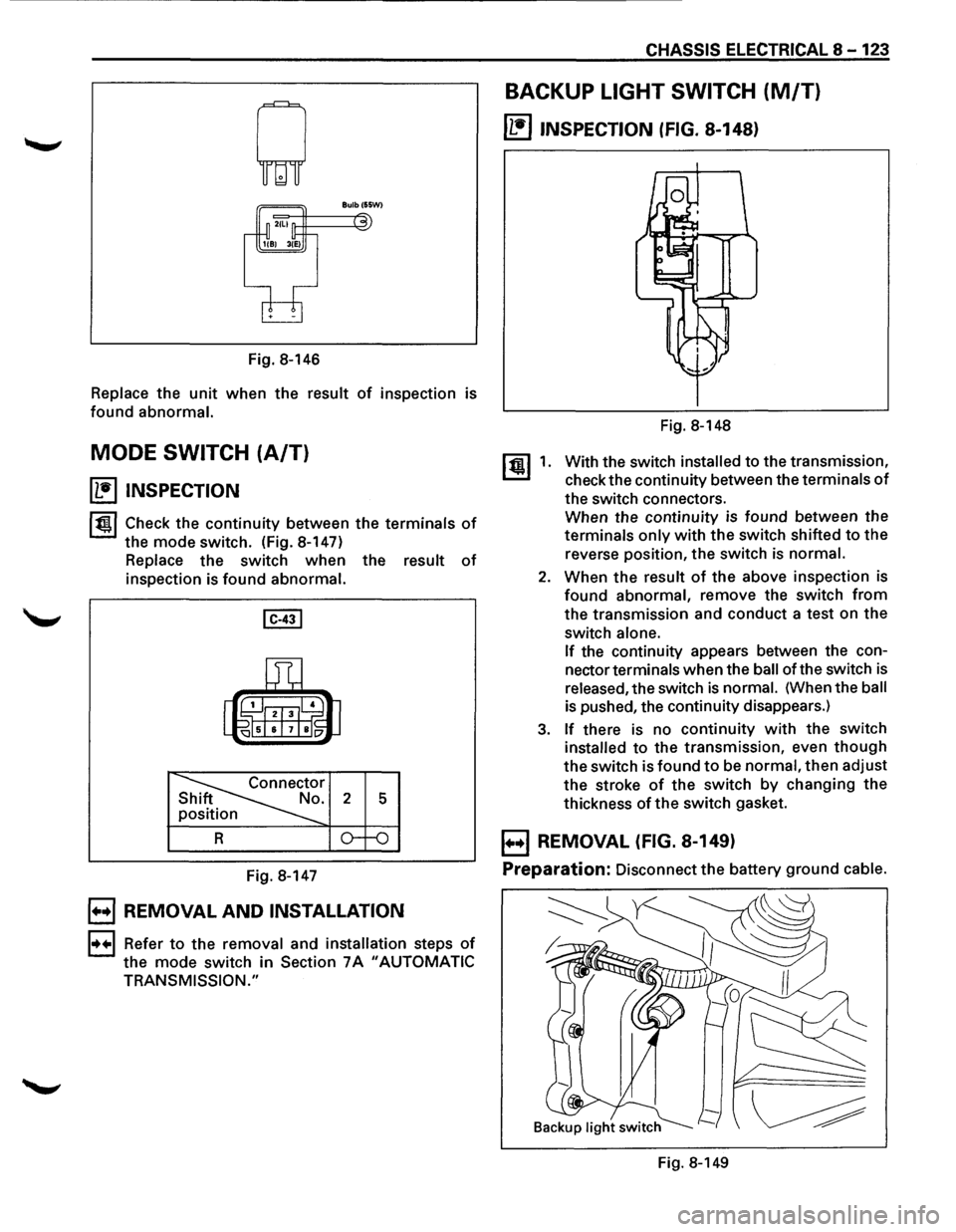
Fig. 8-146
Replace the unit when the result of inspection is
found abnormal.
MODE SWITCH (A/T)
~ INSPECTION
1~1 Check the continuity between the terminals of
the mode switch. (Fig. 8-147)
Replace the switch when the result of
inspection is found abnormal.
Fig. 8-147
B REMOVAL AND INSTALLATION
1••1 Refer to the removal and installation steps of
the mode switch in Section 7A "AUTOMATIC
TRANSMISSION."
CHASSIS ELECTRICAL 8-123
BACKUP LIGHT SWITCH (M/T)
~ INSPECTION (FIG. 8-148}
[!) 1.
Fig. 8-148
With the switch
installed to the transmission,
check the continuity between the
terminals of
the switch connectors.
When the continuity is found between the
terminals only with the switch shifted to the
reverse position, the switch
is normal.
2. When the result of the above inspection is
found abnormal, remove the switch from
the transmission and conduct a test on the
switch
alone.
If
the continuity appears between the con
nector
terminals when the ball of the switch is
released, the switch is normal. (When the ball
is pushed, the continuity disappears.)
3. If there is no continuity with the switch
installed to the transmission, even though
the switch is found to be normal, then adjust
the stroke
of the switch by changing the
thickness
of the switch gasket.
B REMOVAL (FIG. 8-149}
Preparation:
Disconnect the battery ground cable.
Fig. 8-149