brake sensor ISUZU TROOPER 1995 Owner's Guide
[x] Cancel search | Manufacturer: ISUZU, Model Year: 1995, Model line: TROOPER, Model: ISUZU TROOPER 1995Pages: 1928
Page 402 of 1928
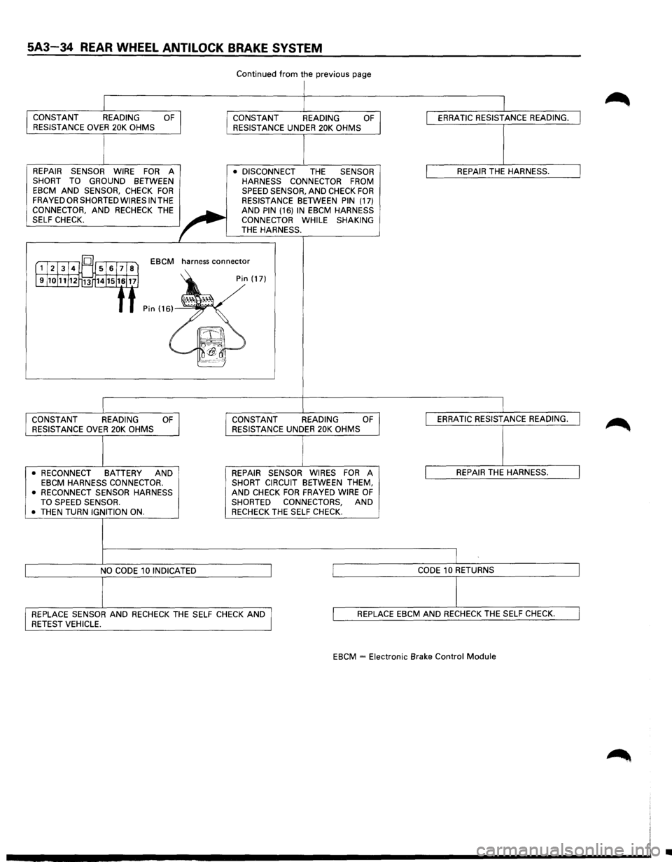
5A3-34 REAR WHEEL ANTILOCK BRAKE SYSTEM
CONSTANT READING OF RESISTANCE OVER 20K OHMS
REPAIR SENSOR WIRE
FOR A SHORT TO GROUND BETWEEN EBCM AND SENSOR, CHECK FOR FRAYED OR SHORTED WIRES IN THE CONNECTOR, AND RECHECK THE SELF CHECK.
Continued from the previous page
I
CONSTANT READING OF RESISTANCE UNDER 20K OHMS
• DISCONNECT
THE SENSOR
HARNESS CONNECTOR FROM
SPEED SENSOR, AND CHECK FOR RESISTANCE BETWEEN PIN (17)
AND PIN (16) IN EBCM HARNESS
CONNECTOR WHILE SHAKING
THE HARNESS.
= [',...,J-2.,..1-3..--14....,l~'l's...,, 1-6-.-17, la"'l EBCM
harness connector
l9l10111112t~ 14Jl5116117) :) Pin (17)
f f Pin (166~,~~.
!.TJ -I
~~···~
CONSTANT READING OF RESISTANCE OVER 20K OHMS
• RECONNECT
BATTERY AND EBCM HARNESS CONNECTOR.
• RECONNECT SENSOR HARNESS
TO SPEED SENSOR.
•
THEN TURN IGNITION ON.
NO
CODE 10 INDICATED CONSTANT
READING
OF I RESISTANCE UNDER 20K OHMS
REPAIR SENSOR WIRES
FOR A SHORT CIRCUIT BETWEEN THEM,
AND CHECK FOR FRAYED WIRE OF SHORTED CONNECTORS, AND RECHECK THE SELF CHECK.
I l
I ERRATIC RESISTANCE READING. I
l REPAIR THE HARNESS. I
I
ERRATIC RESISTANCE READING. I
I REPAIR THE HARNESS. I
I CODE 10 RETURNS I
I REPLACE SENSOR AND RECHECK THE SELF CHECK AND I RETEST VEHICLE. l REPLACE EBCM AND RECHECK THE SELF CHECK. I
EBCM -Electronic Brake Control Module
•
Page 408 of 1928
5A3-40 REAR WHEEL ANTILOCK BRAKE SYSTEM
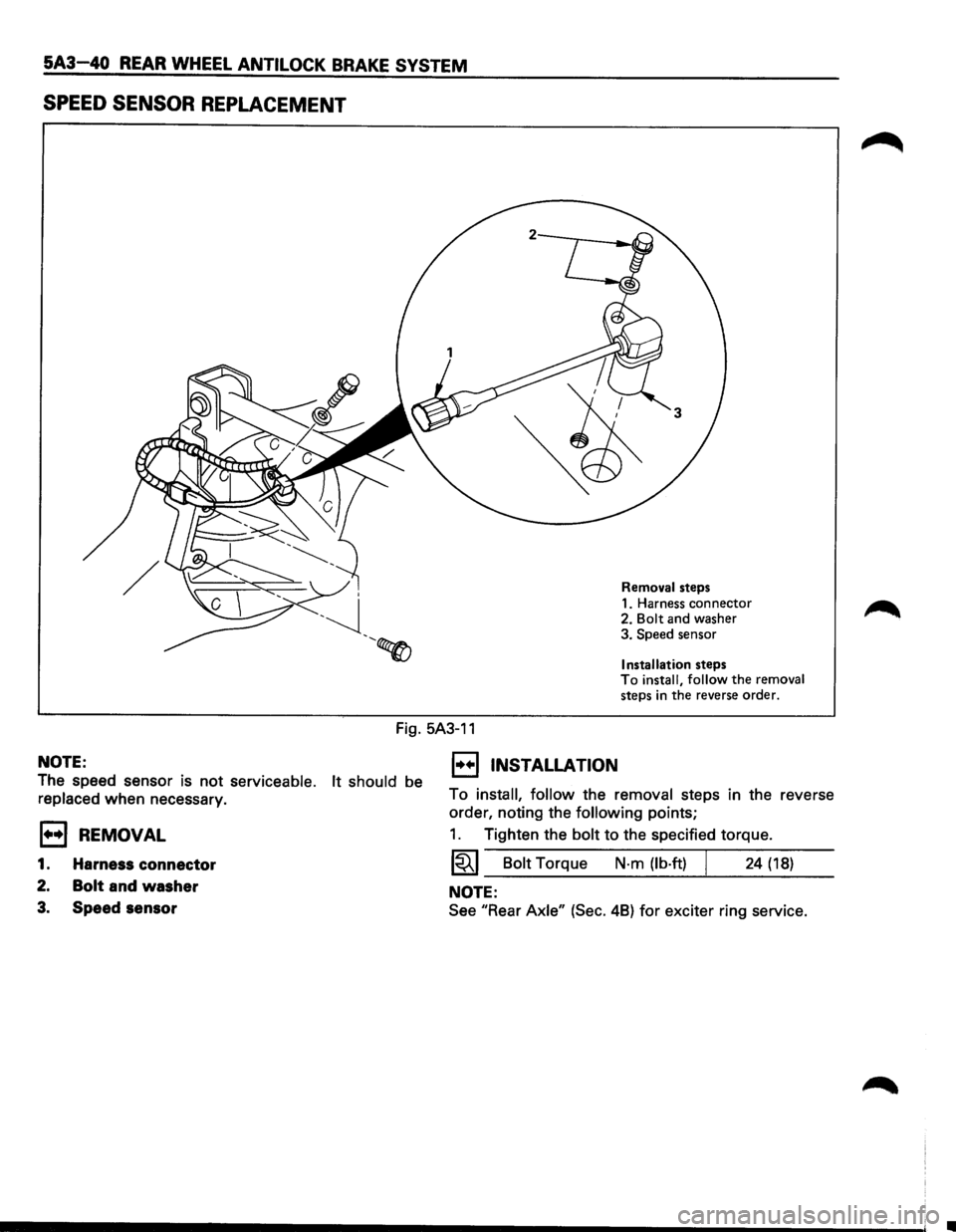
SPEED SENSOR REPLACEMENT
Removal steps
1. Harness connector
2.
Bolt and washer
3. Speed sensor
Installation steps To install, follow the removal
steps in the reverse order.
Fig. 5A3-11
NOTE:
The speed sensor is not serviceable. It should be
replaced when necessary.
E3 REMOVAL
1. Harness connector
2. Bolt and washer
3. Speed sensor
1••1 INSTALLATION
To install, follow the removal steps in the reverse
order, noting the
following points;
1. Tighten the bolt to the specified torque.
1~1 Bolt Torque N-m {lb·ft) I 24 {18)
NOTE:
See "Rear Axle" {Sec. 48) for exciter ring service.
Page 411 of 1928
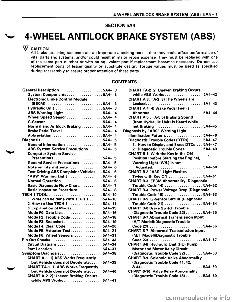
4-WHEEL ANTILOCK BRAKE SYSTEM (ABS) 5A4-1
SECTION 5A4
'--' 4-WHEEL ANTILOCK BRAKE SYSTEM (ABS)
CAUTION
All
brake attaching fasteners are an important attaching part in that they could affect performance of
vital parts and systems, and/or could result in major repair expense. They must be replaced with one
of the same part number or with an equivalent part if replacement becomes necessary. Do not use
replacement parts
of lesser quality or substitute design. Torque values must be used as specified
during reassembly to assure proper retention of these parts.
CONTENTS
General Description .................... 5A4-3
System Components ................. 5A4-3
Electronic Brake
Control Module ·
(EBCM) .......................... 5A4-3
Hydraulic Unit ...................... 5A4-3
ABS Warning Light .................. 5A4-4
Wheel
Speed Sensor ................. 5A4-4
G-Sensor
........................... 5A4-4
Normal and Antilock Braking .......... 5A4-4
Brake Pedal Travel
................... 5A4-4
Abbreviation ........................ 5A4-4
Diagnosis
............................. 5A4-5
General
Information ................. 5A4-5
ABS
System Service Precautions ....... 5A4-5
Computer System Service
Precautions
....................... 5A4-5
General Service Precautions
........... 5A4-5
Note on lntermittents ................ 5A4-6
Test Driving ABS Complaint Vehicles ... 5A4-6
II ABS11 Warning Light ................ 5A4-6
Normal Operation ................... 5A4-6
Basic
Diagnostic Flow Chart ........... 5A4-7
Basic
Inspection Procedure ............ 5A4-8
TECH 1
TOOL. ......................... 5A4-10
1. What can be done with TECH 1 ...... 5A4-10
2. How to Use TECH 1 ................ 5A4-11
3. Explanation of Modes .............. 5A4-15
Mode FO: Data List ................... 5A4-16
Mode F2: Trouble Code ............... 5A4-18
Mode F3: Snapshot .................. 5A4-19
Mode F4: Clear Code ................. 5A4-20
Mode F5: Actuator Test ............... 5A4-21
Mode F6: Wheel Sensors ............. 5A4-31
Pin-Out Checks ........................ 5A4-33
Circuit Diagram ..................... 5A4-34
Part Location ....................... 5A4-37
Symptom Diagnosis .................... 5A4-38
CHART A-1 1) ABS Works Frequently
but Vehicle does not Decelerate ...... 5A4-39
CHART TA-1 1) ABS Works Frequently
but Vehicle does not Decelerate ...... 5A4-40
CHART A-2 2) Uneven Braking Occurs
while ABS Works .................. 5A4-41
CHART TA-2 2) Uneven Braking Occurs
while ABS Works .................. 5A4-42
CHART A-3, T A-3 3) The Wheels are
Locked
........................... 5A4-43
CHART A-4 4) Brake Pedal Feel is
Abnormal ........................ 5A4-44
CHART A-5 , T A-5 5) Braking Sound
(from Hydraulic Unit) is Heard while
not Braking ....................... 5A4-45
Diagnosis by 11 ABS11 Warning Light
Illumination Pattern .................. 5A4-46
Diagnostic Trouble Codes (DTCs) ....... 5A4-47
1. How to Display and Erase DTCs ... 5A4-47
2. Diagnostic Trouble Codes ........ 5A4-49
CHART B-1 With the Key in the ON
Position (before Starting the Engine),
Warning Light (W /L) is not
•
Actuated ........................ 5A4-50
CHART B-2 II ABSII Light Flashes
Twice with Key ON ................ 5A4-51
CHART B-3 EBCM Abnormality (Diagnostic
Trouble Code 14) .................. 5A4-52
CHART B-4 Power Voltage Drop (Diagnostic
Trouble Code 15) .................. 5A4-53
CHART B-5 G-Sensor Circuit (Diagnostic
Trouble Code 21) .................. 5A4-54
CHART B-6 Brake Switch Trouble
(Diagnostic Trouble Code 22) ........ 5A4-55
CHART B-7 Abnormal Transmission Input
(A/T Modei)(Diagnostic Trouble
Code 23) ......................... 5A4-56
CHART B-7 Abnormal Transmission Input
(M/T Modei)(Diagnostic Trouble
Code 23) ......................... 5A4-57
CHART B-8 Hydraulic Unit (HU) Pump
Motor and Motor Relay Circuit
(Diagnostic Trouble Code 32) ........ 5A4-58
CHART B-9 Solenoid Valve Abnormality
(Diagnostic Trouble Code 41, 42,
& 44) ............................ 5A4-59
CHART B-10 Valve Relay Abnormality
(Diagnostic Trouble Code 45) ........ 5A4-60
Page 412 of 1928
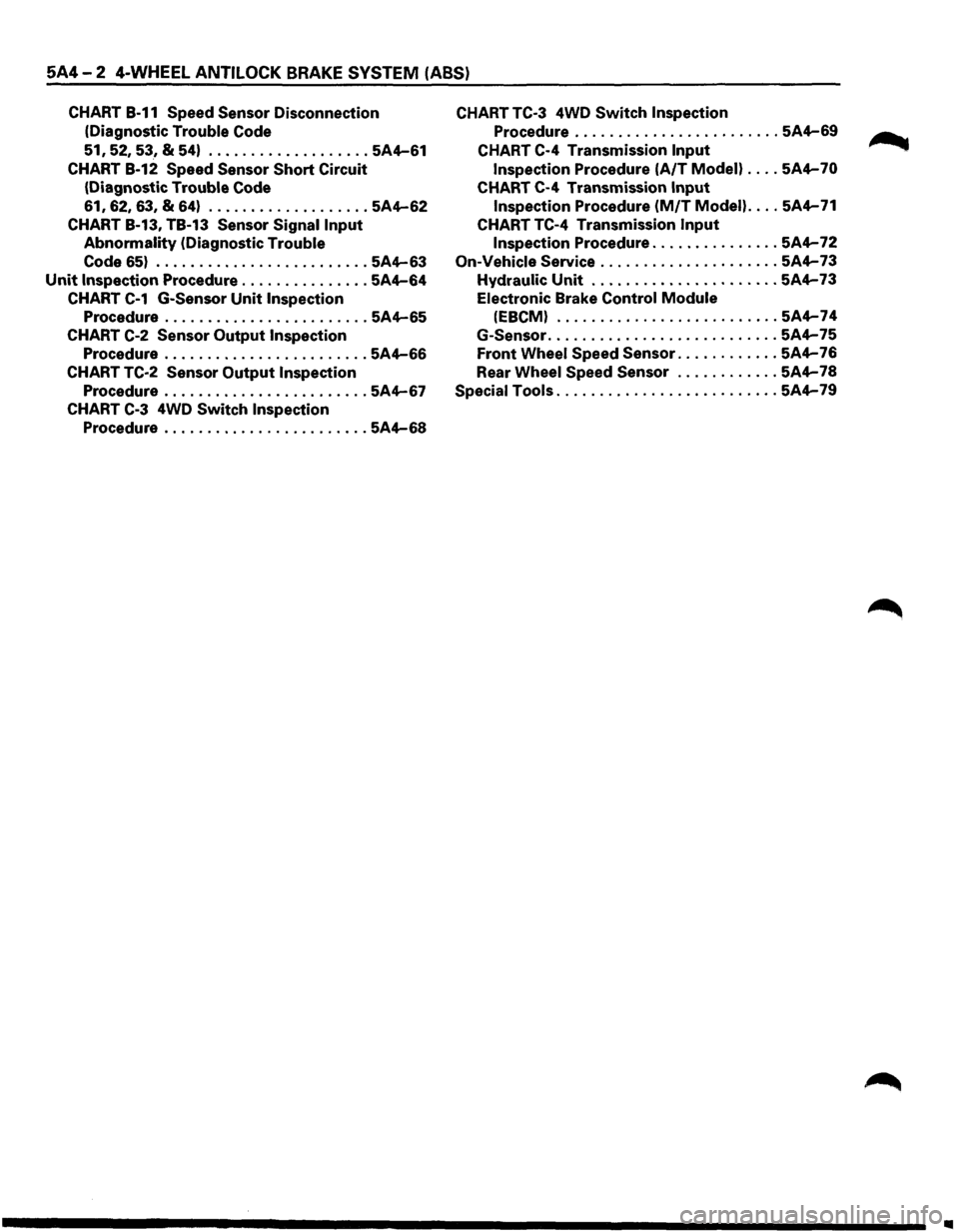
5A4-2 4-WHEEL ANTILOCK BRAKE SYSTEM (ABS)
CHART B-11 Speed Sensor Disconnection
(Diagnostic
Trouble Code
51, 52, 53, & 54) ................... 5A4-61
CHART B-12 Speed Sensor Short Circuit
(Diagnostic Trouble Code
61, 62,
63,
& 64) ................... 5A4-62
CHART B-13, TB-13 Sensor Signal Input
Abnormality (Diagnostic Trouble
Code
65) ......................... 5A4-63
Unit Inspection Procedure ............... 5A4-64
CHART C-1 G-Sensor Unit Inspection
Procedure ........................ 5A4-65
CHART C-2 Sensor Output Inspection
Procedure ........................ 5A4-66
CHART TC-2 Sensor Output Inspection
Procedure ........................ 5A4-67
CHART C-3 4WD Switch Inspection
Procedure ........................ 5A4-68
CHART TC-3 4WD Switch Inspection
Procedure ........................ 5A4-69
CHART C-4 Transmission Input
Inspection Procedure (A/T Modell .... 5A4-70
CHART C-4 Transmission Input
Inspection Procedure (M/T Model) .... 5A4-71
CHART TC-4 Transmission Input
Inspection Procedure ............... 5A4-72
On-Vehicle Service ..................... 5A4-73
Hydraulic Unit ...................... 5A4-73
Electronic Brake Control Module
(EBCMI .......................... 5A4-74
G-Sensor ........................... 5A4-75
Front Wheel Speed Sensor ............ 5A4-76
Rear
Wheel Speed Sensor ............ 5A4-78
Special Tools .......................... 5A4-79
..
Page 413 of 1928
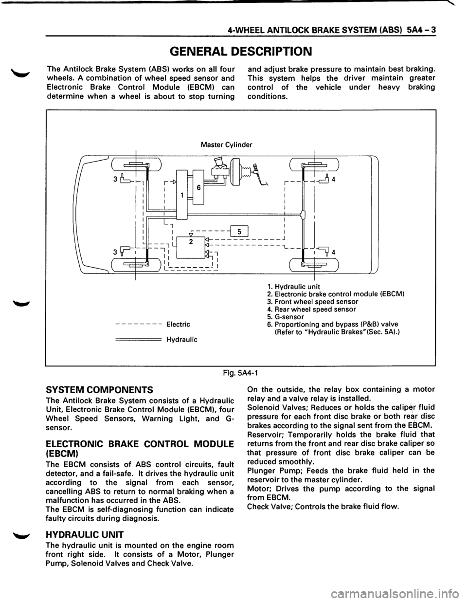
4-WHEEL ANTILOCK BRAKE SYSTEM (ABS) 5A4-3
GENERAL DESCRIPTION
The Antilock Brake System (ASS) works on all four
wheels. A combination of wheel speed sensor and
Electronic Brake Control Module (EBCM) can
determine
when a wheel is about to stop turning
and adjust brake pressure to maintain best braking.
This system
helps the driver maintain greater
control of the vehicle under heavy braking
conditions.
Master Cylinder
I I I I
--------Electric
===== Hydraulic
,--1 I
I
I
-ld4
1. Hydraulic unit 2. Electronic brake control module (EBCM)
3. Front wheel speed sensor 4. Rear wheel speed sensor
5. G-sensor 6. Proportioning and bypass (P&Bl valve
(Refer to "Hydraulic Brakes"(Sec. 5A).)
Fig. 5A4-1
SYSTEM COMPONENTS
The Antilock Brake System consists of a Hydraulic
Unit, Electronic Brake Control Module (EBCM), four
Wheel Speed Sensors, Warning Light, and G
sensor.
ELECTRONIC BRAKE CONTROL MODULE
(EBCM)
The EBCM consists of ABS control circuits, fault
detector, and a fail-safe. It drives the hydraulic unit
according to the signal from each sensor,
cancelling ABS to return to normal braking when a
malfunction has occurred in the ABS.
The EBCM is self-diagnosing function can indicate
faulty circuits during diagnosis.
'--" HYDRAULIC UNIT
The hydraulic unit is mounted on the engine room
front right side. It consists of a Motor, Plunger
Pump, Solenoid Valves and Check Valve. On
the
outside, the relay box containing a motor
relay and a valve relay is installed.
Solenoid Valves;
Reduces or holds the calip~r fluid
pressure for each front disc brake or both rear disc
brakes according
to the signal sent from the EBCM.
Reservoir;
Temporarily holds the brake fluid that
returns from the front and rear disc brake caliper so
that pressure of front disc brake caliper can be
reduced
smoothly.
Plunger
Pump; Feeds the brake fluid held in the
reservoir
to the master cylinder.
Motor; Drives the pump according to the signal
from EBCM.
Check
Valve; Controls the brake fluid flow.
Page 414 of 1928
5A4-4 4-WHEEL ANTILOCK BRAKE SYSTEM (ABS)
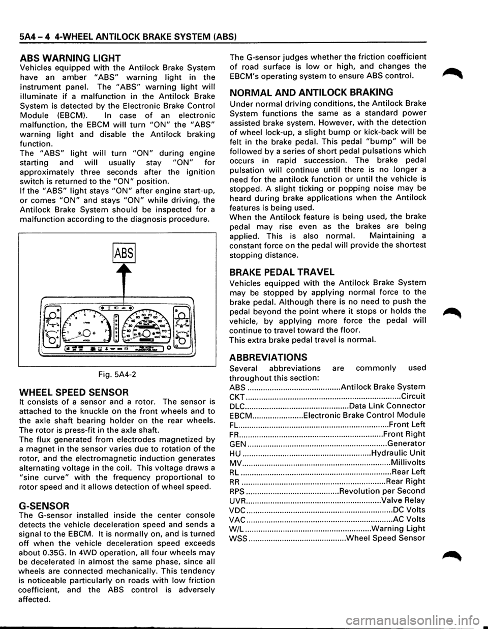
ABS WARNING LIGHT
Vehicles equipped with the Antilock Brake System
have an
amber "ABS" warning light in the
instrument panel. The "ABS" warning light will
illuminate if a malfunction in the Antilock Brake
System is detected by the Electronic Brake
Control
Module (EBCM). In case of an electronic
malfunction, the EBCM will turn "ON" the "ABS"
warning light and disable the Antilock braking
function.
The
"ABS" light will turn "ON" during engine
starting and
will usually stay "ON" for
approximately three seconds after the ignition
switch is returned to the "ON" position.
If the "ABS" light stays "ON" after engine start-up,
or comes "ON" and stays "ON" while driving, the
Antilock Brake System should be inspected
for a
malfunction according to the diagnosis procedure.
Fig. 5A4-2
WHEEL SPEED SENSOR
It consists of a sensor and a rotor. The sensor is
attached
to the knuckle on the front wheels and to
the axle shaft bearing holder on the rear wheels.
The
rotor is press-fit in the axle shaft.
The
flux generated from electrodes magnetized by
a magnet in the sensor varies due to rotation of the
rotor, and the electromagnetic
induction generates
alternating voltage in
the coil. This voltage draws a
"sine curve" with the frequency proportional to
rotor speed and it allows detection of wheel speed.
G-SENSOR
The G-sensor installed inside the center console
detects the vehicle deceleration speed and sends a
signal
to the EBCM. It is normally on, and is turned
off when the vehicle deceleration speed exceeds
about 0.35G.
In 4WD operation, all four wheels may
be decelerated in almost the same phase, since all
wheels are connected mechanically. This tendency
is noticeable particularly on roads
with low friction
coefficient, and the
ABS control is adversely
affected. The
G-sensor judges
whether the friction coefficient
of road surface is low or high, and changes the
EBCM's operating system to ensure ABS control.
NORMAL AND ANTILOCK BRAKING
Under normal driving conditions, the Antilock Brake
System functions the same
as a standard power
assisted brake system. However, with the detection
of wheel lock-up, a slight bump or kick-back will be
felt in the brake pedal. This pedal
"bump" will be
followed by a series of short pedal pulsations which
occurs in rapid succession. The brake pedal
pulsation
will continue until there is no longer a
need
for the antilock function or until the vehicle is
stopped. A
slight ticking or popping noise may be
heard
during brake applications when the Antilock
features is being used.
When the
Antilock feature is being used, the brake
pedal
may rise even as the brakes are being
applied. This is also
normal. Maintaining a
constant force on the pedal
will provide the shortest
stopping distance.
BRAKE PEDAL TRAVEL
Vehicles equipped with the Antilock Brake System
may be stopped by applying normal force to the
brake pedal.
Although there is no need to push the
pedal beyond the
point where it stops or holds the ~
vehicle, by applying more force the pedal will
continue to travel toward the floor.
This extra brake pedal travel is normal.
ABBREVIATIONS
Several abbreviations are commonly used
throughout this section:
ABS .......................................... Antilock Brake System
CKT ...................................................................... Circuit
DLC ............................................... Data Link Connector
EBCM ....................... Eiectronic Brake Control Module
FL. ................................................................... Front Left
FR ................................................................. Front Right
GEN ............................................................... Generator
HU .......................................................... Hydraulic Unit
MV ................................................................... Millivolts
RL .................................................................... Rear Left
RR ................................................................. Rear Right
RPS .......................................... Revolution per Second
UVR ............................................................. Valve Relay
VDC .................................................................. DC Volts
VAC .................................................................. AC Volts
W/L .........................................................
Warning Light
WSS ............................................ Wheel Speed Sensor
Page 416 of 1928
5A4-6 4-WHEEL ANTILOCK BRAKE SYSTEM (ABS)
If only rear wheels are rotated using jacks or
drum tester, the system will diagnose a speed
sensor
malfunction and the "ABS" warning
light will illuminate. But actually no trouble
exists. After inspection stop the engine once
and re-start it,
then make sure that the "ABS"
warning light does not illuminate.
If the battery has been discharged
The engine may stall if the battery has been
completely discharged and the engine is started via
a
jumper cable. This is because the Antilock Brake
System (ABS) requires a
large quantity of
electricity. In this case, wait until the battery is
recharged,
or set the ABS to a non-operative state
by removing the fuse for the ABS (40A). After the
battery has been recharged, stop the engine and
install the ABS fuse. Start the engine again, and
confirm that the ABS warning light does not light.
NOTE ON INTERMITTENTS
As with virtually any electronic system, it is difficult
to identify an intermittent failure. In such a case
duplicating the system malfunction during a test
drive
or a good description of vehicle behavior from
the customer may be helpful in locating a "most
likely" failed component or circuit. The symptom
diagnosis chart may also be useful in isolating the
failure. Most intermittent problems are caused by
faulty electrical connections or wiring. When an
intermittent failure is encountered, check suspect
circuits for:
Suspected harness damage.
• Poor mating of connector halves or terminals
not fully seated in the connector body (backed
out).
Improperly formed or damaged terminals.
TEST DRIVING ABS COMPLAINT
VEHICLES
In case that there has been an abnormality in the
lighting pattern of "ABS" warning light, the fault
can be located in accordance with the "DIAGNOSIS
BY 'ABS' WARNING LIGHT ILLUMINATION
PATTERN". In case of such trouble as can be
detected
by the driver as a vehicle symptom,
however, it is necessary to give a test drive
following the test procedure mentioned below,
thereby reproducing the symptom for trouble
diagnosis on a symptom basis:
1. Start the engine and make sure that the "ABS"
W/L goes OFF. If the W/L remains ON, it
means that the Diagnostic Trouble Code (DTC)
is stored. Therefore, read the code and
locate
the fault.
2. Start the vehicle and accelerate to 30 km/h (19
mph) or more.
3. Slowly brake and stop the vehicle completely.
4. Then restart the vehicle and accelerate to 40
km/h (25 mph) or more.
5. Brake at a time so as to actuate the ABS and ... ~
stop the vehicle.
6. Be cautious of abnormality during the test. If
theW/Lis actuated while driving, read the DTC
and locate the fault.
7. If the abnormality is not reproduced by the
test, make best efforts
to reproduce the
situation reported
by the customer.
8. If the abnormality has been detected, repair in
accordance
with the "SYMPTOM DIAGNOSIS".
NOTE:
Be sure to give a test drive on a wide, even
road
with a small traffic.
If an abnormality is detected, be sure to
suspend the test and start
trouble diagnosis at
once.
II ABS" WARNING LIGHT
When ABS trouble occurs to actuate "ABS"
warning light, the trouble code corresponding to
the trouble is stored in the EBCM. Only ordinary
brake is available with ABS being unactuated. Even
when "ABS" warning light is actuated, if the starter
switch is set
ON after setting it OFF once, the EBCM
checks
up on the entire system and, if there is no
abnormality, judges ABS to work currently and the
warning light is lit normally even though the
trouble code is stored.
NOTE:
Illumination of the "ABS" warning light
indicates that antilock braking is no longer
available. Power assisted braking without
antilock control is still available.
NORMAL OPERATION
II ABS" WARNING LIGHT
When the ignition is first moved from "OFF" to
"RUN", the amber "ABS" warning light will turn
"ON". The "ABS" warning light will turn "ON"
during engine starting and will usually stay "ON"
for approximately three seconds after the ignition
switch is returned to the "ON" position. The
warning light should remain "OFF" at all other
times.
•
Page 420 of 1928
5A4-10 4-WHEEL ANTILOCK BRAKE SYSTEM (ABS)
TECH 1 TOOL
TECH 1 is an effective tool for the diagnosis of
electrical fault of Antilock Brake System (ASS) and
system check.
Although you can completely
diagnose the system without a TECH 1, using the
tool is quicker. In the following procedures, the
!TECH 11 symbol shows where the TECH 1 is used.
The
t::nettll symbol means the tool is not used.
1. WHAT CAN BE DONE WITH TECH 1
ON TECH 1
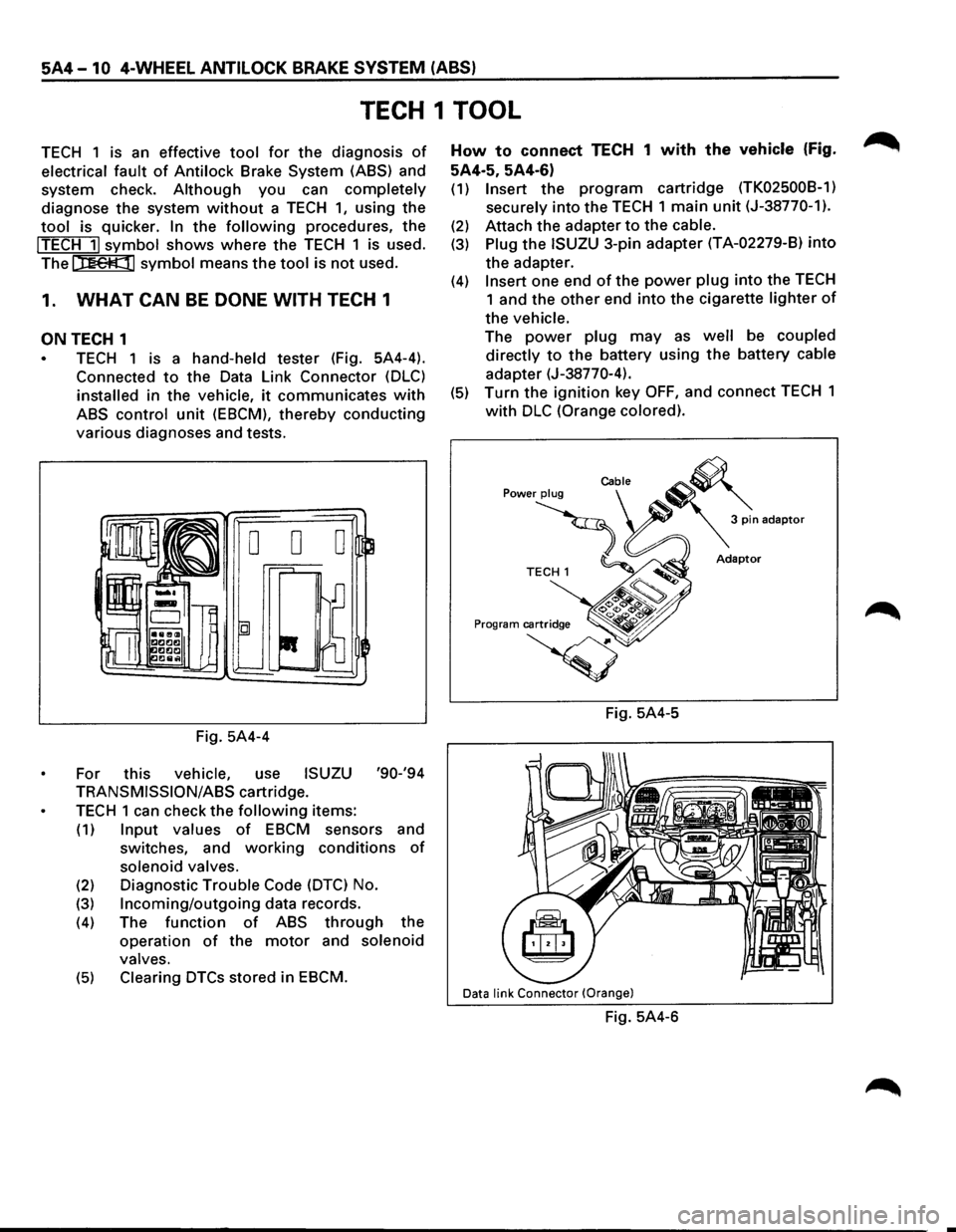
TECH 1 is a hand-held tester (Fig. 5A4-4).
Connected
to the Data Link Connector (DLC)
installed in the vehicle, it communicates with
ABS control unit (EBCM), thereby conducting
various diagnoses and tests.
Fig. 5A4-4
For this
vehicle, use ISUZU '90-'94
TRANSMISSION/ASS cartridge.
TECH 1 can check the following items:
(1) Input values of EBCM sensors and
switches, and
working conditions of
solenoid valves.
(2) Diagnostic Trouble Code (DTC) No.
(3) Incoming/outgoing data records.
(4) The function of ABS through the
operation
of the motor and solenoid
valves.
(5) Clearing DTCs stored in EBCM.
How to connect TECH 1 with the vehicle (Fig.
5A4·5, 5A4-6)
(1) Insert the program cartridge (TK02500B-1)
securely
into the TECH 1 main unit (J-38770-1).
(2) Attach the adapter to the cable.
(3) Plug the ISUZU 3-pin adapter (T A-02279-8) into
the adapter.
(4) Insert one end of the power plug into the TECH
1 and the other end into the cigarette lighter of
the vehicle.
The power plug may as well be coupled
directly
to the battery using the battery cable
adapter (J-38770-4).
(5) Turn the ignition key OFF, and connect TECH 1
with DLC (Orange colored).
Fig. 5A4-5
Data link Connector (Orange)
Fig. 5A4-6
Page 423 of 1928
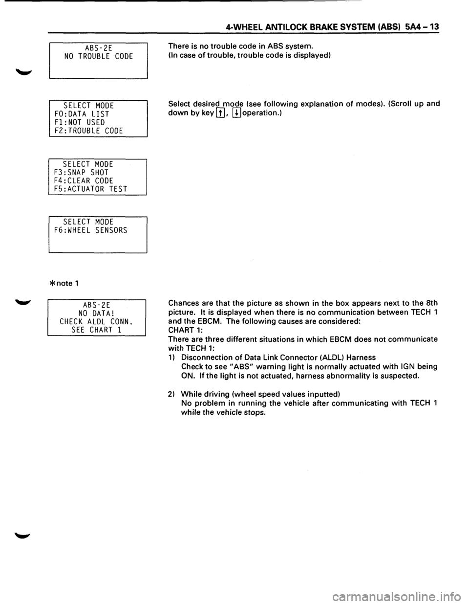
ABS-2E
NO TROUBLE CODE
SELECT MODE
FO:DATA LIST
F1: NOT USED
F2:TROUBLE CODE
SELECT MODE
F3:SNAP SHOT
F4:CLEAR CODE
F5:ACTUATOR TEST
SELECT MODE
F6:WHEEL SENSORS
*note 1
ABS-2E
NO DATA!
CHECK ALDL CONN.
SEE CHART 1
4-WHEEL ANTILOCK BRAKE SYSTEM (ABS) 5A4-13
There is no trouble code in ABS system.
(In case of trouble, trouble code is displayed)
Select
desired mode (see following explanation of modes). (Scroll up and
down by key III. m operation.)
Chances are
that the picture as shown in the box appears next to the 8th
picture.
It is displayed when there is no communication between TECH 1
and the EBCM. The
following causes are considered:
CHART
1:
There are three different situations in which EBCM does not communicate
with TECH 1:
1) Disconnection of Data Link Connector (ALDL) Harness
Check
to see "ABS" warning light is normally actuated with IGN being
ON. lfthe light is not actuated, harness abnormality is suspected.
2) While driving (wheel speed values inputted)
No problem in running the vehicle after communicating with TECH 1
while the vehicle stops.
Page 425 of 1928
4-WHEEL ANTILOCK BRAKE SYSTEM (ABS) 5A4-15
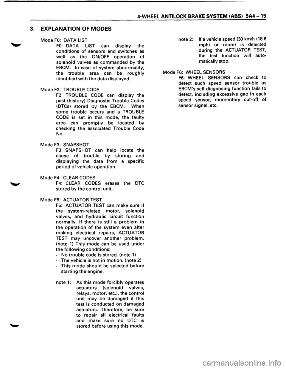
3. EXPLANATION OF MODES
Mode FO: OAT A LIST
FO: DATA LIST can display the
conditions
of sensors and switches as
well as the ONfOFF operation of
solenoid valves as commanded by the
EBCM.
In case of system abnormality,
the trouble area can be roughly
identified
with the data displayed.
Mode
F2: TROUBLE CODE
F2: TROUBLE CODE can display the
past (history) Diagnostic Trouble Codes
(DTCs) stored
by the EBCM. When
some
trouble occurs and a TROUBLE
CODE is set in this mode, the faulty
area can
promptly be located by
checking the associated Trouble Code
No.
Mode
F3: SNAPSHOT
F3: SNAPSHOT can help locate the
cause
of trouble by storing and
displaying the data
from a specific
period
of vehicle operation.
Mode
F4: CLEAR CODES
F4: CLEAR CODES erases the DTC
stored by the control unit.
Mode F5: ACTUATOR TEST
F5: ACTUATOR TEST can make sure if
the system-related motor, solenoid
valves, and hydraulic circuit function
normally. If there is still a problem in
the operation of the system even after
making electrical repairs, ACTUATOR
TEST may uncover another problem.
(note
1) This mode can be used under
the
following conditions:
No
trouble code is stored. (note 1)
The vehicle is not in motion. (note 2)
This mode should be selected before
starting the engine.
note
1: As this mode forcibly operates
actuators (solenoid valves,
relays, motor, etc.), the control
unit may be damaged if this
test
is conducted on damaged
actuators. Therefore, be sure
to repair all electrical faults
and make sure no
DTC is
stored before using this mode. note
2: If a vehicle speed (30 km/h
(18.6
mph)
or more) is detected
during the ACTUATOR
TEST,
the test function will auto
matically stop.
Mode
F6: WHEEL SENSORS
F6: WHEEL SENSORS can check to
detect such speed sensor trouble as
EBCM's self-diagnosing function fails to
detect, including excessive gap in each
speed sensor,
momentary cut-off of
sensor signal, etc.