brake sensor ISUZU TROOPER 1995 Service Manual
[x] Cancel search | Manufacturer: ISUZU, Model Year: 1995, Model line: TROOPER, Model: ISUZU TROOPER 1995Pages: 1928
Page 426 of 1928
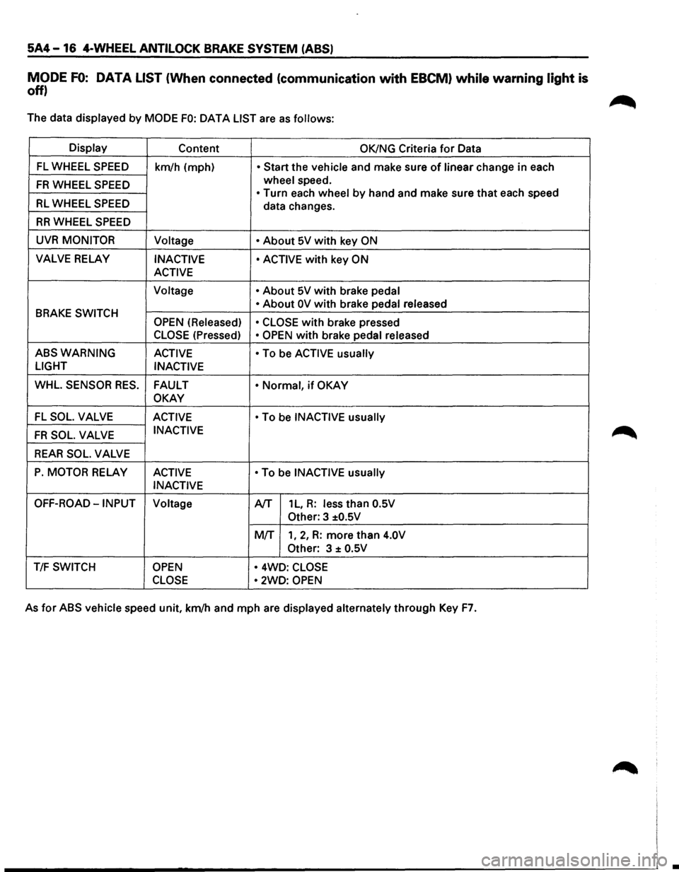
5A4-16 4-WHEEL ANTILOCK BRAKE SYSTEM (ABS)
MODE FO: DATA LIST (When connected (communication with EBCM) while warning light is
off)
The data displayed by MODE FO: OAT A LIST are as follows:
Display Content OK/NG Criteria for Data
FL WHEEL SPEED km/h (mph) • Start the vehicle and make sure of linear change in each
FR WHEEL SPEED wheel speed.
• Turn each wheel by hand and make sure that each speed RL WHEEL SPEED data changes.
RR WHEEL SPEED
UVR MONITOR
Voltage • About 5V with key ON
VALVE RELAY INACTIVE • ACTIVE with key ON
ACTIVE
Voltage •
About 5V with brake pedal
BRAKE SWITCH • About OV with brake pedal
released
OPEN (Released)
• CLOSE
with brake pressed
CLOSE (Pressed) • OPEN with brake pedal released
ABSWARNING ACTIVE
• To be ACTIVE usually
LIGHT
INACTIVE
WHL. SENSOR RES. FAULT • Normal, if OKAY
OKAY
-FL SOL. VALVE ACTIVE • To be INACTIVE usually
FR SOL. VALVE INACTIVE
REAR SOL. VALVE
P. MOTOR RELAY ACTIVE • To be INACTIVE usually
INACTIVE
OFF-ROAD-INPUT Voltage A/T 1 L, R: less than O.SV
Other: 3 ±O.SV
MIT 1, 2, R: more than 4.0V
Other:
3 ± O.SV
T/F SWITCH OPEN • 4WD: CLOSE
CLOSE •
2WD: OPEN
As for ABS vehicle speed unit, km/h and mph are displayed alternately through Key F7.
•
Page 427 of 1928
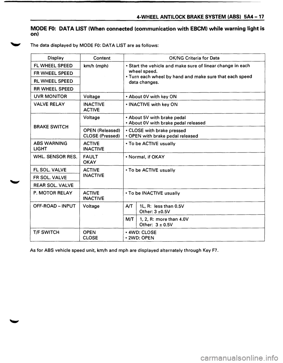
4-WHEEL ANTILOCK BRAKE SYSTEM (ABS) 5A4-17
MODE FO: DATA LIST (When connected (communication with EBCM) while warning light is
on)
._,. The data displayed by MODE FO: DATA LIST are as follows:
Display
Content OK/NG Criteria for Data
FL WHEEL SPEED
km/h (mph) • Start the vehicle and make sure of linear change in each
FR WHEEL SPEED wheel speed.
• Turn each wheel by hand and make sure that each speed RL WHEEL SPEED data changes.
RR WHEEL SPEED
UVR MONITOR Voltage • About OV with key ON
VALVE RELAY INACTIVE • INACTIVE with key ON
ACTIVE
Voltage • About 5V with brake pedal
BRAKE
SWITCH • About OV with brake
pedal released
OPEN (Released) • CLOSE with brake pressed
CLOSE (Pressed) • OPEN with brake pedal released
ABSWARNING ACTIVE • To be ACTIVE usually
LIGHT
INACTIVE
WHL.
SENSOR RES. FAULT • Normal, if OKAY
OKAY
FL SOL. VALVE ACTIVE • To be ACTIVE usually
FR SOL. VALVE INACTIVE
REAR SOL. VALVE
P. MOTOR RELAY
ACTIVE • To be INACTIVE usually
INACTIVE
OFF-ROAD-INPUT Voltage A/T 1 L, R: less than 0.5V
Other:
3 ±0.5V
MIT
1, 2, R: more than 4.0V
Other:
3 ± 0.5V
T/F SWITCH OPEN • 4WD: CLOSE
CLOSE •
2WD: OPEN
As for ABS vehicle speed unit, km/h and mph are displayed alternately through Key F7.
Page 428 of 1928
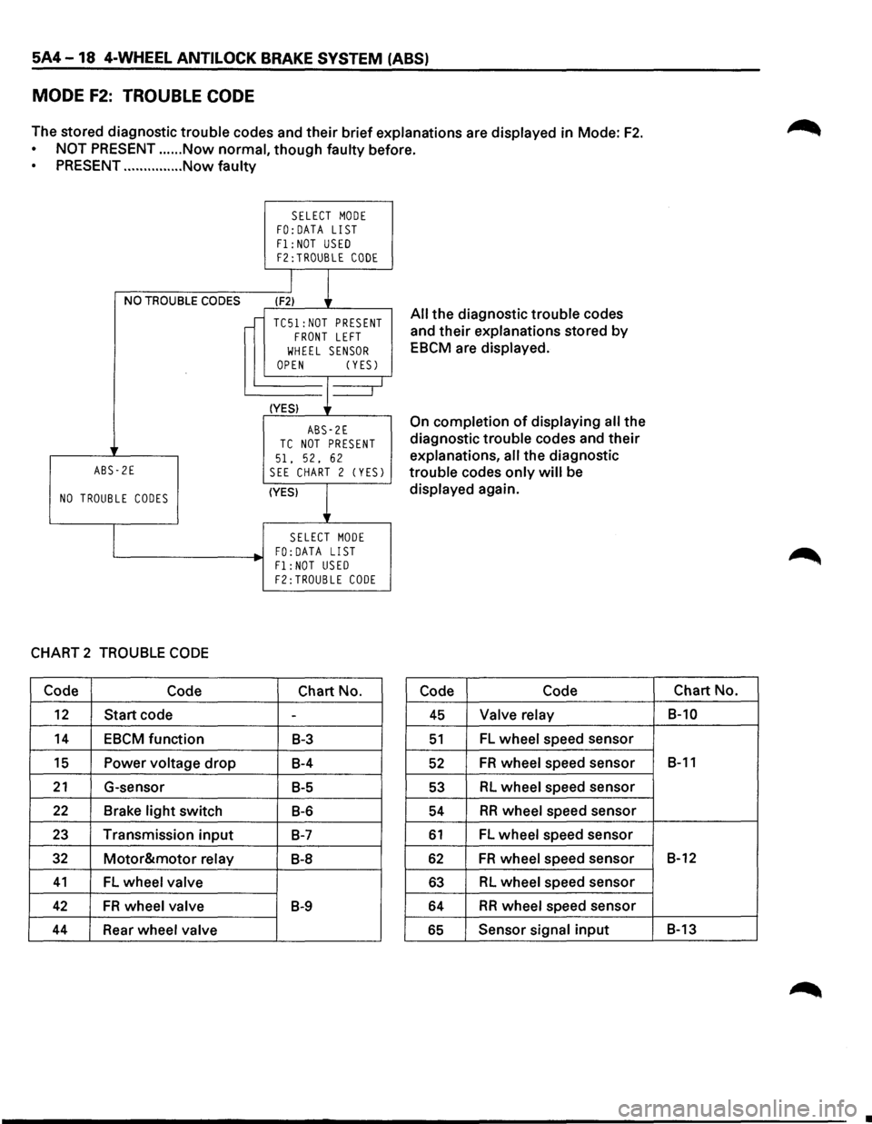
5A4-18 4-WHEEL ANTILOCK BRAKE SYSTEM (ABS)
MODE F2: TROUBLE CODE
The stored diagnostic trouble codes and their brief explanations are displayed in Mode: F2.
NOT PRESENT ...... Now normal, though faulty before.
PRESENT ............... Now faulty
NO TROUBLE CODES
ABS-2E
NO TROUBLE CODES
CHART 2 TROUBLE CODE
Code Code
12 Start code
14 EBCM function
15 Power voltage drop
21 G-sensor
22 Brake light switch
23 Transmission input
32 Motor&motor relay
41 FL wheel valve
42 FR wheel valve
44 Rear wheel valve
SELECT MODE FO:DATA LIST
F1: NOT USED F2:TROUBLE CODE
I
l (F2)
TC51:NOT PRESENT FRONT LEFT
WHEEL SENSOR OPEN (YESJ
(YES) J--_j
ABS-2E TC NOT PRESENT
51. 52, 62 SEE CHART 2 (YESJ
(YES)
l
SELECT MODE FO: DATA LIST
Fl:NOT USED F2:TROUBLE CODE
Chart No.
-
B-3
B-4
B-5
B-6
B-7
B-8
B-9
All the diagnostic trouble codes
and
their explanations stored by
EBCM are displayed.
On completion of displaying all the
diagnostic trouble codes and
their
explanations, all the diagnostic
trouble codes
only will be
displayed again.
Code Code
45 Valve relay
51 FL wheel speed sensor
52 FR wheel speed sensor
53 RL wheel speed sensor
54 RR wheel speed sensor
61 FL wheel speed sensor
62 FR wheel speed sensor
63 RL wheel speed sensor
64 RR wheel speed sensor
65 Sensor signal input
Chart No.
B-10
B-11
B-12
B-13
•
Page 441 of 1928
4-WHEEL ANTILOCK BRAKE SYSTEM (ABS) 5A4-31
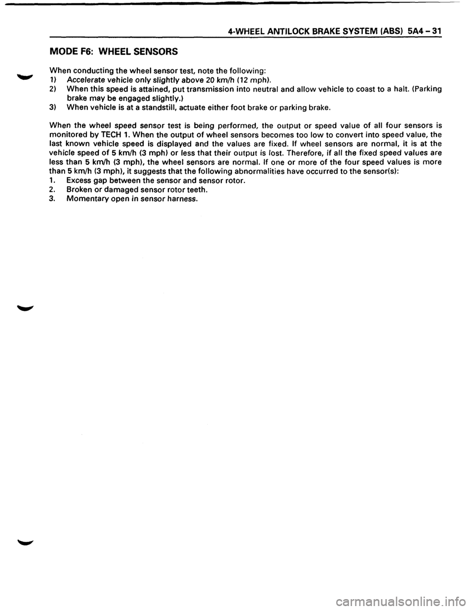
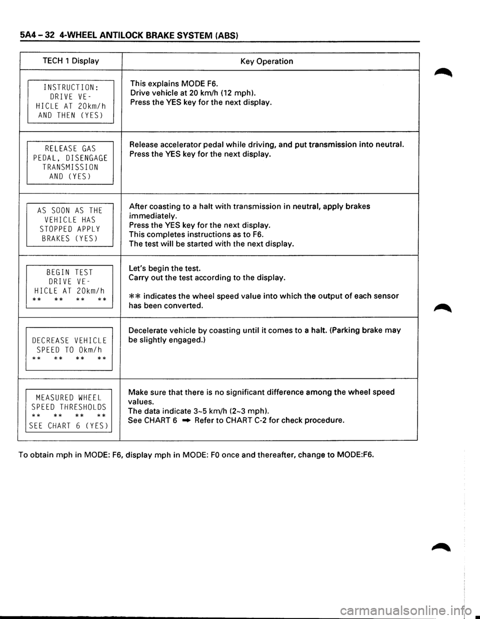
MODE F6: WHEEL SENSORS
When conducting the wheel sensor test, note the following:
1) Accelerate vehicle only slightly above 20 km/h (12 mph).
2) When this speed is attained, put transmission into neutral and allow vehicle to coast to a halt. (Parking
brake may be engaged slightly.)
3) When vehicle is at a standstill, actuate either foot brake or parking brake.
When the
wheel speed sensor test is being performed, the output or speed value of all four sensors is
monitored
by TECH 1. When the output of wheel sensors becomes too low to convert into speed value, the
last known vehicle speed is displayed and the values are fixed. If wheel sensors are normal, it is at the
vehicle speed
of 5 km/h (3 mph) or less that their output is lost. Therefore, if all the fixed speed values are
less than 5 km/h (3 mph), the wheel sensors are normal. If one or more of the four speed values is more
than 5 km/h
(3 mph), it suggests that the following abnormalities have occurred to the sensor(s):
1. Excess gap between the sensor and sensor rotor.
2. Broken or damaged sensor rotor teeth.
3. Momentary open in sensor harness.
Page 442 of 1928
5A4-32 4-WHEEL ANTI LOCK BRAKE SYSTEM (ABS)
TECH 1 Display Key Operation
INSTRUCT I ON: This explains MODE F6.
DRIVE VE-Drive vehicle at 20 km/h (12 mph).
HICLE AT 20km/h Press the YES key for the next display.
AND THEN (YES)
RELEASE GAS Release accelerator pedal while driving, and put transmission into neutral.
PEDAL, DISENGAGE Press the YES key for the next display.
TRANSMISSION
AND (YES)
AS SOON AS THE After coasting to a halt with transmission in neutral, apply brakes
VEHICLE HAS immediately.
STOPPED APPLY Press the YES key for the next display.
BRAKES (YES) This completes instructions as to F6.
The test will be started with the next display.
BEGIN TEST Let's begin the test.
DRIVE VE-Carry out the test according to the display.
HICLE AT 20km/h ** indicates the wheel speed value into which the output of each sensor ** ** ** ** has been converted.
Decelerate vehicle by coasting until it comes to a halt. (Parking brake may
DECREASE VEHICLE be slightly engaged.)
SPEED TO Okm/h
** ** ** **
MEASURED WHEEL Make sure that there is no significant difference among the wheel speed
SPEED THRESHOLDS values.
** **
** ** The
data indicate 3-5 km/h (2-3 mph).
SEE CHART 6 (YES) See CHART 6 .. Refer to CHART C-2 for check procedure.
To obtain mph in
MODE: F6, display mph in MODE: FO once and thereafter, change to MODE:F6.
Page 443 of 1928
4-WHEEL ANTILOCK BRAKE SYSTEM (ABS) 5A4-33
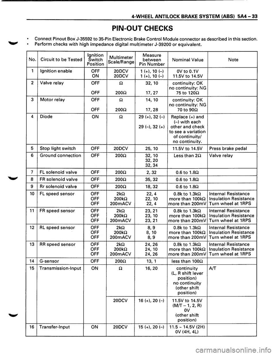
PIN-OUT CHECKS
Connect Pinout Box J-35592 to 35-Pin Electronic Brake Control Module connector as described in this section.
~ Perform checks with high impedance digital multimeter J-39200 or equivalent.
Ignition
Multi meter Measure
No. Circuit to be Tested
Switch Scale/Range between Nominal Value Note Position
Pin Number
1 Ignition enable OFF 20DCV 1 (+), 10 (-) OV to 0.1V
ON 20DCV
1 (+), 10 (-) 11.5Vto 14.5V
2
Valve relay OFF n 32, 10 continuity: OK
no continuity: NG
OFF 200.Q 17,27 75 to 120n
3 Motor relay OFF n 14, 10 continuity: OK
no continuity: NG
OFF 200Q 17,28 70 to 90n
4
Diode ON n 29 (+), 32 (-) Replace(+) and
(-)with each
29 (-), 32 (+) other and check
to see a variation
of continuity/
no continuity.
5
Stop light switch OFF 20DCV 25, 10 11.5V to 14.5V Press brake pedal
6 Ground connection OFF 200Q 32, 10 Less than 2.Q Valve relay
32,20
32,34
7 FL solenoid valve OFF 200Q 2,32 0.6 to 1.8Q
8 FR solenoid valve OFF 200Q 35,32 0.6 to 1.8n
9 Rr solenoid valve OFF 200Q 18,32 0.6 to 1.8n
10 FL speed sensor OFF 2k.Q 22,4 0.8k to 1.3kn Internal Resistance
OFF 200k.Q 22, 10 more than 100kn Insulation Resistance
OFF 200mACV 22,4 more than 200mV Turn wheel at 1RPS
11 FR speed
sensor OFF 2k.Q 23,21 0.8k to 1.3k.Q Internal Resistance
OFF 200k.Q 23, 10 more than 100k.Q Insulation Resistance
OFF 200mACV 23,21 more than 200mV Turn wheel at 1RPS
12 RL speed sensor OFF 2k.Q 8,9 0.8k to 1.3k.Q Internal Resistance
OFF 200k.Q 8, 10 more than 100k.Q Insulation Resistance
OFF 200mACV 8,9 more than 200mV Turn wheel at 1RPS
13 RR speed sensor OFF 2k.Q 24,26 0.8k to 1.3k.Q Internal Resistance
OFF 200k.Q 24, 10 more than 100k.Q Insulation Resistance
OFF 200mACV 24,26 more than 200mV Turn wheel at 1RPS
14 G-sensor OFF 200.Q 13, 1 less than 100n
15 Transmission-Input ON n 16,20 continuity A/T
(L, R shift lever
position)
no
continuity
(other shift
position)
20DCV 16 (+), 20 (-) 11.5V to 14.5V
(M/T-1, 2, R)
ov
(other shift
position)
16 Transfer-Input ON 20DCV 15 (+), 20 (-) 11.5-14.5V (2H)
OV (4H, 4L)
Page 447 of 1928
!! co U1 )> "" I .... w
(
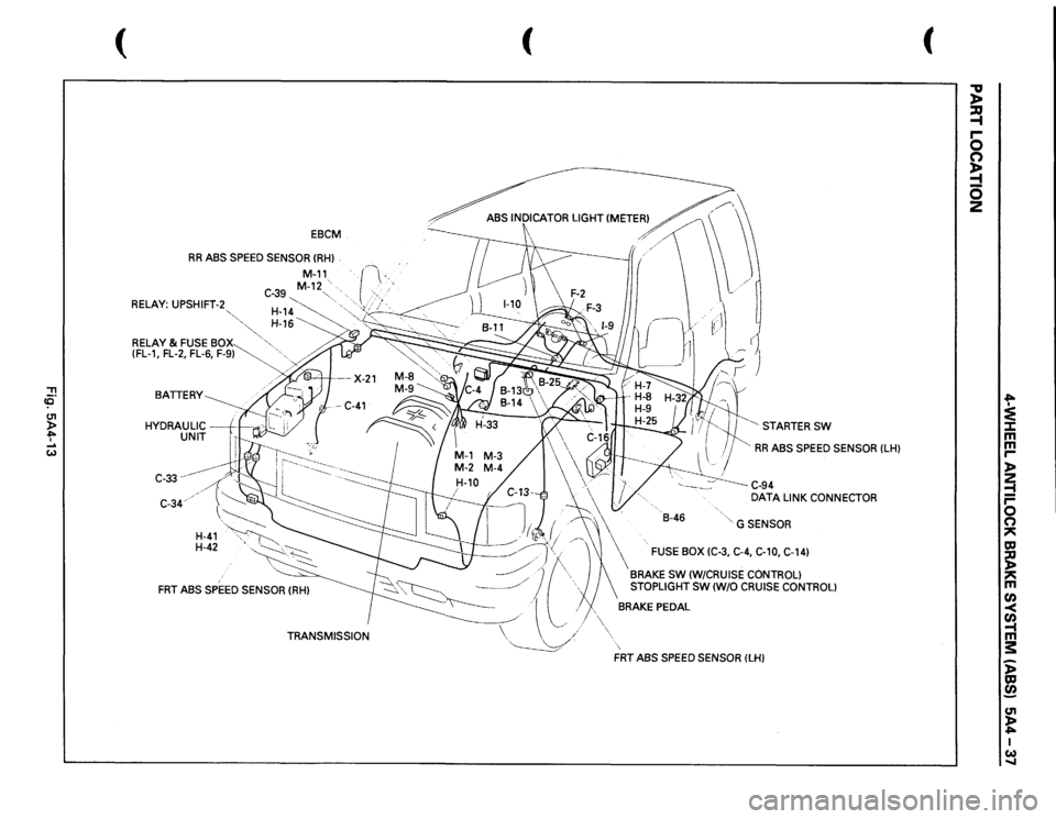
EBCM
RR
ABS SPEED SENSOR
(RHl
.
RELAY:
UPSHIFT-2
""·,'-....."
M-11_
. ·r·---
..
C-39
M-12"-~.·
··..
> .. , ,·
~'
...
,
~~~~~
~.-·
& FUSE
BOX
· ••.
(FL-1,
FL-2, FL-6,
F-9~
'•
BATTERY HYDRAULIC
--+1--.-.
UNIT
C-33
--~----
C-34.
H-41
H-42
TRANSMISSION
(
~·~ rl r
( STARTER
SW
RR
ABS SPEED SENSOR
(LH)
\~· \'
-.
.
B-46
' G SENSOR
\
FUSE
BOX (C-3, C-4, C-10, C-14)
BRAKE
SW
(W/CRUISE CONTROL)
STOPLIGHT SW
(W/0
CRUISE CONTROL)
BRAKE PEDAL FRT
ABS
SPEED SENSOR
(LH)
(
"V )> ~ r-0 s 5 2
.... :e ::I: m
m r-l> 2 ~ r-0 0 ~ CCI ~ ~ m ~ Cl) -t m s: ~ ~ c.n t I w .....
Page 449 of 1928
4-WHEEL ANTILOCK BRAKE SYSTEM (ABS) 5A4-39
CHART A-1 [):Eeft:j]
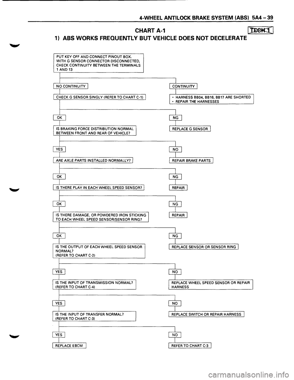
1) ABS WORKS FREOUENTL V BUT VEHICLE DOES NOT DECELERATE
PUT KEY OFF AND CONNECT PINOUT BOX.
WITH G SENSOR CONNECTOR DISCONNECTED,
CHECK CONTINUITY BETWEEN THE TERMINALS 1 AND 13
CHECK G SENSOR SINGLY (REFER TO CHART C-1)
IS THERE DAMAGE, OR POWDERED IRON STICKING
TO EACH WHEEL SPEED SENSOR/SENSOR RING?
IS
THE OUTPUT OF EACH WHEEL SPEED SENSOR
NORMAL?
(REFER TO CHART C-2)
• HARNESS BB04, BB16, BB17 ARE SHORTED
• REPAIR THE HARNESSES
REPLACE WHEEL SPEED
SENSOR OR REPAIR HARNESS
Page 450 of 1928
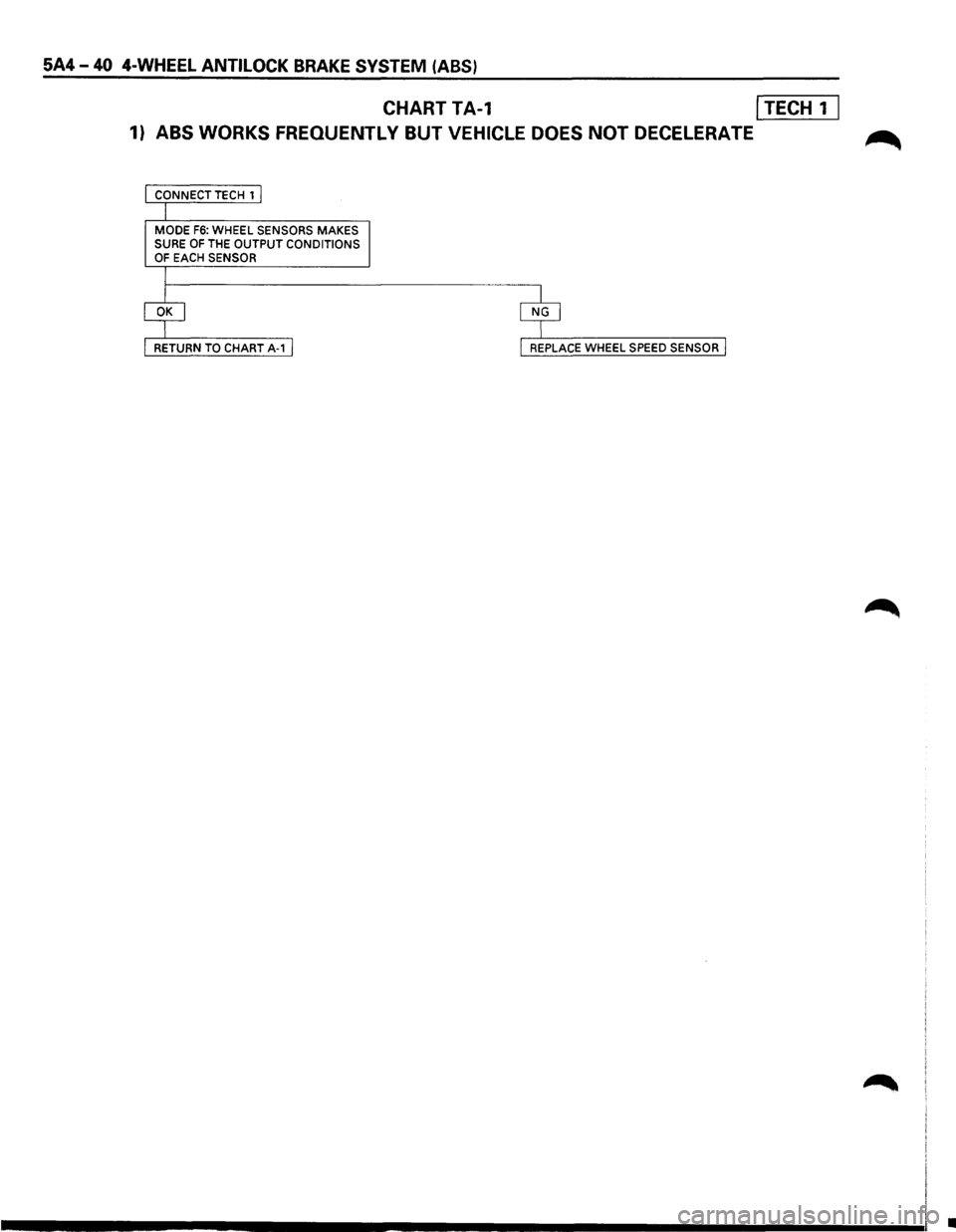
5A4-40 4-WHEEL ANTILOCK BRAKE SYSTEM (ABS)
CHART TA-1 I TECH 1 I
1) ABS WORKS FREOUENTL Y BUT VEHICLE DOES NOT DECELERATE ~
CONNECT TECH 1 I
I
MODE F6: WHEEL SENSORS MAKES SURE OF THE OUTPUT CONDITIONS OF EACH SENSOR
I
RETURN TO CHART A-1 I I REPLACE WHEEL SPEED SENSOR I
•
Page 452 of 1928
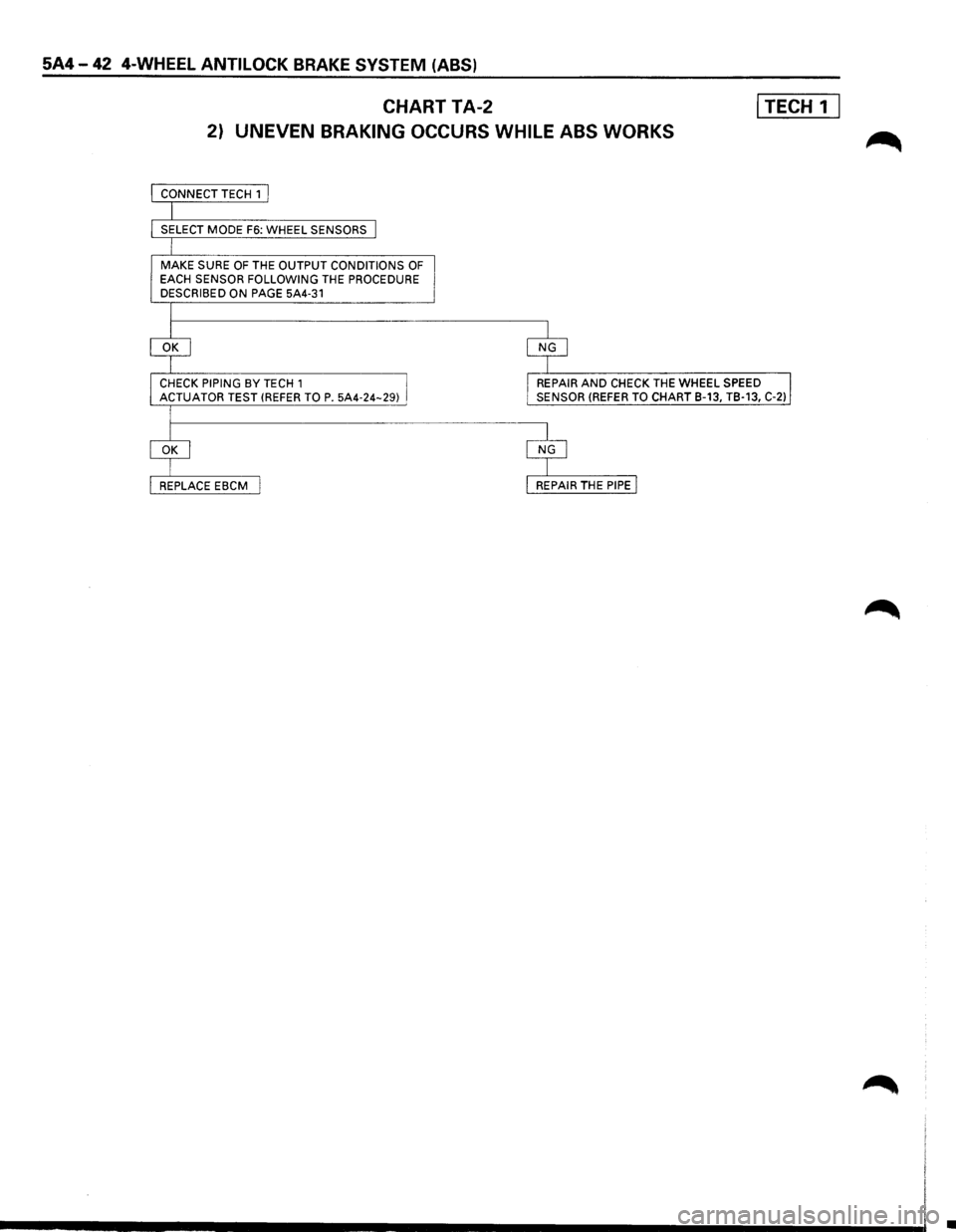
5A4-42 4-WHEEL ANTILOCK BRAKE SYSTEM (ABS)
CHART TA-2 I TECH 1 I
2) UNEVEN BRAKING OCCURS WHILE ABS WORKS
MAKE SURE OF THE OUTPUT CONDITIONS OF EACH SENSOR FOLLOWING THE PROCEDURE
DESCRIBED ON PAGE 5A4-31
REPAIR AND CHECK THE WHEEL SPEED
SENSOR (REFER TO CHART B-13, TB-13, C-2)
•