clutch ISUZU TROOPER 1995 Owner's Guide
[x] Cancel search | Manufacturer: ISUZU, Model Year: 1995, Model line: TROOPER, Model: ISUZU TROOPER 1995Pages: 1928
Page 507 of 1928
ENGINE DIAGNOSIS 6-9
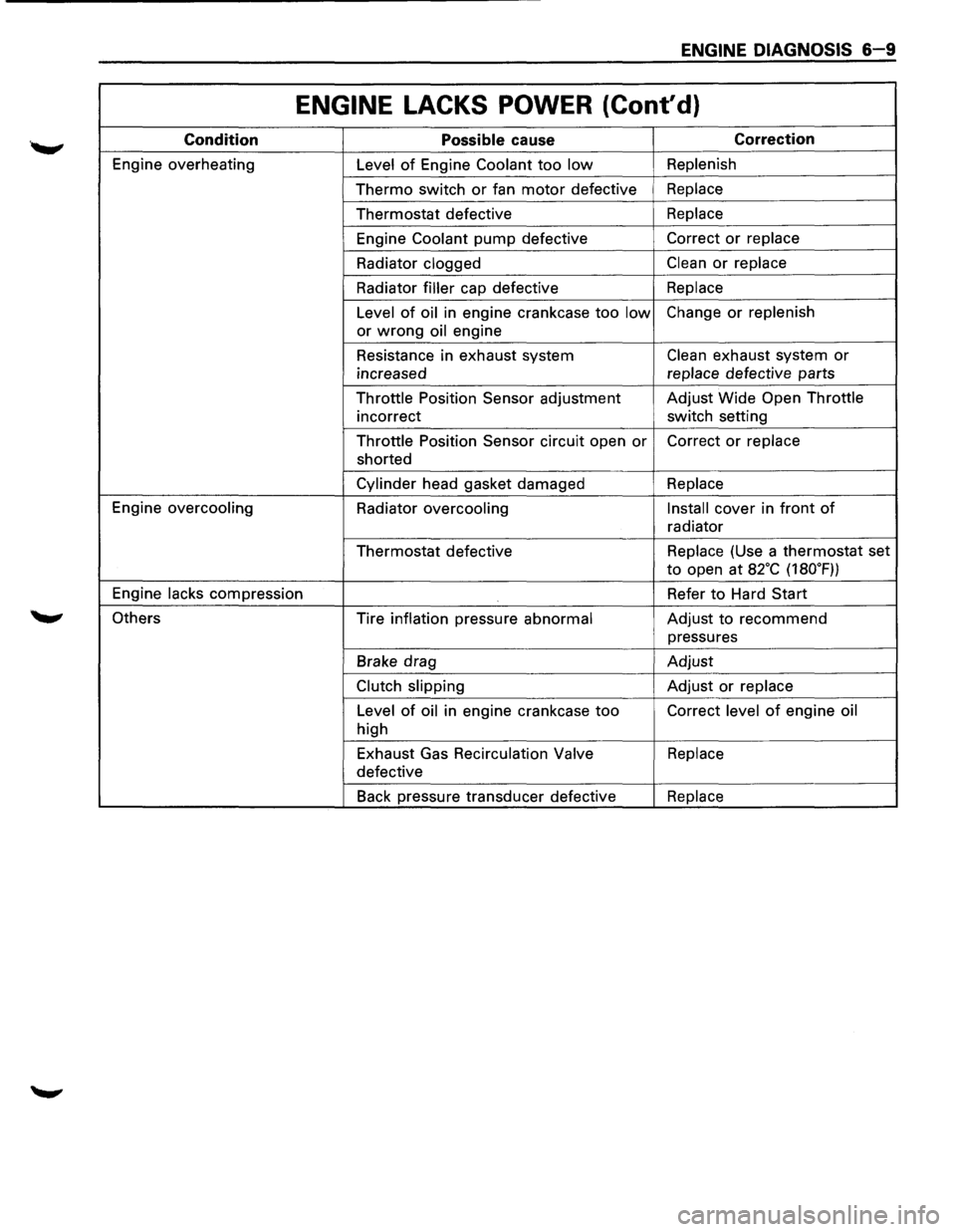
ENGINE LACKS POWER (Cont'd)
Condition Possible cause Correction
Engine overheating
Level of Engine Coolant too low Replenish
Thermo switch or fan motor defective Replace
Thermostat defective Replace
Engine
Coolant pump defective Correct or replace
Radiator clogged
Clean or replace
Radiator
filler cap defective Replace
Level
of oil in engine crankcase too low Change or replenish
or
wrong oil engine
Resistance in exhaust system
Clean exhaust system or
increased replace
defective parts
Throttle Position Sensor adjustment Adjust
Wide Open Throttle
incorrect switch setting
Throttle Position Sensor circuit open
or Correct or replace
shorted
Cylinder head gasket damaged Replace
Engine overcooling
Radiator
overcooling Install cover
in front of
radiator
Thermostat defective Replace
(Use a thermostat set
to open at a2·c (180.F))
Engine
lacks compression Refer to Hard Start
Others Tire inflation pressure
abnormal Adjust to recommend
pressures
Brake drag Adjust
Clutch slipping Adjust or replace
Level
of oil in engine crankcase too Correct level of engine oil
high
Exhaust Gas
Recirculation Valve Replace
defective
Back pressure transducer defective
Replace
Page 509 of 1928
ENGINE DIAGNOSIS 6-11
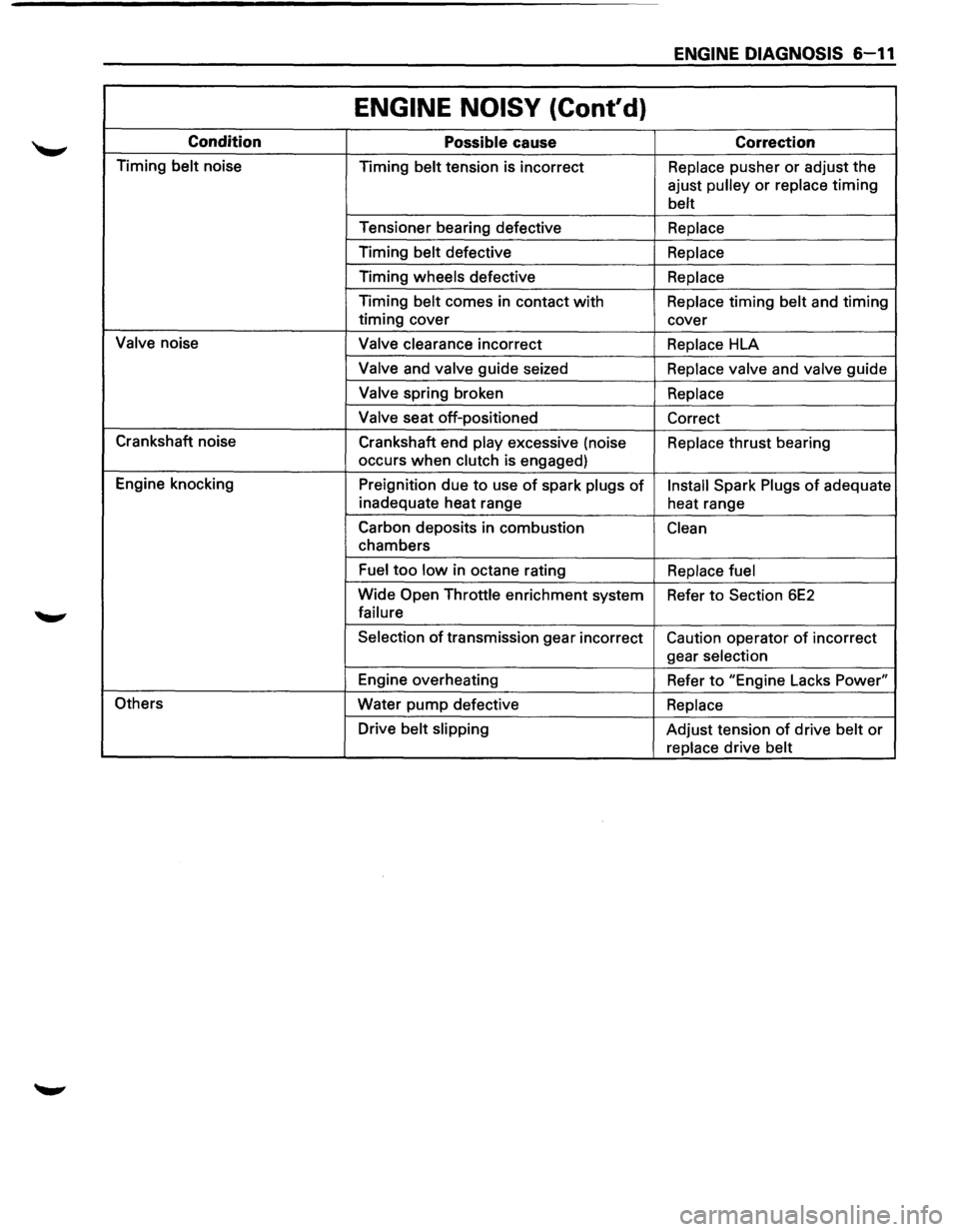
ENGINE NOISY (Cont'd)
Condition Possible cause Correction
Timing belt noise
Timing belt tension is incorrect Replace pusher or adjust the
ajust
pulley or replace timing
belt
Tensioner bearing defective Replace
Timing belt defective Replace
Timing wheels defective Replace
Timing belt comes in contact with Replace timing belt and timing
timing cover
cover
Valve noise Valve clearance incorrect Replace HLA
Valve and valve guide seized Replace valve and valve guide
Valve spring broken Replace
Valve
seat off-positioned
Correct
Crankshaft noise
Crankshaft end
play excessive (noise Replace thrust bearing
occurs
when clutch is engaged)
Engine knocking
Preignition due
to use of spark plugs of Install Spark Plugs of adequate
inadequate heat range
heat range
Carbon deposits in combustion
Clean
chambers
Fuel too low in octane rating Replace fuel
Wide Open Throttle enrichment system
Refer to Section 6E2
failure
Selection
of transmission gear incorrect Caution operator of incorrect
gear
selection
Engine overheating
Refer to "Engine Lacks Power"
Others Water
pump defective Replace
Drive belt slipping Adjust tension of drive belt or
replace drive belt
Page 512 of 1928
6-14 ENGINE DIAGNOSIS
1;:-
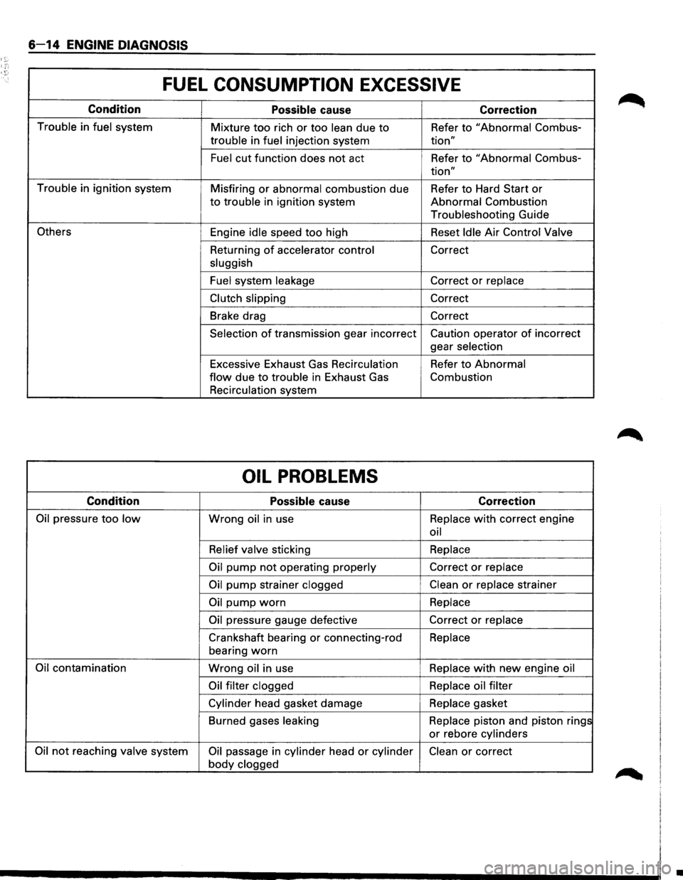
FUEL CONSUMPTION EXCESSIVE
Condition
Possible cause Correction
Trouble in fuel system
Mixture too rich or too lean due to Refer to "Abnormal Combus-
trouble in fuel injection system tion"
Fuel cut function does not act Refer to "Abnormal Combus-
tion"
Trouble in ignition system
Misfiring or abnormal combustion due Refer to Hard Start or
to trouble in ignition system Abnormal Combustion
Troubleshooting Guide
Others Engine idle speed too high Reset Idle Air Control Valve
Returning
of accelerator control Correct
sluggish
Fuel system leakage
Correct or replace
Clutch slipping Correct
Brake drag Correct
Selection of transmission gear incorrect Caution operator of incorrect
gear selection
Excessive Exhaust
Gas Recirculation Refer to Abnormal
flow due to trouble in Exhaust Gas Combustion
Recirculation system
OIL PROBLEMS
Condition
Possible cause Correction
Oil pressure too low Wrong oil in use Replace with correct
engine
oil
Relief valve sticking Replace
Oil pump not operating
properly Correct or replace
Oil pump strainer clogged Clean or replace strainer
Oil pump worn Replace
Oil pressure gauge defective Correct or replace
Crankshaft bearing or connecting-rod Replace
bearing
worn
Oil contamination Wrong oil in use Replace with new engine
oil
Oil filter clogged Replace oil filter
Cylinder head gasket damage Replace
gasket
Burned gases leaking Replace piston and piston rings
or rebore cylinders
Oil not reaching valve system Oil passage in cylinder head or cylinder Clean or correct
body clogged
•
Page 659 of 1928
CRANKING SYSTEM 6D2 - 1
SECTION 602
CRANKING SYSTEM
CONTENTS
General Description ....................... .
Diagnosis
.................................... .
On-Vehicle Service ........................ . 6D2-1
6D2-3
6D2-8 Unit
Repair.................................... 6D2-9
Main Data and Specifications
............ 6D2-17
Torque Specifications
...................... 6D2-18
GENERAL DESCRIPTION
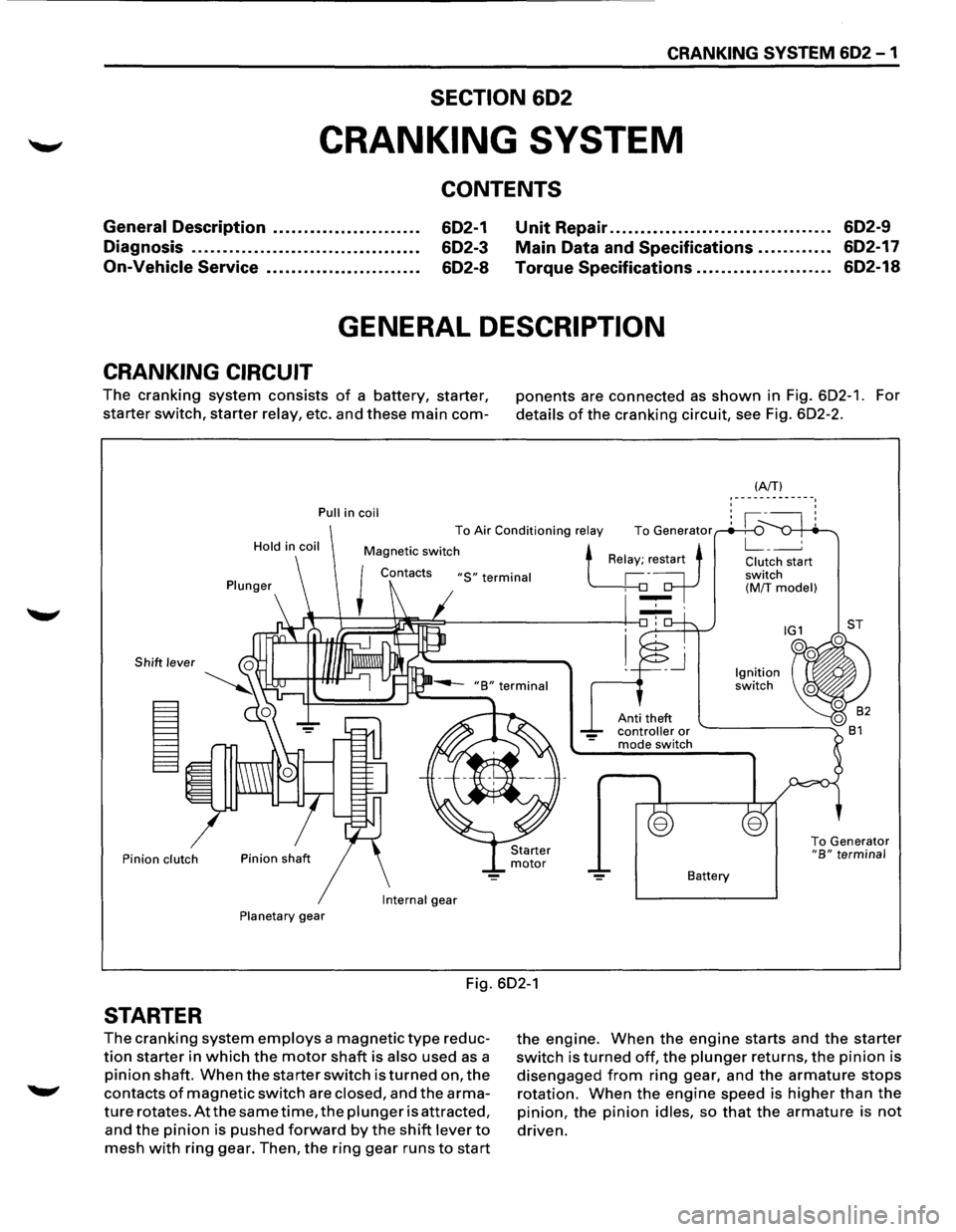
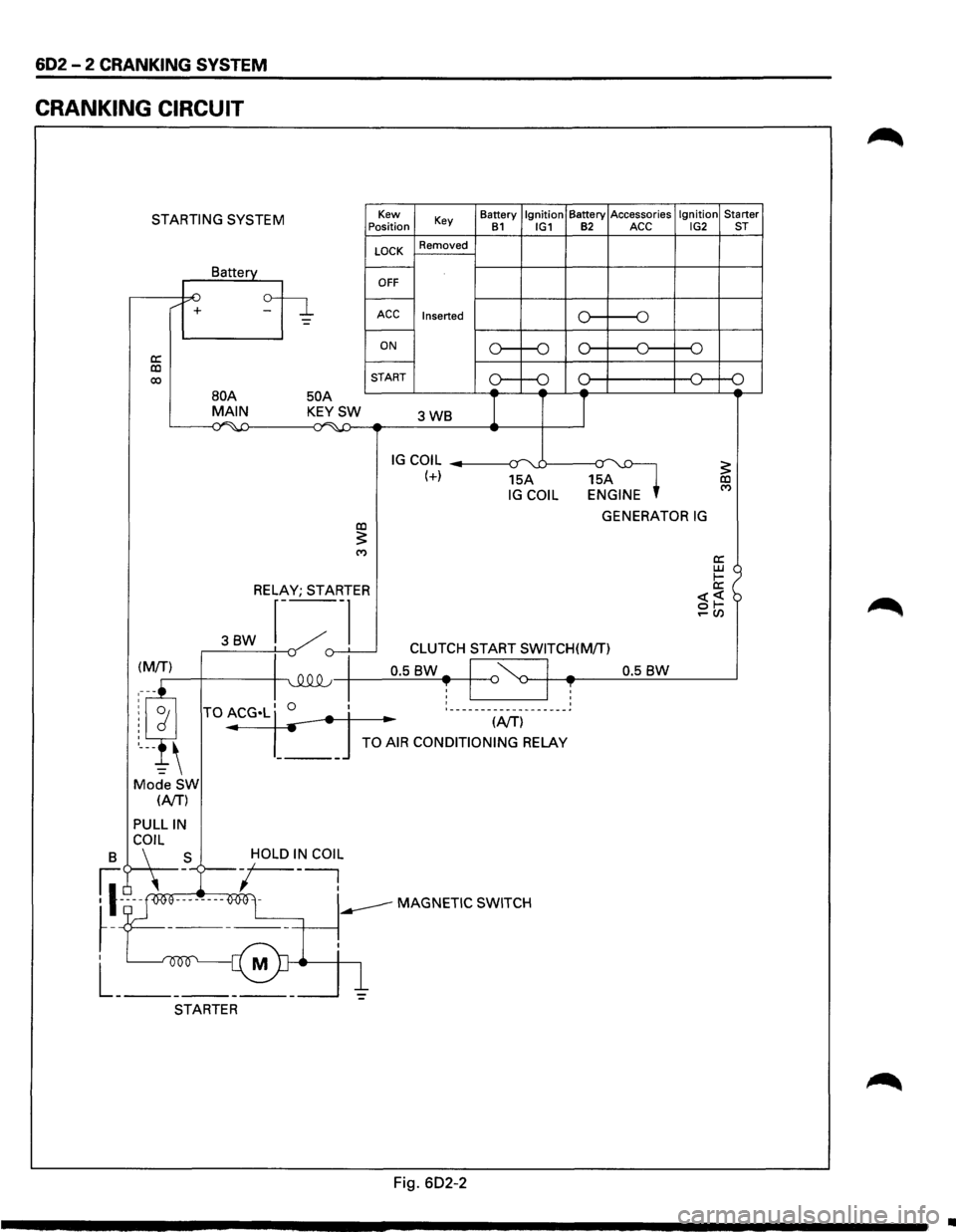
CRANKING CIRCUIT
The cranking system consists of a battery, starter,
starter switch, starter relay, etc. and these main com-
Pull in coil
Hold
in coil
Plunger
Shift lever
Pinion clutch
Internal
gear
Planetary gear
ponents are connected as shown in Fig. 602-1. For
details of the cranking circuit, see Fig. 602-2.
Anti theft controller or mode switch
Battery
(AfT} '-------------. ' '
To Generator "B" terminal
Fig. 602-1
STARTER
The cranking system employs a magnetic type reduc
tion starter in which the motor shaft is also used as a
pinion shaft. When the starter switch is turned on, the
contacts of magnetic switch are closed, and the arma
ture rotates. At the same time, the plunger is attracted,
and the pinion is pushed forward by the shift lever to
mesh with ring gear. Then, the ring gear runs to start
the engine. When the engine starts and the starter
switch is turned off, the plunger returns, the pinion is
disengaged from ring gear, and the armature stops
rotation. When the engine speed is higher than the
pinion, the pinion idles, so that the armature is not
driven.
Page 660 of 1928
602 - 2 CRANKING SYSTEM
CRANKING CIRCUIT
STARTING SYSTEM
a: co 00
/ +
Battery
50 A
Kew
Position
LOCK
OFF
Key
Removed
ACC Inserted
ON
START Battery
Ignition Battery
Accessories Ignition Starter B1 IG1 B2 ACC IG2 ST
o----o
o----o
oc l---+----+--<0---o
BOA MAIN KEYSW 3WB I I ~~ ...;~-4:) -
IG COIL --------1~-:r uJ----a~ (+) 15A 15A IG COIL ENGINE
GENERATOR IG co :5: ('f)
RELAY; STARTER
3BW r---~
._,()-.L___j -v CLUTCH START SWITCH(M/T)
0.5
BW-I '~ I -0.5 BW ~-+-4~--~~~------~ T I ~ I T : ___________________ ~
.. (NT)
TO AIR CONDITIONING RELAY
Mode SW (NT)
PULLIN
B C\~L _S -/OLD I~ COl~
fl-~ooe--------O<>Ol -----MAGNETIC SWITCH
~-T ------+-----~.
I M
L _______ _
STARTER
Fig. 602-2
•
Page 663 of 1928
CRANKING SYSTEM 602-5
MAGNETIC SWITCH DOES NOT OPERATE THOUGH STARTER SWITCH IS TURNED TO "START (ST)"
CHECK IF VOLTAGE IS PRESENT AT MAGNETIC
SWITCH TERMINAL "S" WHEN STARTER SWITCH
IS TURNED TO "START (ST)"
YES
I NO I
CHECK GROUND CABLE I CHECK IF INDICATOR LAMP ON METER COMES ON NORMALLY
I
I
YES I NO I YES I I I
NO
I REPAIR I CHECK CONTINUITY DISCONNECTION OR
STARTER SWITCH AND FAULTY CONNECTION
OR MAGNETIC
SWITCH BETWEEN BATTERY
TERMINAL "S" AND STARTER SWITCH
I PINION
MAGNETIC SWITCH
SLIDING
OR COIL IS I REPAIR I PART DOES DISCONNECTED NOT MOVE OR BURNED OUT CHECK STARTER FAULTY CONNECTION
I
RELAY OR STARTER SWITCH
I
REPAIR OR REPLACE STARTER I CHECK CLUTCH REPLACE STARTER
START SWITCH SWITCH
Page 664 of 1928
602-6 CRANKING SYSTEM
PINION MESHES WITH RING GEAR BUT ENGINE DOES NOT CRANK
CHECK
GROUND CABLE I
I
YES I NO I
I
REPAIR OR REPLACE I GROUND CABLE
I I I I
FAULTY CONNECTION BURNED-OUT DISCONNECTION DISCONNECTION SLIP OF OF BRUSH AND MAGNETIC OR DAMAGE OF OR DAMAGE OF PINION COMMUTATOR STARTER
SWITCH FIELD COIL ARMATURE COIL CLUTCH
I I I J
REPAIR OR REPLACE STARTER I
•
Page 698 of 1928
6E2-2 DRIVEABILITY AND EMISSIONS
DRIVEABILITV AND EMISSIONS GENERAL INFORMATION
CONTENTS
General Information
Driveability ....................... .
Emissions
........................ .
Maintenance
Schedule .............. .
Introduction ...................... .
Electronic Engine
Control .......... .
What This Section Contains ........ .
Blocking Drive Wheels
Visual/Physical
Underhood Inspection
6E2-3
6E2-3
6E2-3
6E2-3
6E2-3
6E2-3
6E2-3
6E2-3
Basic
Knowledge required . . . . . . . . . . . . 6E2-4
Basic Electric Circuits . . . . . . . . . . . . . .
6E2-4
Use
of Circuit Testing Tools . . . . . . . . . 6E2-4
Use
of Digital Volt-Ohm Meter (DVOM). 6E2-4
Diagnostic
Information . . . . . . . . . . . . . . . 6E2-4
"Check Engine" Malfunction Indicator
Lamp (MIL) . . . . . . . . . . . . . . . . . . . . 6E2-4
Intermittent "Check Engine"
Malfunction Indicator Lamp (MIL) . . 6E2-4
Reading Diagnostic
Trouble Codes . . . 6E2-5
Clearing
Trouble Codes . . . . . . . . . . . . 6E2-5
Diagnostic Test
Mode .............. 6E2-5
Engine Control
Module Learning
Ability . . . . . . . . . . . . . . . . . . . . . . . . 6E2-6
Field
Service Mode . . . . . . . . . . . . . . . . 6E2-6
Standard Nomenclature
for Certain
Electrical/Electronic
Components
and Systems . . . . . . . . . . . . . . . . . . . 6E2-6
Abbreviations and Glossary of Terms ..... 6E2-11
Driveability and Emissions
Section Summary ................... 6E2-12
Section .,. A"
Diagnostic Procedure Summary ...... 6E2-13
Data Link Connector
"SCAN Tools" ..... 6E2-14
Data
List (FO) ...................... 6E2-14
"SCAN Tool" Limitations and Use ...... 6E2-14
Intermittent Conditions ............ 6E2-14
"SCAN Tool" Positions ............... 6E2-14
Injector Pulse Width ............... 6E2-14
Closed Loop/Open Loop . . . . . . . . . . . .
6E2-14
Trouble Codes ................... 6E2-14
Throttle Position (TP) Sensor . . . . . . . . 6E2-14
Throttle Angle . . . . . . . . . . . . . . . . . . . 6E2-15 Heated
Oxygen
Sensor (H02S)
Vehicle Speed Sensor (VSS) ....... .
Programmable Read Only Memory ID .
Revolution
Per Minute (RPM) ...... .
Mile Per Hour (MPH) ............. .
Engine
Coolant Temperature (ECT) .. .
Intake Air Temperature (IAT)
Sensor
...................... .
Manifold Absolute Pressure (MAP) .. .
Barometric Pressure (BARO) ....... .
Exhaust Gas Recirculation
(EGR)
(ON/OFF) .................... .
Short Term (S.T.) Fuel Trim and
Long Term
(LT.) Fuel Trim ...... .
Long Term
(LT.) Fuel Trim ........ .
Idle Air Control (lAC) Counts ....... .
Desired Revolution
Per Minute ..... .
Air Conditioning (A/C) Request ..... .
Air Conditioning (A/C) Clutch ...... .
Power Steering Pressure (PSP)
Switch ...................... .
Battery Positive Voltage .......... .
Spark Advance .................. .
Start Up Engine Coolant .......... .
Engine
Speed (RPM) ............. .
Fuel Trim Enable ................ .
Air/Fuel Ratio .................. .
Induction Air Control ............. .
Section B -Driveability Symptoms ... .
Section C -Component Systems .... .
Engine
Control Module (ECM)
and
Sensors .................. .
Fuel Control System ............. .
Electric
Fuel Pump (in-tank) ....... .
Evaporative Emission
(EVAP)
Control System ................ .
Ignition Control (IC) .............. .
Exhaust Gas Recirculator
(EGR) .... .
Air Conditioning (A/C) Clutch Control .
Positive Crankcase Ventilation (PCV) .
Tools Needed
to Service the System .... .
General Specifications
............... .
Vacuum Hose Routing Diagram
........ .
6E2-15
6E2-15
6E2-15
6E2-15
6E2-15
6E2-15
6E2-15
6E2-15
6E2-15
6E2-15
6E2-15
6E2-16
6E2-16
6E2-16
6E2-16
6E2-16
6E2-16
6E2-16
6E2-16
6E2-16
6E2-16
6E2-16
6E2-16
6E2-16
6E2-16
6E2-16
6E2-17
6E2-17
6E2-17
6E2-17
6E2-17
6E2-17
6E2-17
6E2-17
6E2-18
6E2-21
6E2-22
~
... ...
•
Page 704 of 1928
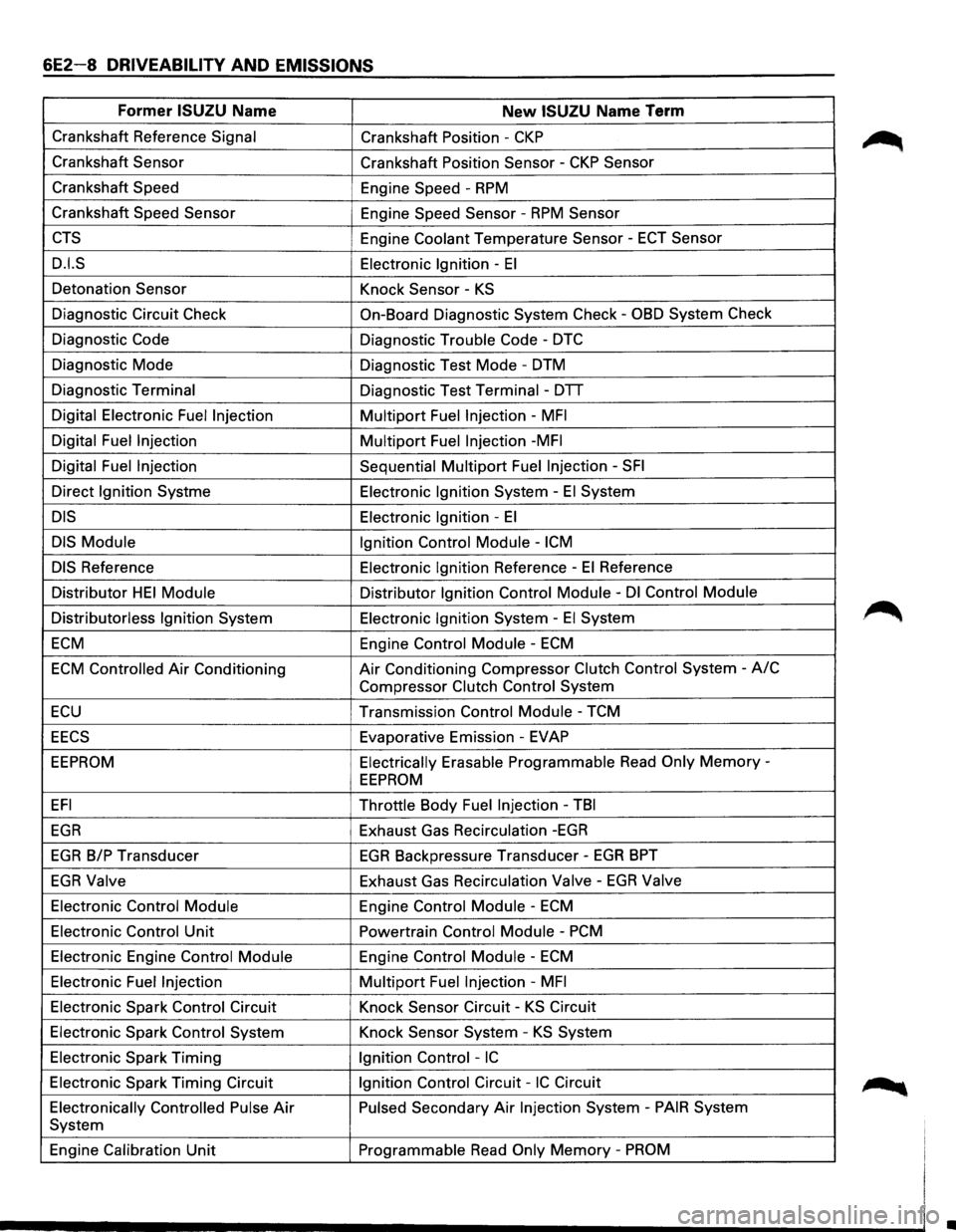
6E2-8 DRIVEABILITY AND EMISSIONS
Former ISUZU Name New ISUZU Name Term
Crankshaft Reference Signal Crankshaft Position -CKP
Crankshaft Sensor
Crankshaft Position Sensor -CKP Sensor
Crankshaft Speed
Engine Speed -
RPM
Crankshaft Speed Sensor
Engine Speed Sensor -RPM Sensor
CTS Engine Coolant Temperature Sensor -ECT Sensor
D.I.S Electronic Ignition -El
Detonation Sensor
Knock Sensor-KS
Diagnostic Circuit Check On-Board Diagnostic System Check -OBD System Check
Diagnostic Code Diagnostic Trouble Code -DTC
Diagnostic Mode
Diagnostic Test Mode-DTM
Diagnostic Terminal
Diagnostic Test Terminal -DTT
Digital Electronic
Fuel Injection Multipart Fuel Injection -MFI
Digital Fuel Injection Multipart Fuel Injection -MFI
Digital Fuel Injection Sequential Multipart Fuel Injection -SFI
Direct Ignition Systme Electronic Ignition System -El System
DIS Electronic Ignition -El
DIS Module
Ignition Control Module -ICM
DIS Reference Electronic Ignition Reference -El Reference
Distributor
HEI Module Distributor Ignition Control Module -Dl Control Module
Distributorless Ignition System Electronic Ignition System -
El System
ECM Engine Control Module -ECM
ECM Controlled Air Conditioning Air Conditioning Compressor Clutch Control System -A/C
Compressor Clutch Control System
ECU Transmission Control Module -TCM
EECS Evaporative Emission-EVAP
EEPROM Electrically Erasable Programmable Read Only Memory-
EEPROM
EFI Throttle Body Fuel Injection -TBI
EGR Exhaust Gas Recirculation -EGR
EGR B/P Transducer EGR Backpressure Transducer -EGR BPT
EGR Valve Exhaust Gas Recirculation Valve -EGR Valve
Electronic Control Module Engine Control Module -ECM
Electronic Control Unit Powertrain Control Module -PCM
Electronic Engine Control Module Engine Control Module -ECM
Electronic Fuel Injection Multipart Fuel Injection -MFI
Electronic Spark Control Circuit Knock Sensor Circuit -KS Circuit
Electronic Spark Control System Knock Sensor System -KS System
Electronic Spark Timing Ignition
Control -IC
Electronic Spark Timing Circuit Ignition Control Circuit -IC Circuit
Electronically Controlled Pulse
Air Pulsed Secondary Air Injection System -PAIR System
System
Engine
Calibration Unit Programmable Read Only Memory -PROM
•
Page 712 of 1928
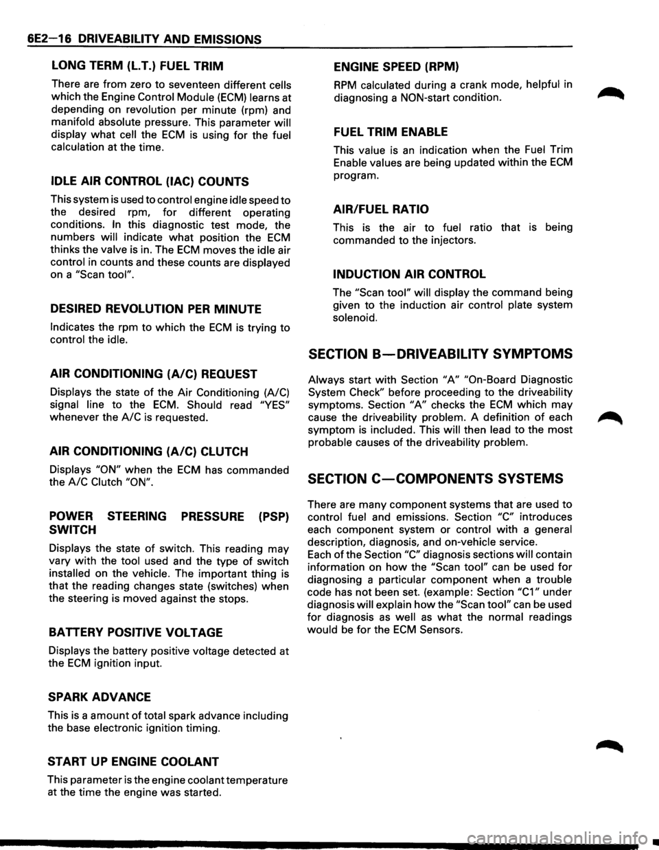
6E2-16 DRIVEABILITV AND EMISSIONS
LONG TERM (LT.) FUEL TRIM
There are from zero to seventeen different cells
which the Engine Control Module (ECM) learns at
depending on revolution per minute (rpm) and
manifold absolute pressure. This parameter
will
display what cell the ECM is using for the fuel
calculation at the time.
IDLE AIR CONTROL (lAC) COUNTS
This system is used to control engine idle speed to
the desired rpm, for different operating
conditions.
In this diagnostic test mode, the
numbers
will indicate what position the ECM
thinks the valve is in. The ECM moves the idle air
control in counts and these counts are displayed
on a
"Scan tool".
DESIRED REVOLUTION PER MINUTE
Indicates the rpm to which the ECM is trying to
control the idle.
AIR CONDITIONING (A/C) REQUEST
Displays the state of the Air Conditioning (A/C)
signal line to the ECM. Should read "YES"
whenever the A/C is requested.
AIR CONDITIONING {A/C) CLUTCH
Displays "ON" when the ECM has commanded
the
A/C Clutch "ON".
POWER STEERING PRESSURE (PSP)
SWITCH
Displays the state of switch. This reading may
vary
with the tool used and the type of switch
installed on the vehicle. The important thing is
that the reading changes state (switches) when
the steering is moved against the stops.
BA TTERV POSITIVE VOLTAGE
Displays the battery positive voltage detected at
the
ECM ignition input.
SPARK ADVANCE
This is a amount of total spark advance including
the base electronic ignition timing.
START UP ENGINE COOLANT
This parameter is the engine coolant temperature
at the
time the engine was started.
ENGINE SPEED (RPM)
RPM calculated during a crank mode, helpful in
diagnosing a NON-start condition.
FUEL TRIM ENABLE
This value is an indication when the Fuel Trim
Enable values are being updated within the ECM
program.
AIR/FUEL RATIO
This is the air to fuel ratio that is being
commanded to the injectors.
INDUCTION AIR CONTROL
The "Scan tool" will display the command being
given to the induction air control
plate system
solenoid.
SECTION B-DRIVEABILITY SYMPTOMS
Always start with Section "A" "On-Board Diagnostic
System Check" before proceeding to the driveability
symptoms.
Section "A" checks the ECM which may
cause the driveability problem. A definition
of each
symptom is included. This will then lead to the most
probable causes of the driveability problem.
SECTION C-COMPONENTS SYSTEMS
There are many component systems that are used to
control fuel and emissions. Section "C" introduces
each component system or control
with a general
description, diagnosis, and on-vehicle service.
Each
of the Section "C" diagnosis sections will contain
information on
how the "Scan tool" can be used for
diagnosing a particular component when a trouble
code has
not been set. (example: Section "C1" under
diagnosis
will explain how the "Scan tool" can be used
for diagnosis as well as what the normal readings
would be for the ECM Sensors.
•