cruise control ISUZU TROOPER 1995 Owner's Guide
[x] Cancel search | Manufacturer: ISUZU, Model Year: 1995, Model line: TROOPER, Model: ISUZU TROOPER 1995Pages: 1928
Page 1368 of 1928
8 -178 CHASSIS ELECTRICAL
ANTI-LOCK BRAKE SYSTEM (ABS)
GENERAL DESCRIPTION
The circuit consists of the starter switch, stoplight switch (vehicle w/o cruise control), brake switch (vehicle
with cruise control), hydraulic unit, electronic brake control module, wheel speed sensor, G sensor, ABS and
4WD indicator, 4WD switch and data link connector.
When the service brake is applied while in the running mode,
the EBCM (Electronic Brake Control Module)
judges
which wheel is about to lock by using the wheel rotation speed signals sent from the four ABS speed
sensors at the
front and rear wheels. And the brake fluid pressure applied to the four wheels is controlled by
a hydraulic unit to prevent the wheels from locking.
Based on the wheel rotation speed signals
input from the ABS sensor, the EBCM sends out signals to the
solenoid valve in the hydraulic unit
to increase, maintain or decrease the brake fluid pressure. The solenoid
valve uses this signal
to control the fluid pressure which is applied to the calipers of the disk brakes of the
front wheels. (The system also controls at the same time the fluid pressure applied to the rear wheels.)
• EBCM (Electronic brake control module)
The EBCM uses the signals sent from the speed sensor to control the operation of the hydraulic unit.
When any malfunction occurs in the ABS, the
EBCM activates the fail-safe fuction while turning on the
ABS warning light.
• Hydraulic unit
The hydraulic unit consists of the motor, plunger pump, solenoid valve, and fluid pressure control
valves. The exterior
of the unit has a relay box consisting of the motor relay and valve relay. Three
solenoid valves, the
two of which are provided at the front wheels and the one at the rear wheels, control
the fluid pressure
of these wheels.
• Speed sensor
The speed sensor consists of the sensor and the rotor. It sends the EBCM the AC voltage generated by
the rotation of the rotor as the vehicle speed signal. ~
• G-sensor
The G-sensor, installed inside the center console, sends out signals to the EBCM by detecting the
decelerating speed
of the vehicle.
• ABS warning light
The ABS warning light in the instrument panel, lights up when any malfunction occurs in the ABS. It also
lights up
with the starter key at the "ON" position, as a self-check.
Refer
to Section 5A4, "ANTI-LOCK BRAKE SYSTEM" for detail.
II
Page 1369 of 1928
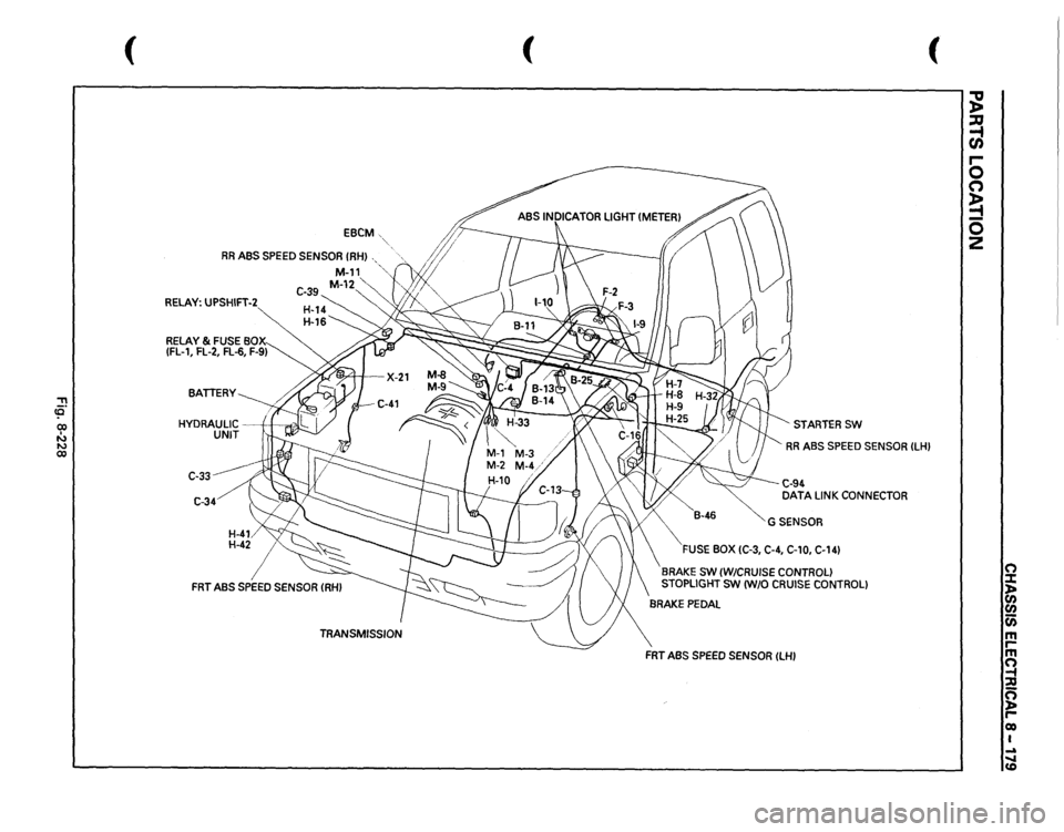
::!! (Q 00 I N N 00
(
EBCM
RR
ABS
SPEED
SENSOR
(RHI
RELAY:
UPSHIFT-2
C-33 C-34
(
(
STARTERSW RR
ABS
SPEED
SENSOR
ILHI
C-94 DATA
LINK
CONNECTOR
GSENSOR
FUSE
BOX
(C-3,
C-4,
C-10,
C-141
BRAKE
SW
(W/CRUISE
CONTROL)
STOPLIGHT
SW
IW/0
CRUISE
CONTROL)
FRT
ABS
SPEED
SENSOR
ILHI
~ :a -t CJ) r-0 (") ~ 0 z
(") :::t ln en (i) m rm ~ :;g n ~ r-eo I ..a ..... CD
Page 1375 of 1928
CHASSIS ELECTRICAL 8-185
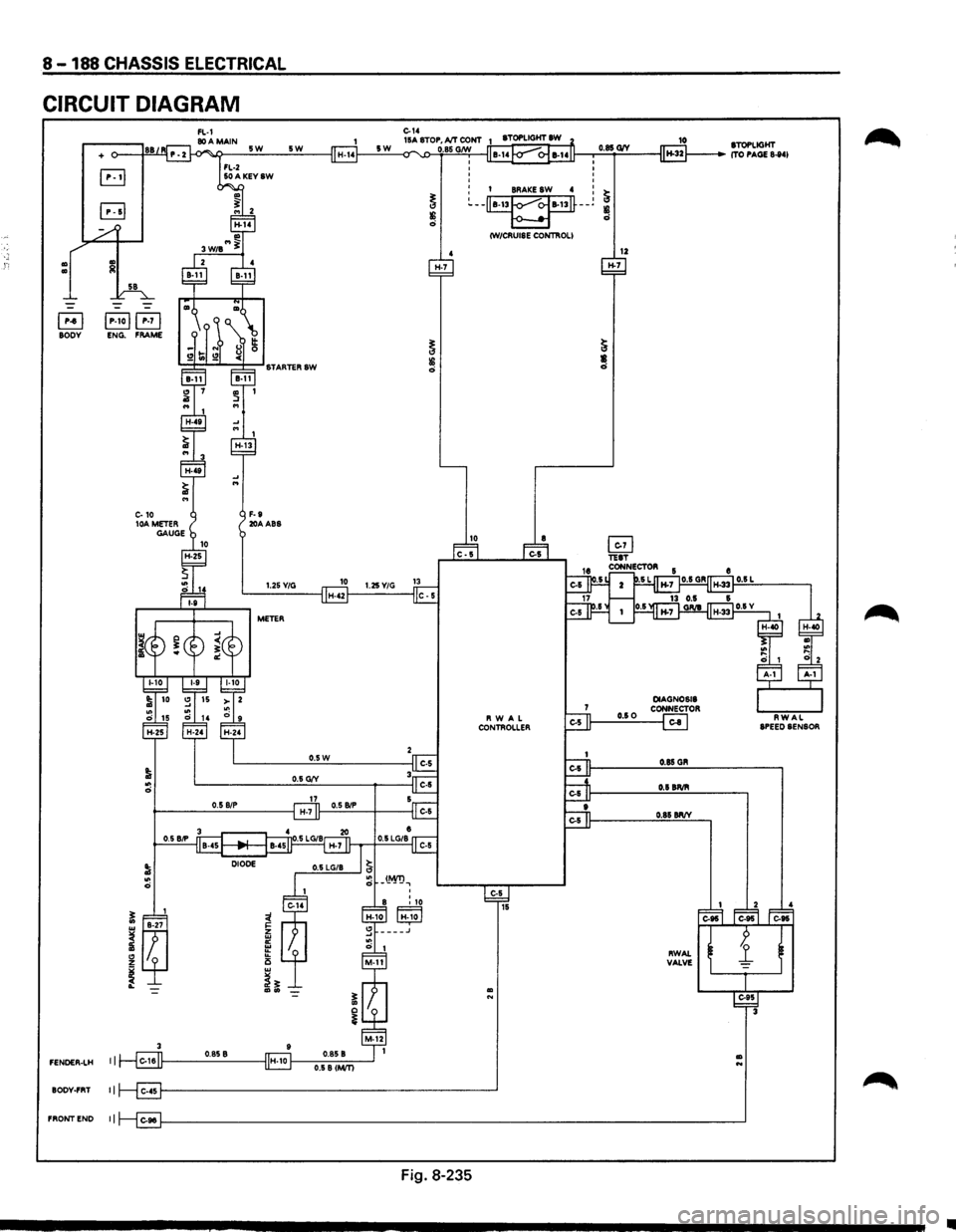
REAR WHEEL ANTI-LOCK BRAKE SYSTEM (RWAL)
GENERAL DESCRIPTION
The circuit consists of the starter switch, stoplight switch (vehicle w/o cruise control), brake switch (vehicle
w/cruise control). RWAL controller, RWAL speed sensor, RWAL valve, brake differential switch, 4WD switch,
parking brake
SW, indicator light (RWAL, 4WD, BRAKE), and test connector.
In this system, when the service brake is applied the RWAL controller judges the wheel rotation difference
signals which have been sent from the RWAL speed sensor at the rear axle differential. The anti-lock valves
control
the brake fluid pressure which is applied to the rear wheels to prevent the wheels from locking.
When starting the engine, the RWAL indicator in the instrument panel lights up at the same time as the brake
indicator
to inform the driver that the system is operating normally. (The light goes off after two seconds.)
Refer
to Section 5A3, "RWAL (REAR WHEEL ANTI-LOCK BRAKE SYSTEM)" for detail.
Page 1377 of 1928
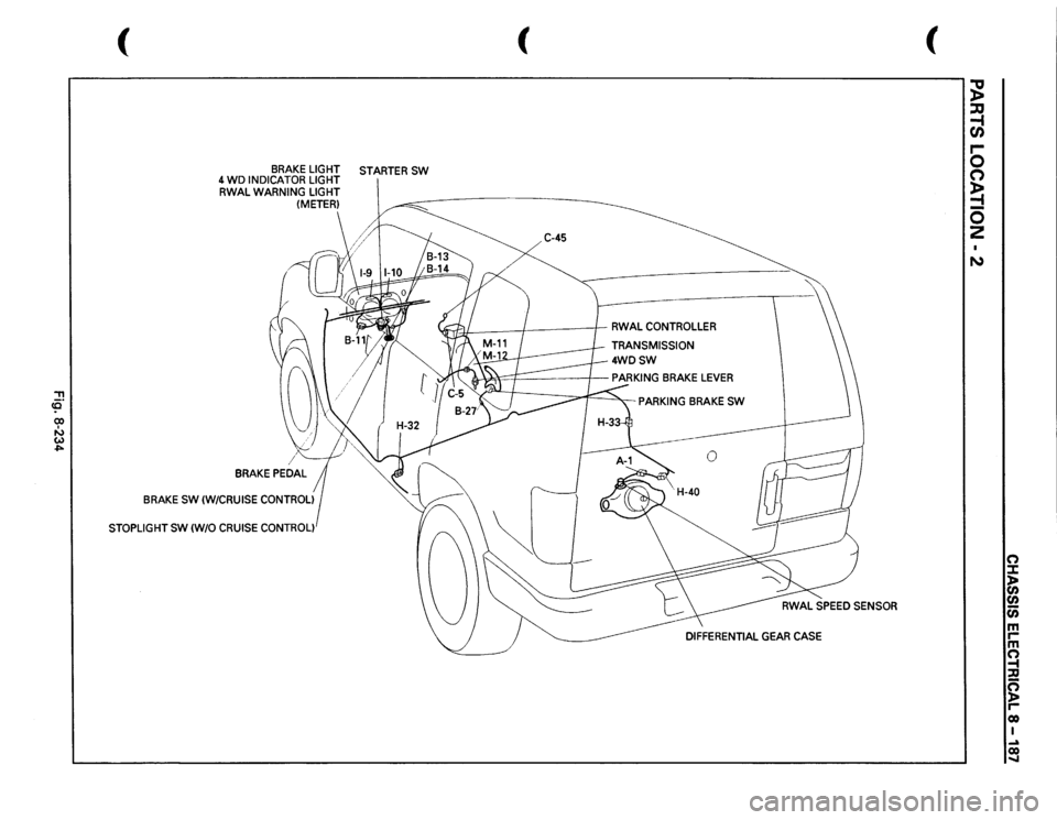
::!! (Q 00 I ....., w ..,..
(
BRAKE
LIGHT
STARTER
SW
4 WD
INDICATOR
LIGHT
RWAL
WARNING
LIGHT (METER)
BRAKE
SW
(W/CRUISE
CONTROL)
STOPLIGHT
SW
(W/0
CRUISE
CONTROL)
(
C-45
JfJI:
/
I
RWAL
CONTROLLER
TRANSMISSION
4WDSW
PARKING
BRAKE
SW
(
;g ::JJ -1 en .... 0 0 ~ -0 2 N
n :I: l> en en c;; m rm n -t :a g reo I ~ co .....
Page 1378 of 1928
8-188 CHASSIS ELECTRICAL
CIRCUIT DIAGRAM
Ill Ill
+
B jP-toj~ BODY ENG. FRAME
3
FENOER-LH I I
BODY-FRT II
FRONTEND II
5W
F-9 20AABS
5W
1.25Y/G
METER
H-7
0
0 0
0
0.85 G1V
o I BRAKE SW 4 : ~ ~--~--~
~ ~ CW/CRUISE CONTROLI
12 H-7
Fig. 8-235
10 STOPLIGHT ITO PAGE 8-841
•
Page 1390 of 1928
8 -200 CHASSIS ELECTRIC'Al
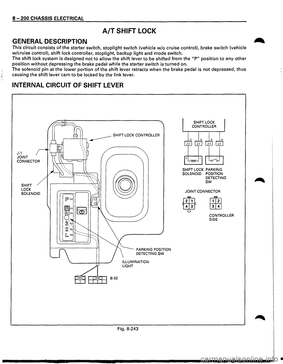
A/T SHIFT LOCK
GENERAL DESCRIPTION
This circuit consists of the starter switch, stoplight switch (vehicle w/o cruise control), brake switch (vehicle
w/cruise control),
shift lock controller, stoplight, backup light and mode switch.
The shift lock system is designed not
to allow the shift lever to be shifted from the "P" position to any other
position
without depressing the brake pedal while the starter switch is turned on.
The solenoid pin at the
lower portion of the shift lever retracts when the brake pedal is not depressed, thus
causing the shift lever cam
to be locked by the link lever.
INTERNAL CIRCUIT OF SHIFT LEVER
J-1 JOINT CONNECTOR
SHIFT
LOCK
SOLENOID
B-32
PARKING POSITION
DETECTING SW
ILLUMINATION LIGHT
Fig. 8-243
SHIFT LOCK PARKING
SOLENOID POSITION
DETECTING
sw
JOINT CONNECTOR
CONTROLLER
SIDE
•
Page 1391 of 1928

"T1 ce· 00 I N ~ ~
(
BRAKE
SW
(W/CRUISE
CONTROL)
STOPLIGHT
SW
(W/0
CRUISE CONTROL)
SHIFT
LEVER
" ""'
SHIFT
LOCK
CONTROLLER
""''
RELAY
& FUSE
BOX
(FL-1,
FL-2)
(
STARTERSW
BRAKE
PEDAL
STOP
LIGHT
(LH)
\R-7 "-TRAILER
HARNESS
CONNECTOR
(H-44)
(
;g ~ r-0 0 ~ 5 z
0 :J: ~ en u; m rm ~ :a g reo I N 0 ....
Page 1480 of 1928
•
, ce· CX) I w w .....
..
~ m
0
z
0 0 <
m
n
"'
-1
:D
"'
:z:
= ~~ :;; )
O.SIItll 2B
O.&B
ID
-,~
r
-•3
'
.. '
'
' ' IGNITION
CONTROL
MODULECTO
PAGE
S.S1,
531
ECMCASI
(TO PAGE
11-51,
531
TCMihl (TO PAGE
8-1t41
TCMIA111 (TO PAGE
11-1141
~[~} m[i] ~ .:. II
. 0 j[~}l
I'lL,
II"
:----~
.. :~.:,._
:
fill
:~
~~~~ I -··
.!., -
SPEEOOMETER TACHOMETER VOLTMETER ENGINE
COOLANT
TEMPERATURE
GAUGE
OIL PRESSUSRE
GAUGE
FUEL
GAUGE MALFUNCT10N
INDICATOR
lCHECKENGWEI
POWEll -TER
)
O.SL
ECMIDIII
ITO PAGE
11-51,
531
CRUISE
CONTROL UNITI131 ITO PAGE
11-1741
O.SLJY ;;
~ ~ '!' ;;: ~ ~ n ~ ~ )
n -:JJ n c =i c -)> G) :JJ )> 3:
co I N CD 0 (") :.t: > Cl) Cl) Cl) m ,.... m Q , n )> ,....
Page 1577 of 1928
RADIO 9A-1
ACCESSORIES
Radio .................................................. .
Parts Location ..............................•...........
Circuit Diagram ......•.................................
Antenna ....•......................................•........
Auto Antenna ......................................... .
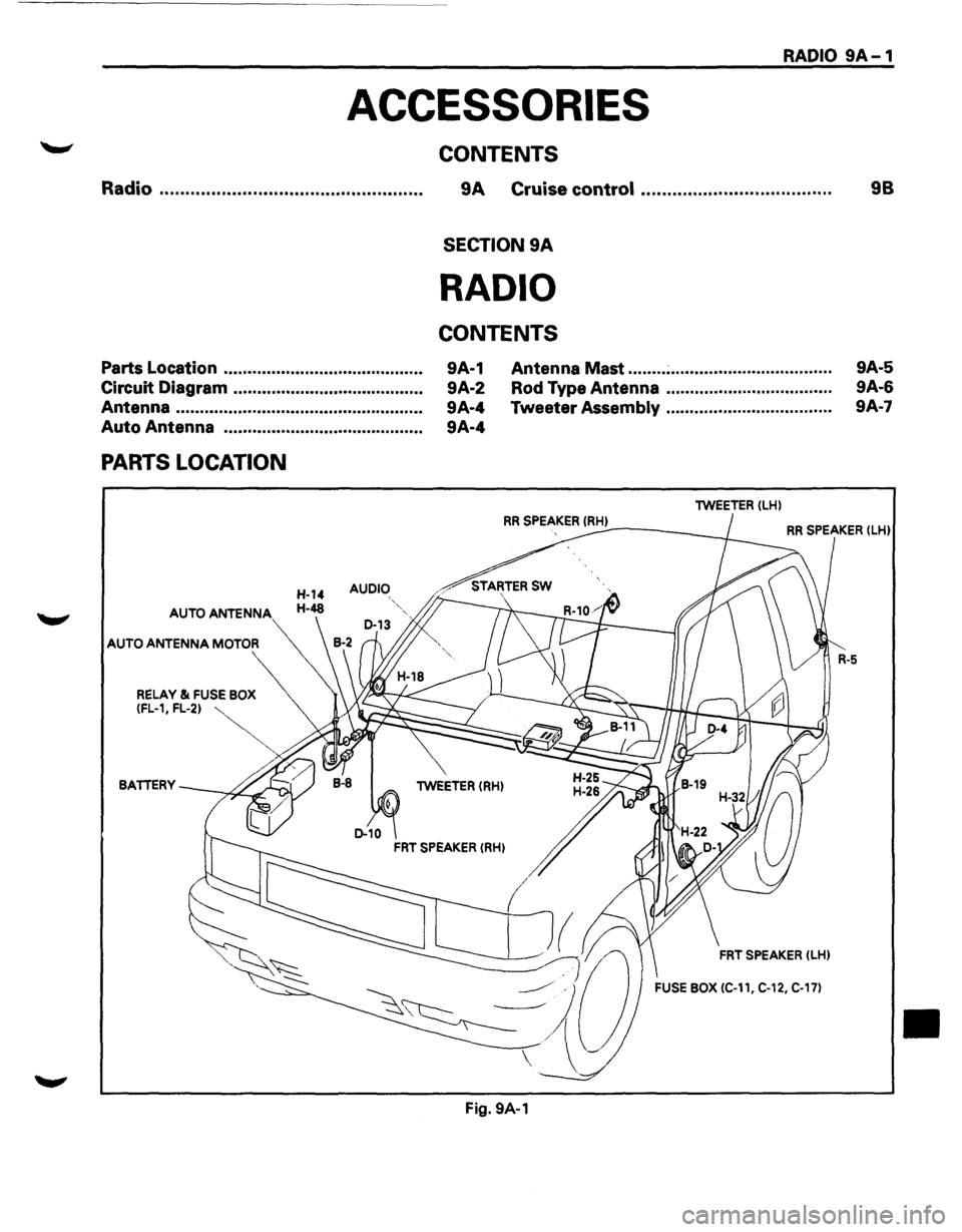
PARTS LOCATION
AUDIO
AUTO ANTENNA
AUTO ANTENNA MOTOR
CONTENTS
9A Cruise control ................................... ..
SECTION 9A
RADIO
CONTENTS
9A-1
9A-2
9A-4
9A-4 Antenna
Mast ........ ~ ................................. .
Rod Type Antenna .................................. .
Tweeter
Assembly .................................. .
lWEETER (LH)
98
9A-5
9A-6
9A·7
RR SPEAKER !RH) ----~ RR SPEAKER (lHl
BATTERY lWEETER (RH)
FRT SPEAKER (LHl
FUSE BOX (C-11, C-12, C-17)
Fig. 9A-1
•
Page 1585 of 1928
---------------~-~---
CRUISE CONTROL 9B-1
SECTION 98
CRUISE CONTROL
CONTENTS
General description ................................ .
Parts location .......................................... .
Circuit diagram ....................................... .
Diagnosis ................................................. .
On-vehicle service ................................. ..
Brake switch adjustment ................ ..
Clutch switch adjustment ................ .
Actuator
cable adjustment .............. .
Starter switch ................................... .
Cruise control main switch .............. .
GENERAL DESCRIPTION
98-1
9B-3
98-4
9B-7
98-28
9B-28
9B-28
9B-28
9B-28
9B-30 Cruise
control
switch
(combination switch) ........................ 98-31
Cruise control unit .......................... ... 9B-32
Pump
& actuator .................. .............. 9B-34
Brake switch ....................................... 9B-36
Clutch switch .............................. ....... 9B-36
Mode switch .. .. .. .. .. .. .. .. .. .. .. .. .. .. .. .. .. .. .. . 9B-37
Vehicle speed sensor
(incorporated in speedometer) ......... 9B-38
Diode
.. .. .. .. .. .. . .. .. .. .. .. . .. .. .. .. .. .. .. .. .. .. . .. .. .. 9B-38
Cruise control main relay .................. 9B-39
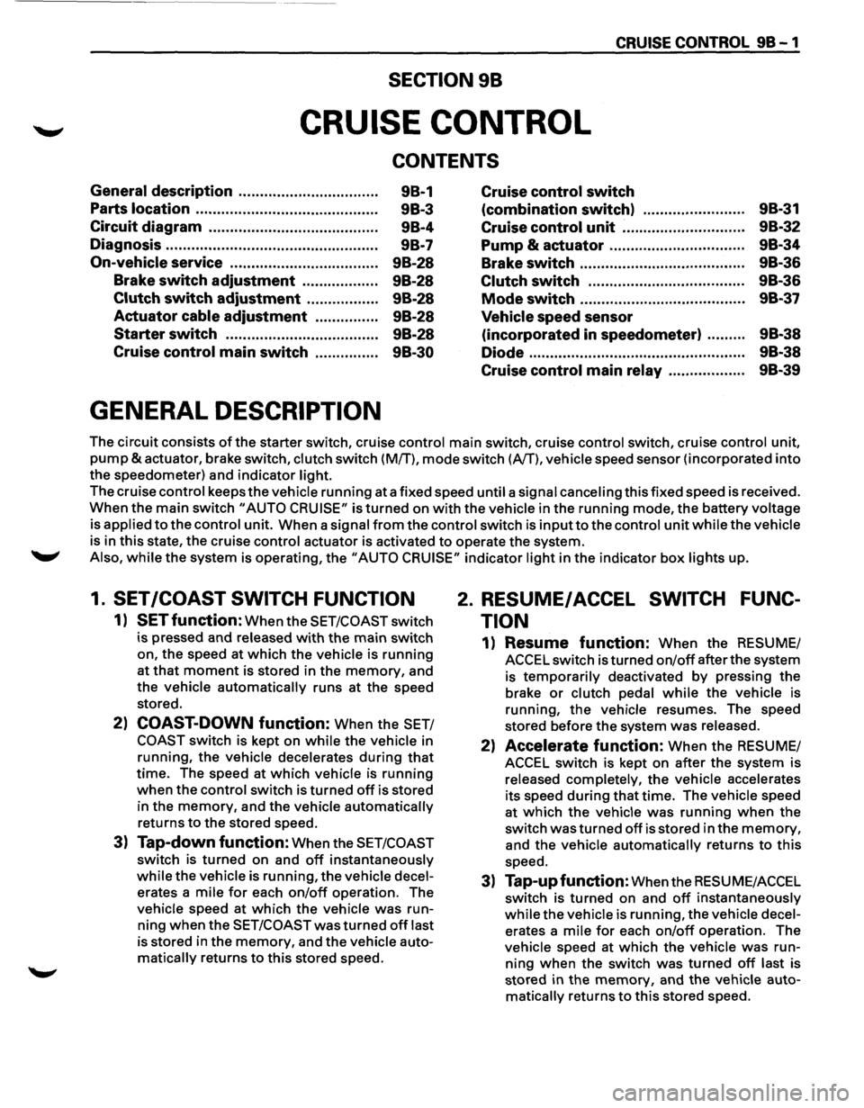
The circuit consists of the starter switch, cruise control main switch, cruise control switch, cruise control unit,
pump &actuator, brake switch, clutch switch (M/T), mode switch (A/T), vehicle speed sensor (incorporated into
the speedometer) and indicator light.
The cruise control keeps
the vehicle running at a fixed speed until a signal canceling this fixed speed is received.
When the main switch "AUTO CRUISE" is turned on with the vehicle in the running mode, the battery voltage
is applied
to the control unit. When a signal from the control switch is input to the control unit while the vehicle
is in this state, the cruise control actuator is activated to operate the system .
.._, Also, while the system is operating, the "AUTO CRUISE" indicator light in the indicator box lights up.
1. SET /COAST SWITCH FUNCTION
1) SET function: When the SET/COAST switch
is pressed and released
with the main switch
on, the speed at
which the vehicle is running
at that moment is stored in the memory, and
the vehicle
automatically runs at the speed
stored.
2) COAST-DOWN function: When the SET/
COAST switch is kept on while the vehicle in
running, the vehicle decelerates
during that
time. The speed at which vehicle is running
when the control switch is turned off is stored
in the
memory, and the vehicle automatically
returns
to the stored speed.
3) Tap-down function: When the SET/COAST
switch is turned on and off instantaneously
while the vehicle is running, the vehicle decel
erates a mile for each on/off operation. The
vehicle speed at
which the vehicle was run
ning when the SET/COAST was turned off last
is stored in the
memory, and the vehicle auto
matically returns to this stored speed.
2. RESUME/ ACCEL SWITCH FUNC
TION
1) Resume function: When the RESUME/
ACCEL switch is turned
on/off after the system
is
temporarily deactivated by pressing the
brake or clutch pedal while the vehicle is
running,
the vehicle resumes. The speed
stored before the system
was released.
2) Accelerate function: When the RESUME/
ACCEL switch is kept on after the system is
released completely, the vehicle accelerates
its speed
during that time. The vehicle speed
at
which the vehicle was running when the
switch
was turned off is stored in the memory,
and the vehicle automatically returns to this
speed.
3) Tap-up function: When the RESU ME/ACCEL
switch is
turned on and off instantaneously
while the vehicle is running, the vehicle decel
erates a mile for each on/off operation. The
vehicle speed at
which the vehicle was run
ning when the switch was turned off last is
stored in the
memory, and the vehicle auto
matically returns to this stored speed.