cruise control ISUZU TROOPER 1995 Service Manual
[x] Cancel search | Manufacturer: ISUZU, Model Year: 1995, Model line: TROOPER, Model: ISUZU TROOPER 1995Pages: 1928
Page 1586 of 1928
98-2 CRUISE CONTROL
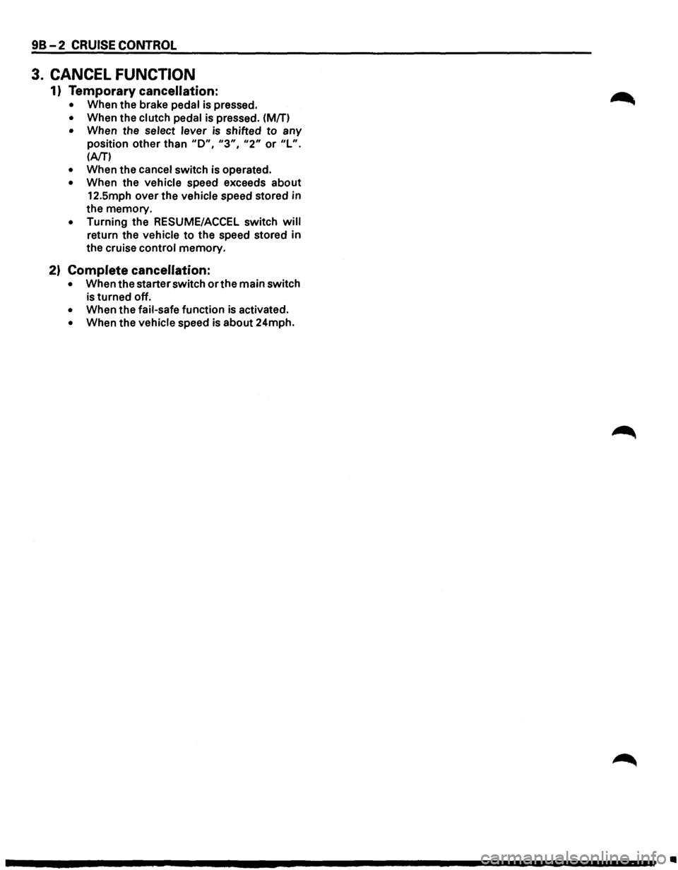
3. CANCEL FUNCTION
1) Temporary cancellation:
• When the brake pedal is pressed.
• When the clutch pedal is pressed. (Mfn
• When the select lever is shifted to any
position other than
"D", "3", "2" or "L".
(AfT')
• When the cancel switch is operated.
• When the vehicle speed exceeds about
12.5mph over the vehicle speed stored in
the memory.
• Turning the RESUME/ACCEL switch will
return the vehicle to the speed stored in
the cruise control memory.
2) Complete cancellation:
• When the starter switch or the main switch
is turned off.
• When the fail-safe function is activated.
• When the vehicle speed is about 24mph.
Ill
Page 1587 of 1928
, cCi" <0 CD I ....
( (
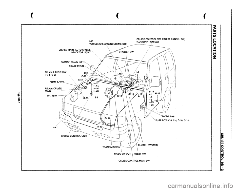
1-10
CRUISE CONTROL SW,
CRUISE
CANSEL SW,
!COMBINATION
SWl
VEHICLE
SPEED
SENSOR
!METER}
i
CRUISE MAIN, AUTO CRUISE
INDICATOR LIGHT
CLUTCH
PEDAL
IM[T)
~
. //
BRAKE PEDAL
~~
RELAY &
FUSE BOX
B-2
vi"""
(FL-1
FL-2}
C-3g\j;~
PUMP&VSV
RELAY:
CRUISE
MAIN BATTERY--
/
H-41
··,.
,:-,
\
·.,"-
~DIODE
8-45
'"-FUSE
BOX IC-3, C-4, C-10,
C-14)
CRUISE
CONTROL
MAIN
SW
(
~ ~ 0 n ~ 0 z
n ::D c c;; m n 0 ~ 0 r-fD OJ I w
Page 1588 of 1928
![ISUZU TROOPER 1995 Service Manual .,
~[~}
0
U)
..
m
.,
0
z
()
-
0
"
~
m
::g
"
c
I
+
I
;,
iii
~[]"
00
0
:I:
~
,.
z
" 0
!!
c:
(")
a
1@}1
..
=i
:u
"
~
c
0.5LfY
""
c
u;
-
m
-n
~~
)](/img/61/57183/w960_57183-1587.png "ISUZU TROOPER 1995 Service Manual .,
~[~}
0
U)
..
m
.,
0
z
()
-
0
\"
~
m
::g
\"
c
I
+
I
;,
iii
~[]\"
00
0
:I:
~
,.
z
\" 0
!!
c:
(\")
a
1@}1
..
=i
:u
\"
~
c
0.5LfY
\"\"
c
u;
-
m
-n
~~
)")
.,
~[~}
0
U)
..
m
.,
0
z
(')
-
0
"'
~
m
::g
"'
c
I
+
I
;,
iii
~[]"
00
0
:I:
~
,.
z
"' 0
!'!
c:
(")
a
1@}1
..
=i
:u
"'
~
c
0.5LfY
""
c
u;
-
m
-n
~~
)>
(")
~.:.
Q
0
0
'!::
'!::
CRUISE
CONTROl
MAIN
fNi
l~
!:
::g
2
z
"'
)>
-1
RELAY;TAll.lC)
1 e
3:
:u
lTO PAGE
8-78)
~
0 .-
.. ~
-~
.. ~
L___JI.,-L__Q
;~
l.,-11
I
lzl
1.!.1
1.!..1
I
0 .. ..
..
..
n
~
"'
"
s;
..
O.SGR/1.
TCMlB4l
....
..
= 0
m
m
•
lTO PAGE
8-195)
"'
g
..
..
z
~
~
:i1
0.51/W
~
~
li
::!!
I
~'==I
I ;
-
(Q
~
(0
;:
a:J
h:l
I
28
0.58
I
..
N
~
6-r
r ;:.:.
0.581\'11
~:::::::~
..
~
~ ..
J:w
!;.
m
_,
...
c
~
~ ~ i5
a.
~
;z
1i
(')
"
§
-·
I
O.SW/1.
J
I I
r-n
......
~
r=TI
I -
II-
I
...........
I
0 ilo .. l!! .,
·-
li
li
~
1.25
B
0.58
I%Tl
-
0.58
rr::l
I
;---..
I C11
.U...fl%1
0.5 11M!
I
I
I~
O.SSGIW
O.SIVY
o.as
RIB
0.5 GIVG
----------------------------------------------------------------------r-\
----,
CANCElfNi
Q.UTCH
fNi
1
.. ~
._____.
LL-J..
OSIVY
J~H~L
j~
------------------------------------------------------------------------\
--------------------------J
) )
)
•
Page 1589 of 1928
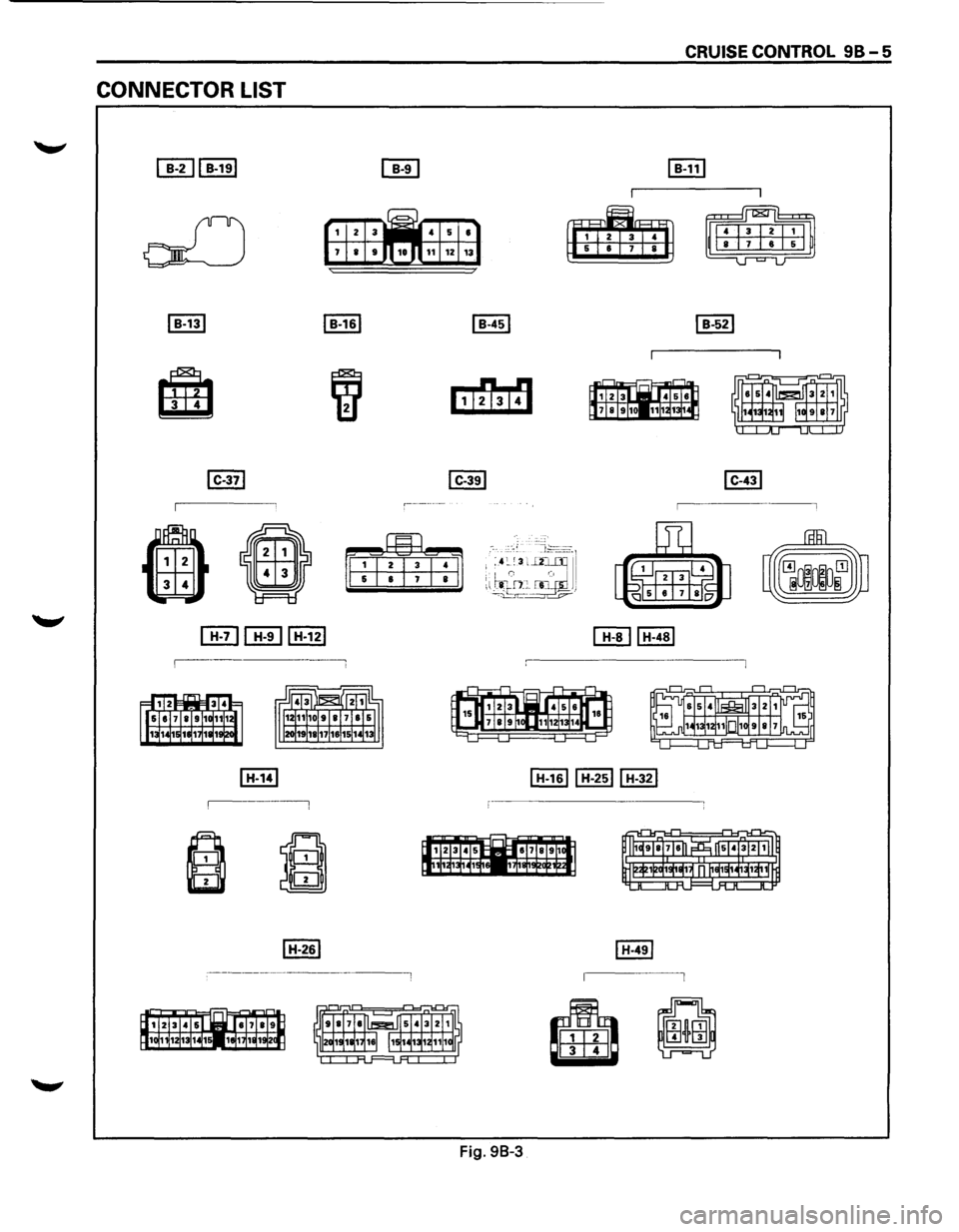
CONNECTOR LIST
4 5 •
11 1Z 13
Fig. 98-3
~
~
CRUISE CONTROL 98-5
Page 1590 of 1928
![ISUZU TROOPER 1995 Service Manual 98-6 CRUISE CONTROL
[till [ill [ill CITHEHEJ I P-10 I I X-201
r--~ ------
• II
~ I(g) Ei±8 4 -6
Fig.
98-4
..](/img/61/57183/w960_57183-1589.png "ISUZU TROOPER 1995 Service Manual 98-6 CRUISE CONTROL
[till [ill [ill CITHEHEJ I P-10 I I X-201
r--~ ------
• II
~ I(g) Ei±8 4 -6
Fig.
98-4
..")
98-6 CRUISE CONTROL
[till [ill [ill CITHEHEJ I P-10 I I X-201
r--~ ------
• II
~ I(g) Ei±8 4 -6
Fig.
98-4
..
Page 1591 of 1928
CRUISE CONTROL 98-7
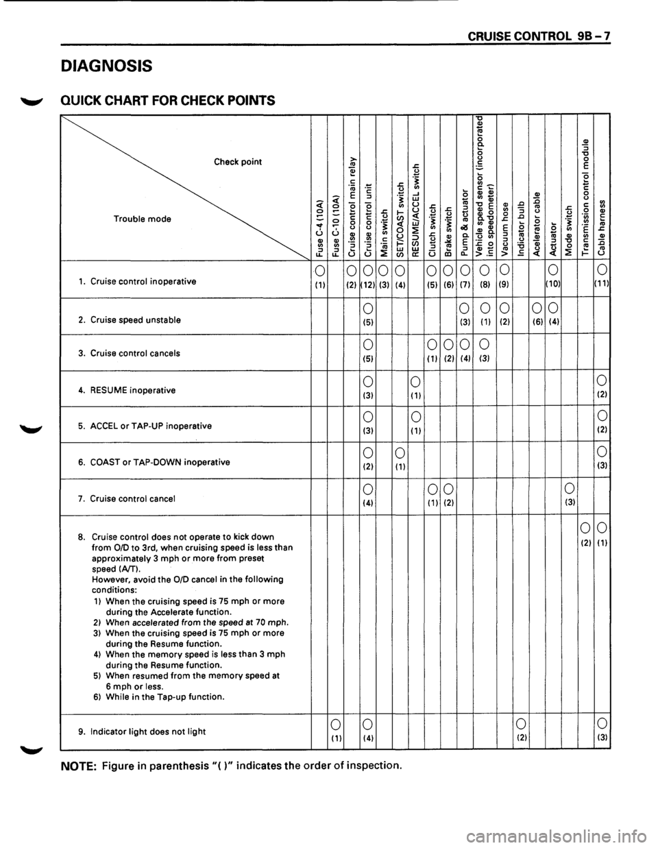
DIAGNOSIS
~ QUICK CHART FOR CHECK POINTS
"0 !!:! 0 0
CD 0 <( ::I ;: w ... Cl) Qi :0 0 <( Cl) 0 0 g Cl) u .r: .r: CD 0. 0 Cl) ::I
CD CD .!!! .!!! c: i==" 0 ""'" E :c 0 ::I 0 Qi :::1 "0 c: :0 en ... 0 '6 Cl) Cl) ::I ::I ·;a ::I
:::1 ... u w w .... ::I CD .,. ·= > .s <( ~ 1-u
0
0 0
0
0 0
0 0
0 0
0 0 1. Cruise control inoperative (
1) (2) (12) (3)
(4) (51 (6) (7) (8) (9) (10) (11)
0 0
0
0 0 0 2. Cruise
speed unstable (5) (3) ( 1) (2) (6) (4)
3. Cruise control cancels 0 0 0
0 0
(51 (
1) (2) (4) (3)
0 0 0 4. RESUME
inoperative (3) ( 1) (2)
0
0 0 5. ACCEL or TAP-UP
inoperative (3) ( 1) (2)
0
0 0 6. COAST or TAP-DOWN
inoperative (2) ( 1) (3)
0 0 0 0 7. Cruise control
cancel (4) ( 1) (2) (3)
0
0 8. Cruise control does not operate to kick down (2) (
1) from 0/D to 3rd, when cruising speed is less than approximately 3 mph or more from preset
speed (A/T). However, avoid the 0/D cancel in the following conditions:
1) When the cruising speed is 75 mph or more
during the
Accelerate function. 21 When accelerated from the speed at 70 mph. 3) When the cruising speed is 75 mph or more
during the Resume function.
4) When the memory speed is less than 3 mph
during the Resume function.
51 When resumed from the memory speed at
6 mph or less. 61 While in the Tap-up function.
9. Indicator light does not light 0 0 0
0 (
1) (4) (2) (3)
NOTE: Figure in parenthesis"()" indicates the order of inspection.
Page 1592 of 1928
98-8 CRUISE CONTROL
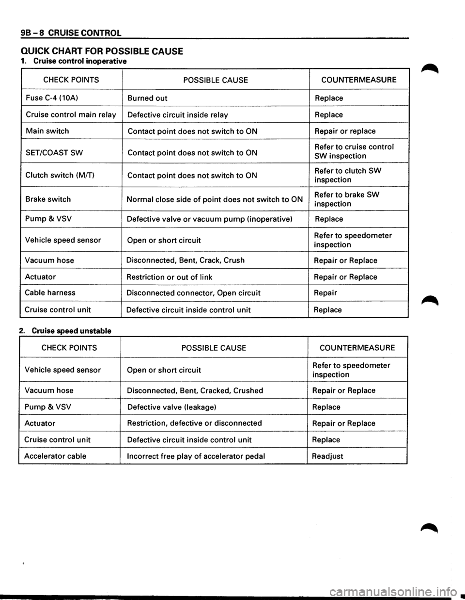
QUICK CHART FOR POSSIBLE CAUSE
1. Cruise control inoperative
CHECK POINTS POSSIBLE CAUSE
Fuse C-4 (10A) Burned out
Cruise control main relay Defective circuit inside relay
Main switch
Contact point does not switch to ON
SET/COAST SW Contact point does not switch to ON
Clutch switch (M/T)
Contact point does not switch to ON
Brake switch Normal close side of point does not switch to ON
Pump & VSV Defective valve or vacuum pump (inoperative)
Vehicle speed sensor Open or short circuit
Vacuum hose Disconnected, Bent, Crack, Crush
Actuator Restriction
or out of link
Cable
harness Disconnected connector, Open circuit
Cruise
control unit Defective circuit inside control unit
2. Cruise speed unstable
CHECK POINTS POSSIBLE CAUSE
Vehicle
speed sensor Open or short circuit
Vacuum hose
Disconnected, Bent, Cracked, Crushed
Pump & VSV Defective valve (leakage)
Actuator Restriction,
defective or disconnected
Cruise
control unit Defective circuit inside control unit
Accelerator cable
Incorrect free play of accelerator pedal COUNTERMEASURE
Replace
Replace
Repair or replace
Refer to cruise control
SW
inspection
Refer
to clutch SW
inspection
Refer
to brake SW
inspection
Replace
Refer to speedometer
inspection
Repair
or Replace
Repair or Replace
Repair
Replace
COUNTERMEASURE
Refer to speedometer
inspection
Repair
or Replace
Replace
Repair or Replace
Replace
Readjust
•
Page 1593 of 1928
-------------------
CRUISE CONTROL 98-9
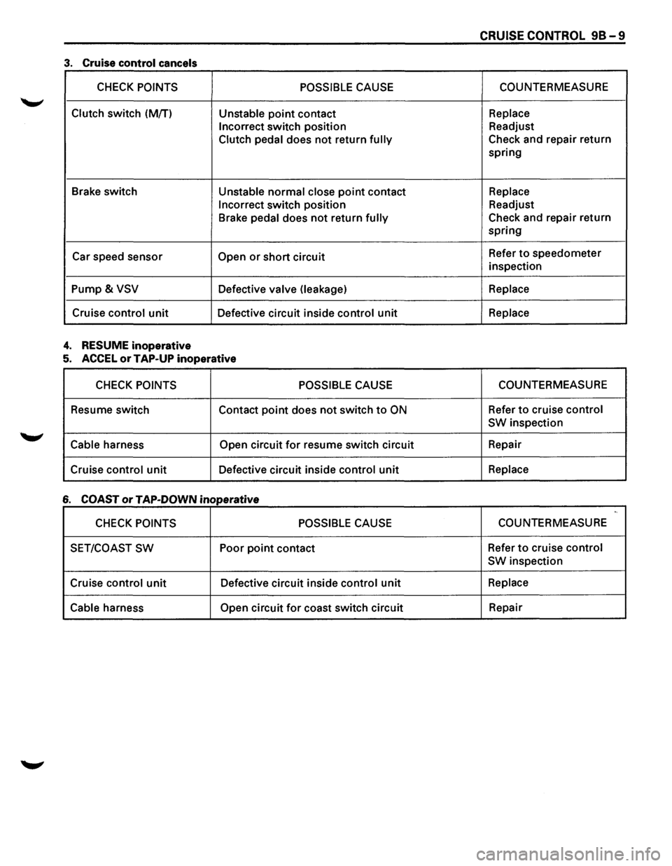
3. Cruise control cancels
CHECK POINTS POSSIBLE CAUSE COUNTERMEASURE
Clutch switch
(M/T) Unstable point contact Replace
Incorrect
switch position Readjust
Clutch
pedal does not return fully Check and repair return
spring
Brake switch
Unstable normal close point contact Replace
Incorrect
switch position Readjust
Brake
pedal does not return fully Check and repair return
spring
Car speed sensor
Open or short circuit Refer to speedometer
inspection
Pump& VSV Defective valve (leakage) Replace
Cruise control unit Defective circuit inside control unit Replace
4. RESUME inoperative
5. ACCEL or TAP-UP inoperative
CHECK POINTS POSSIBLE CAUSE COUNTERMEASURE
Resume switch
Contact
point does not switch to ON Refer to cruise control
SW
inspection
Cable harness Open circuit for resume switch circuit Repair
Cruise
control unit Defective circuit inside control unit Replace
6 COAST or TAP-DOWN inoperative ,,
CHECK POINTS POSSIBLE CAUSE COUNTERMEASURE
SET/COAST
SW Poor point contact Refer to cruise control
SW
inspection
Cruise
control unit Defective circuit inside control unit Replace
Cable
harness Open circuit for coast switch circuit Repair
Page 1594 of 1928
98-10 CRUISE CONTROL
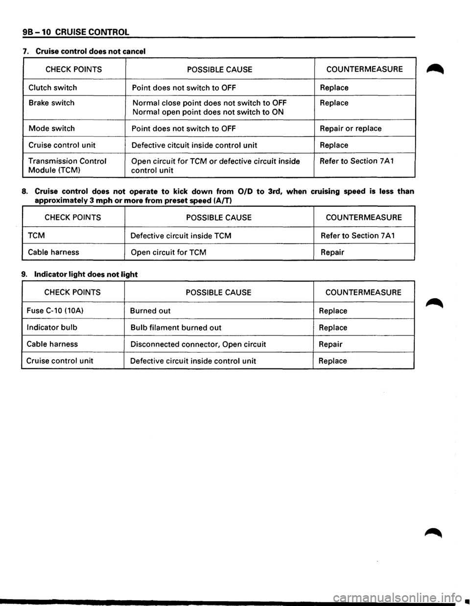
7. Cruise control does not cancel
CHECK POINTS POSSIBLE CAUSE COUNTERMEASURE
Clutch switch Point does not switch to OFF Replace
Brake switch
Normal close point does not switch to OFF Replace
Normal open point does not switch to ON
Mode switch Point does not switch to OFF Repair or replace
Cruise control unit
Defective citcuit inside control unit Replace
Transmission Control Open circuit for TCM or defective circuit inside Refer to Section
7 A 1
Module (TCM) control unit
8. Cruise control does not operate to kick down from 0/D to 3rd, when cruising speed is less than
approximately 3 mph or more from preset speed (A/T)
CHECK POINTS POSSIBLE CAUSE COUNTERMEASURE
TCM Defective circuit inside TCM Refer
to Section 7 A 1
Cable harness Open circuit for TCM
Repair
9. Indicator light does not light
CHECK POINTS POSSIBLE CAUSE COUNTERMEASURE
Fuse
C-10 (10A) Burned out Replace
Indicator
bulb Bulb filament burned out Replace
Cable
harness Disconnected connector, Open circuit Repair
Cruise
control unit Defective circuit inside control unit Replace
..
Page 1595 of 1928
CRUISE CONTROL 98-11
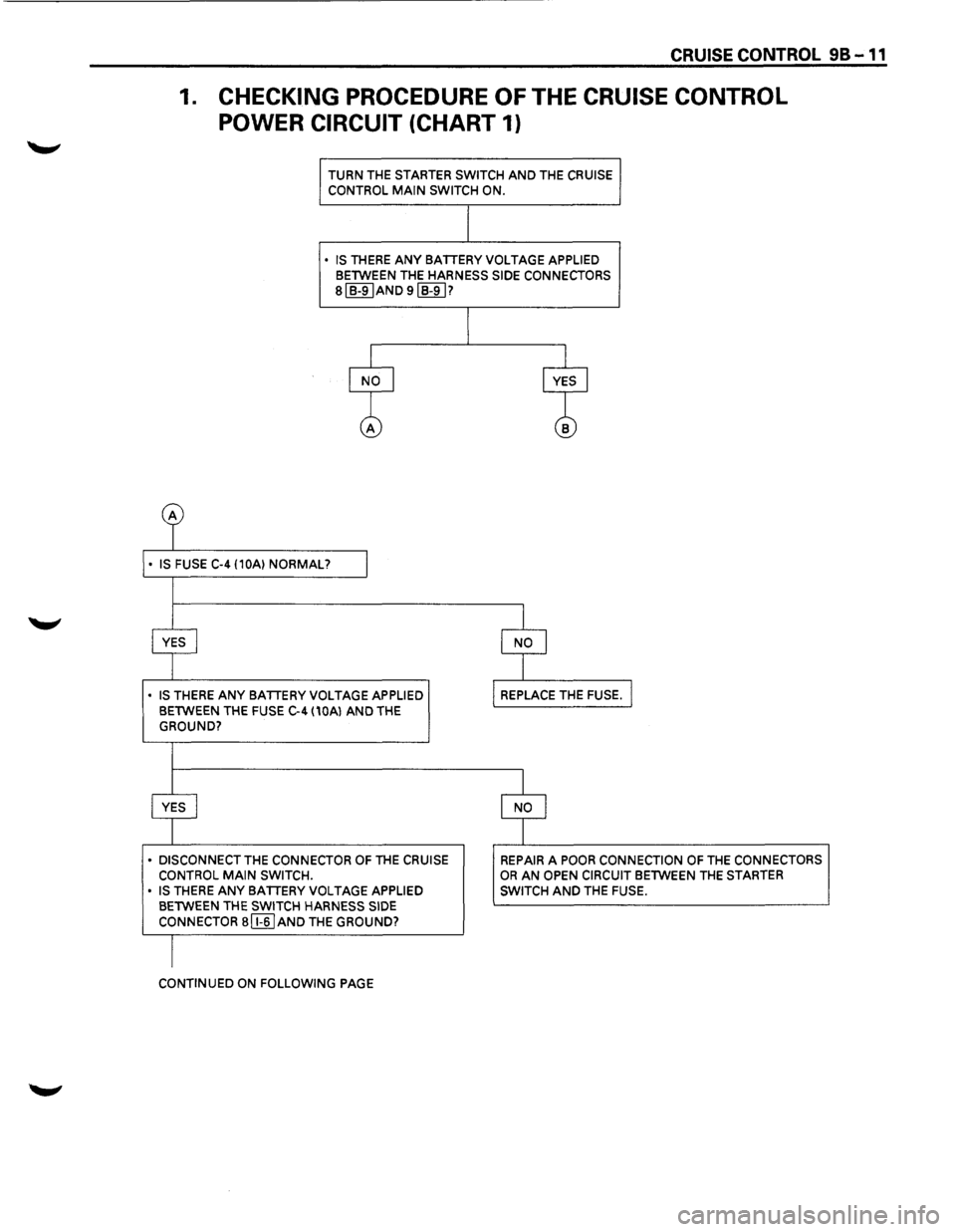
1. CHECKING PROCEDURE OF THE CRUISE CONTROL
POWER CIRCUIT
(CHART 1)
TURN THE STARTER SWITCH AND THE CRUISE
CONTROL MAIN SWITCH ON.
• IS THERE ANY BATTERY VOLTAGE APPLIED BETWEEN THE HARNESS SIDE CONNECTORS
sl B-9IAND 9IB-91?
• IS THERE ANY BATTERY VOLTAGE APPLIED
BETWEEN THE FUSE C-4 (10Al AND THE
GROUND?
• DISCONNECT THE CONNECTOR OF THE CRUISE
CONTROL MAIN SWITCH.
• IS THERE ANY BATTERY VOLTAGE APPLIED
BETWEEN THE SWITCH HARNESS SIDE
CONNECTOR a [I§] AND THE GROUND?
CONTINUED ON FOLLOWING PAGE
REPAIR A POOR CONNECTION OF THE CONNECTORS OR AN OPEN CIRCUIT BETWEEN THE STARTER
SWITCH
AND THE FUSE.