cruise control ISUZU TROOPER 1995 Manual PDF
[x] Cancel search | Manufacturer: ISUZU, Model Year: 1995, Model line: TROOPER, Model: ISUZU TROOPER 1995Pages: 1928
Page 1616 of 1928
98-32 CRUISE CONTROL
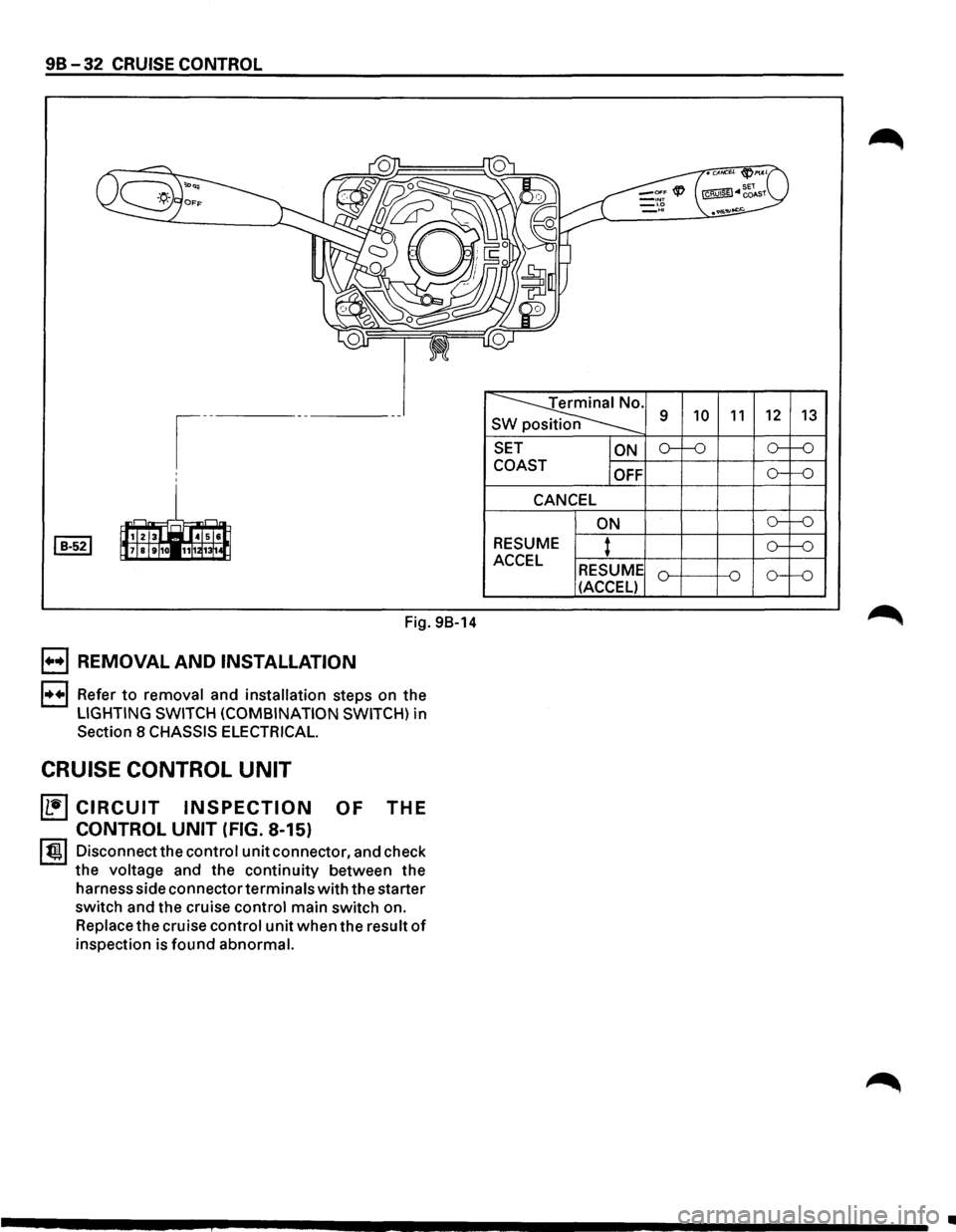
Fig. 98-14
B REMOVAL AND INSTALLATION
l•+l Refer to removal and installation steps on the
LIGHTING SWITCH (COMBINATION SWITCH) in
Section 8 CHASSIS ELECTRICAL.
CRUISE CONTROL UNIT
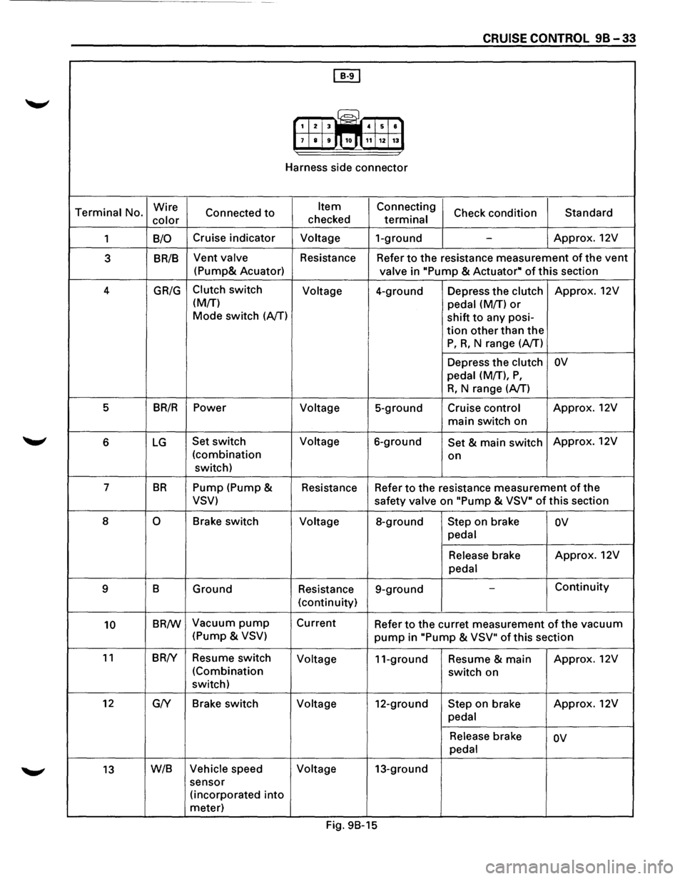
~CIRCUIT INSPECTION OF THE
CONTROL UNIT (FIG. 8-15)
l t!ll Disconnect the control unit connector, and check
the voltage and the continuity between the
harness side connectorterminals with the starter
switch and the cruise control main switch on.
Replace the cruise control unit when the result of
inspection is found abnormal.
~-s
SET
ON
COAST
OFF
CANCEL
ON
RESUME
: ACCEL RESUME
(ACCEL) 9
10 11 12
13
o--'-0 o--f-0
o--f-0
o--'-0
o--'-0
o----o
•
Page 1617 of 1928
CRUISE CONTROL 98-33
[IT]
G?J 1 2 3 iiiill 4 5 8
7 8 9 10.n 11 12 13
Harness side connector
Terminal No. Wire
Connected to Item Connecting
Check condition Standard
color checked terminal
1 B/0 Cruise
indicator Voltage 1-ground -Approx. 12V
3 BR/B Vent valve
Resistance Refer to the resistance measurement of the vent
(Pump& Acuator)
valve in "Pump & Actuator• of this section
4
GR/G Clutch switch
Voltage 4-ground Depress the clutch Approx. 12V
(M/T) pedal (M/T)
or
Mode switch (AfT) shift to any posi-
tion other than the
P, R, N range (A/T)
Depress the clutch
ov
pedal (M/T), P,
R, N range (AfT)
5 BR/R Power
Voltage 5-ground Cruise control Approx.
12V
main switch on
6 LG Set switch Voltage 6-ground Set & main switch Approx.
12V
(combination on
switch)
7
BR Pump (Pump &
Resistance Refer to the resistance measurement of the
VSV) safety valve on "Pump & VSV" of this section
8
0 Brake switch Voltage 8-ground Step on brake ov
pedal
Release brake Approx.
12V
pedal
9 B Ground Resistance 9-ground
-Continuity
(continuity)
10 BR/W Vacuum pump Current
Refer to the curret measurement of the vacuum
(Pump &
VSV) pump in "Pump & VSV" of this section
11 BR!Y Resume switch
Voltage 11-ground Resume & main Approx.
12V
(Combination switch on
switch)
12 G/Y Brake
switch
Voltage 12-ground Step on brake Approx.
12V
pedal
Release brake ov
pedal
13 W/B Vehicle speed Voltage 13-ground
sensor (incorporated
into
meter)
Fig. 9B-15
Page 1618 of 1928
98-34 CRUISE CONTROL
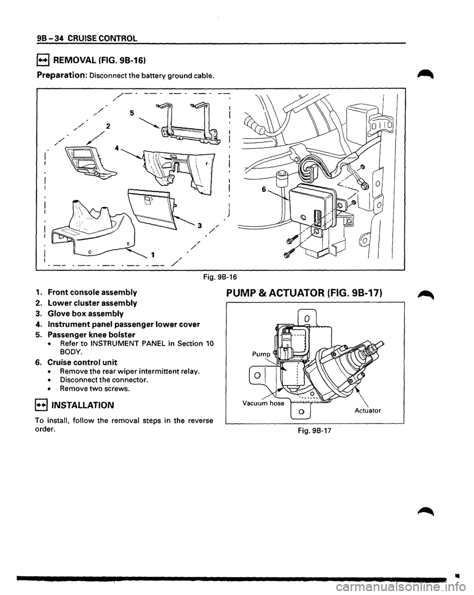
B REMOVAL (FIG. 98-16)
Preparation: Disconnect the battery ground cable.
/-----/
I
J
Fig. 98-16
1. Front console assembly
2. Lower cluster assembly
3. Glove box assembly
4. Instrument panel passenger lower cover
5. Passenger knee bolster
• Refer to INSTRUMENT PANEL in Section 10
BODY.
6. Cruise control unit
• Remove the rear wiper intermittent relay.
• Disconnect the connector.
• Remove two screws.
E) INSTALLATION
To install, follow the removal steps in the reverse
order.
PUMP & ACTUATOR (FIG. 98-17)
Actuator
Fig. 98-17
..
Page 1619 of 1928
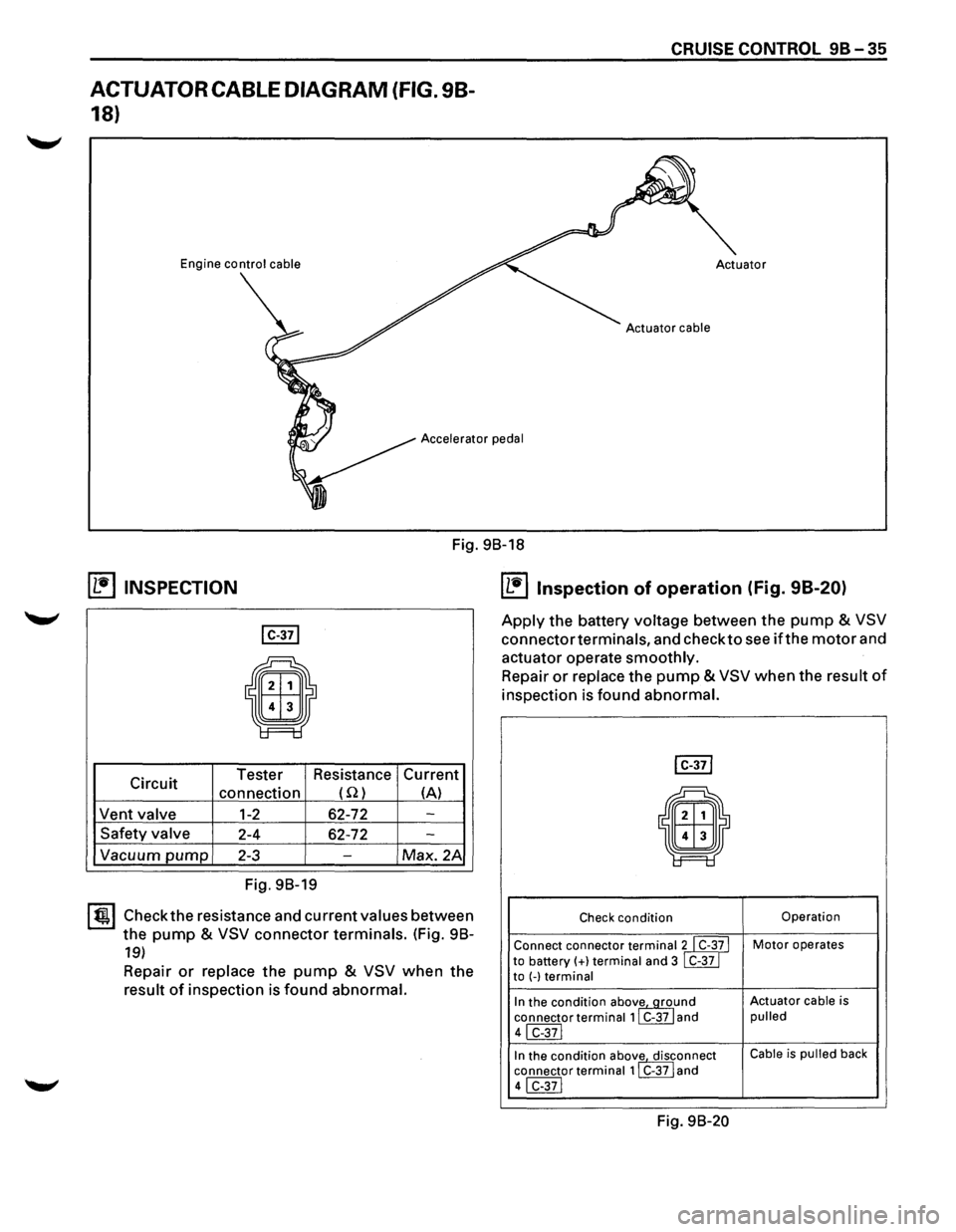
ACTUATOR CABLE DIAGRAM (FIG. 98-
18)
Engine control cable
CRUISE CONTROL 9B-35
Accelerator pedal
Fig. 98-18
~ INSPECTION
I C-371
E9
Circuit Tester
Resistance Current
connection (Q) (A)
Vent
valve 1-2 62-72 -
Safety valve 2-4 62-72 -
Vacuum pump 2-3 -Max. 2A
Fig. 98-19
I~~ Check the resistance and current values between
the
pump & VSV connector terminals. (Fig. 98-
19)
Repair or replace the pump & VSV when the
result of inspection is found abnormal.
IL1i'llnspection of operation (Fig. 98-20)
Apply the battery voltage between the pump & VSV
connector terminals, and check to see if the motor and
actuator operate
smoothly.
Repair or replace the pump & VSV when the result of
inspection is found abnormal.
I C-371
il
Check condition Operation
Connect connector
terminalll C-3~ I Motor operates
to battery(+} terminal and 3 C-37 to (-)terminal
In the condition abov~und Actuator cable is
connector
terminal 1 C-37 and pulled
41 C-371
In the condition abov
1e. disrnnect Cable is pulled back
connector
terminal 1 C-37 and
41 C-371
Fig. 98-20
Page 1620 of 1928
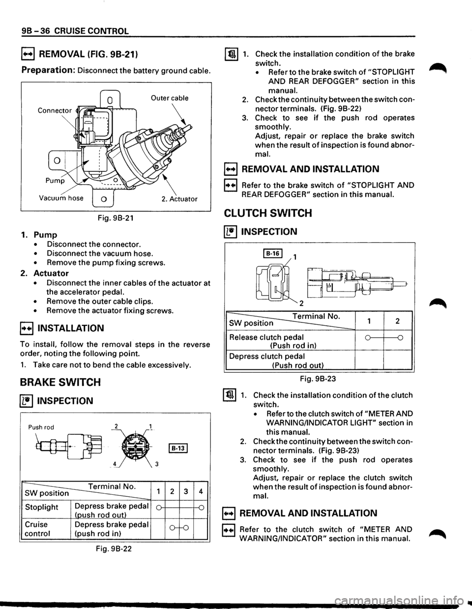
9B-36 CRUISE CONTROL
B REMOVAL (FIG. 98-21)
Preparation: Disconnect the battery ground cable.
Vacuum hose
Fig. 98-21
1. Pump
• Disconnect the connector.
• Disconnect the vacuum hose.
• Remove the pump fixing screws.
2. Actuator
• Disconnect the inner cables of the actuator at
the accelerator
pedal.
•
Remove the outer cable clips.
• Remove the actuator fixing screws.
E) INSTALLATION
To install, follow the removal steps in the reverse
order, noting
the following point.
1. Take care not to bend the cable excessively.
BRAKE SWITCH
~ INSPECTION
2 1
Push rod
~
~'
s ~ 1
Stoplight Depress brake pedal
(oush rod out)
Cruise Depress brake
pedal
control (push rod in)
Fig. 98-22
I B-131
2 3
o--o
4
~1. Check the installation condition of the brake
switch.
• Refer to the brake switch of "STOPLIGHT
AND REAR DEFOGGER" section in this
manual.
2. Check the continuity between the switch con
nector terminals. (Fig. 98-22)
3. Check to see if the push rod operates
smoothly. Adjust, repair
or replace the brake switch
when the result
of inspection is found abnor
mal.
B REMOVAL AND INSTALLATION
1·++·1 Refer to the brake switch of "STOPLIGHT AND
REAR DEFOGGER" section in this manual.
CLUTCH SWITCH
~INSPECTION
I B-161 1
rnll2a-~~
~ s 1 2
Release clutch pedal 0 ~ ~
(Push rod in)
Depress
clutch pedal
~1.
(Push rod out)
Fig. 98-23
Check the installation
condition of the clutch
switch.
• Refer to the clutch switch of "METER AND
WARNING/INDICATOR LIGHT" section in
this
manual.
2. Check the continuity between the switch con
nector terminals. (Fig. 98-23)
3. Check to see if the push rod operates
smoothly. Adjust, repair
or replace the clutch switch
when the result of inspection is found abnor
mal.
B REMOVAL AND INSTALLATION
1••1 Refer to the clutch switch of "METER AND ...-...
WARNING/INDICATOR"
section in this manual. ,...........
Page 1621 of 1928
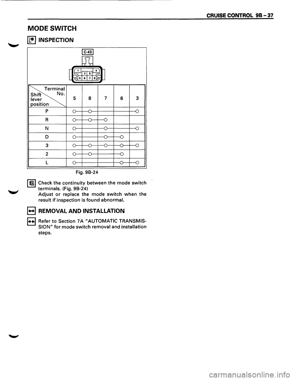
MODE SWITCH
[1!) INSPECTION
5
p 0
R
N
0
D 3
0
2
L
8
Fig. 98-24
7 6 3
lt!tl Check
the continuity between the mode switch
terminals. (Fig. 98-24)
Adjust
or replace the mode switch when the
result if inspection is found abnormal.
B REMOVAL AND INSTALLATION
1++1 Refer to Section 7A "AUTOMATIC TRANSMIS
SION"
for mode switch removal and installation
steps.
CRUISE CONTROL 98-37
Page 1622 of 1928
![ISUZU TROOPER 1995 Manual PDF 98-38 CRUISE CONTROL
VEHICLE SPEED SENSOR (INCORPO
RATED IN SPEEDOMETER)
(1!] INSPECTION
GND GND
SEN 4P
~
I Red(+) Black(-) Black(-) Red(+)
a
I
4P GND 4P GND
4P-GND
13.5K-16.5K 00
Note:](/img/61/57183/w960_57183-1621.png "ISUZU TROOPER 1995 Manual PDF 98-38 CRUISE CONTROL
VEHICLE SPEED SENSOR (INCORPO
RATED IN SPEEDOMETER)
(1!] INSPECTION
GND GND
SEN 4P
~
I Red(+) Black(-) Black(-) Red(+)
a
I
4P GND 4P GND
4P-GND
13.5K-16.5K 00
Note:")
98-38 CRUISE CONTROL
VEHICLE SPEED SENSOR (INCORPO
RATED IN SPEEDOMETER)
(1!] INSPECTION
GND GND
SEN 4P
~
I Red(+) Black(-) Black(-) Red(+)
a
I
4P GND 4P GND
4P-GND
13.5K-16.5K 00
Note: Use an analog type circuit tester.
Fig. 98-25
~~~ Removethespeedometerfromthemeterassem-DIODE
bly, and measure the resistance value between
the
terminals. (Fig. 98-26) IL•IINSPECTION
Replace the speedometer assembly when the
result of inspection is found abnormal.
B REMOVAL AND INSTALLATION
1•+1 Refer to Section 8 "METER AND WARNING/
INDICATOR LIGHT"
for vehicle speed sensor
removal and installation steps.
I B-451
~
Terminal No. 1 2
Connection A
G 0
pattern
0 G 8
Fig.
98-26
I~~ There should be continuity in either A or 8 when
a circuit tester is connected
with diode terminal.
(Fig. 98-26)
Replace the diode when the result of inspection
is
found abnormal.
..
Page 1623 of 1928
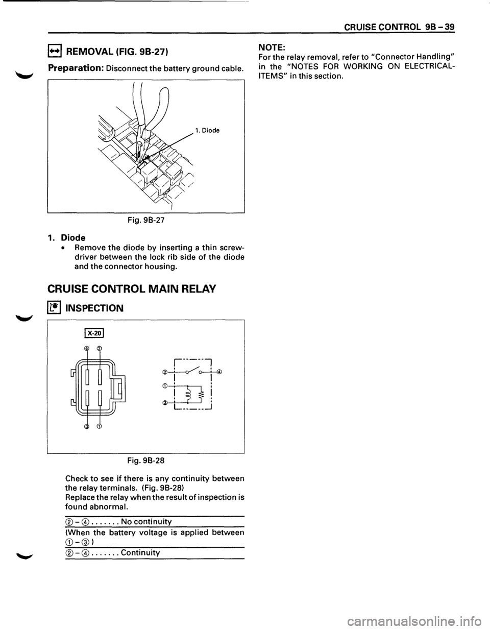
B REMOVAL (FIG. 98-27)
Preparation: Disconnect the battery ground cable.
1. Diode
Fig. 98-27
1. Diode
• Remove the diode by inserting a thin screw
driver between the lock rib side of the diode
and the connector housing.
CRUISE CONTROL MAIN RELAY
~ INSPECTION
@ ®
,-----,
®~~ I I
Q)~!
~J___l___J . L _____ _j
Fig. 98-28
Check
to see if there is any continuity between
the
relay terminals. (Fig. 98-28)
Replace the relay when the result of inspection is
found abnormal.
®-@ ....... No continuity
(When the battery voltage is applied between
CD-®l
®-@ ....... Continuity
CRUISE CONTROL 98-39
NOTE:
For the relay removal, refer to "Connector Handling"
in the "NOTES FOR WORKING ON ELECTRICAL
ITEMS"
in this section.