cruise control ISUZU TROOPER 1995 User Guide
[x] Cancel search | Manufacturer: ISUZU, Model Year: 1995, Model line: TROOPER, Model: ISUZU TROOPER 1995Pages: 1928
Page 999 of 1928
AUTOMATIC TRANSMISSION (4L30-E) 7A-127
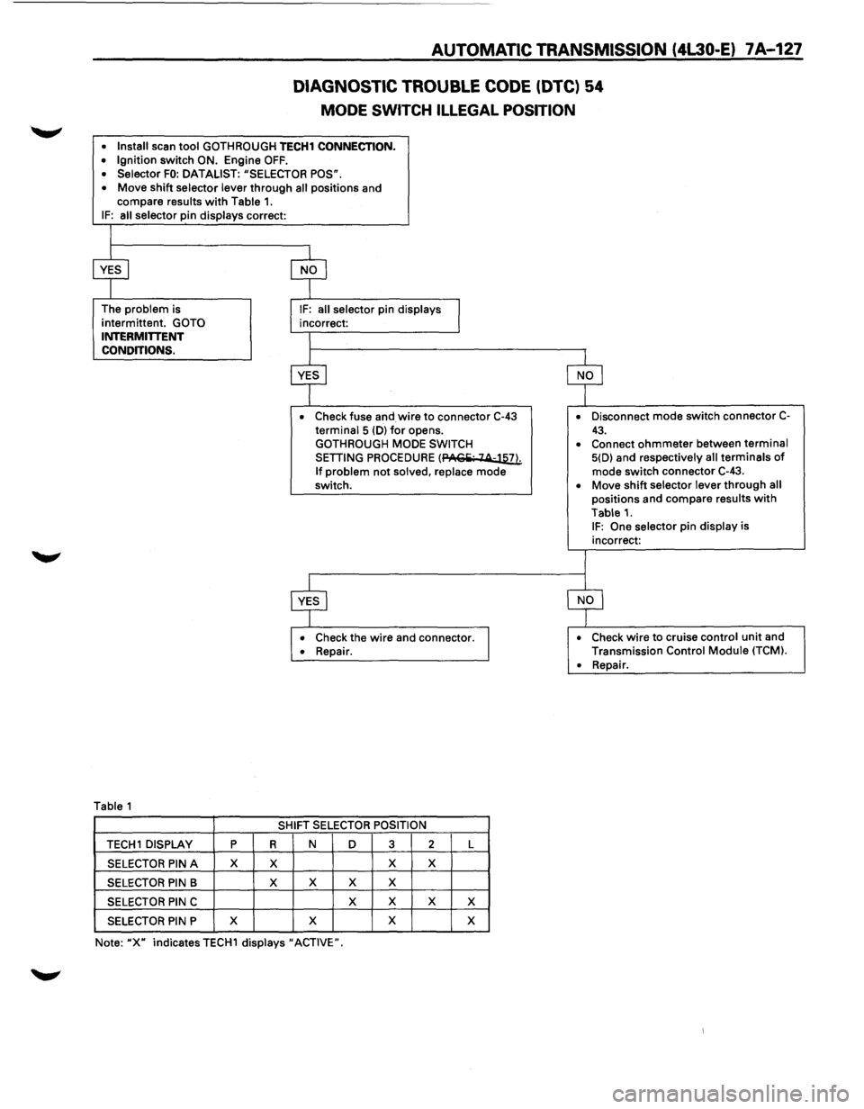
DIAGNOSTIC TROUBLE CODE (DTC) 54
MODE SWITCH ILLEGAL POSITION
• Install scan tool GOTH ROUGH TECH1 CONNECTION. • Ignition switch ON. Engine OFF. • Selector FO: DATALIST: "SELECTOR POS".
• Move shift selector lever through all positions and
compare results with Table 1. IF: all selector pin displays correct:
The
problem is
intermittent.
GOTO INTERMITTENT
CONDITIONS.
Table 1
• Check fuse and wire to connector C-43 terminal 5 (D) for opens.
GOTHROUGH MODE SWITCH
SETTING PROCEDURE (PACiii· 14-llli
If problem not solved, replace mode
switch.
• Check the wire and connector. • Repair.
SHIFT SELECTOR POSITION
TECH 1 DISPLAY p R N D 3 2 L
SELECTOR PIN A X X X X
SELECTOR PIN B X
X X X
SELECTOR PIN C X
X X X
SELECTOR PIN P X
X X
X
Note: "X" indicates TECH1 displays" ACTIVE". •
Disconnect
mode switch connector C-
43. • Connect ohmmeter between terminal 5(D) and respectively all terminals of mode switch connector C-43.
• Move shift selector lever through all positions and compare results with
Table 1. IF: One selector pin display is
incorrect:
• Check wire to cruise control unit and
Transmission Control Module (TCM).
•
Repair.
Page 1000 of 1928
7A-128 AUTOMATIC TRANSMISSION (4L30-E)
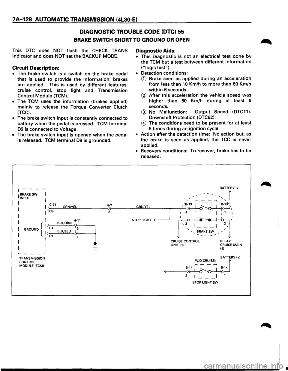
DIAGNOSTIC TROUBLE CODE (DTC) 55
BRAKE SWITCH SHORT TO GROUND OR OPEN
This DTC does NOT flash the CHECK TRANS
indicator and does NOT set the BACKUP MODE.
Circuit Description:
• The brake switch is a switch on the brake pedal
that is used to provide the information: brakes
are
applied. This is used by different features:
cruise control, stop
light and Transmission
Control Module (TCM).
•
The TCM uses the information (brakes applied)
mainly to release the Torque Converter Clutch
(TCC).
•
The brake switch input is constantly connected to
battery when the pedal is pressed. TCM terminal
D9 is connected to Voltage.
• The brake switch input is opened when the pedal
is released.
TCM terminal D9 is grounded.
r----
IBRAKESW I INPUT I
I I C-91 GRN/YEL H-7 I >-D9--~~~------~<
I II a
II
I GROUND I C1 I { }
I I >D1
I I
I I ._ ___ j
TRANSMISSION
CONTROL
MODULE (TCM) BLK!ORN
~-11
B~LU~q
Diagnostic
Aids:
• This Diagnostic is not an electrical test done by
the TCM but a test between different information
("logic test").
• Detection conditions:
CD Brake seen as applied during an acceleration
from less than 10 Km/h to more than 60 Km/h
within 6 seconds.
@ After this acceleration the vehicle speed was
higher than 60 Km/h during at least 6
seconds.
@ No Malfunction: Output Speed (DTC11 ).
Downshift Protection (DTC62).
@ The conditions need to be present for at least
5
times during an ignition cycle.
• Action after the detection time: No action but, as
the brake is seen as applied, the TCC is never
applied.
• Recovery conditions: To recover, brake has to be
released.
CRUISE CONTROL UNIT(8) RELAY
CRUISE MAIN (4)
BATTERY(+)
!'~~s:_ d B-14 ~ _ I _B-14 ~--<~~
2 L--_I 1
STOP LIGHT SW
•
Page 1002 of 1928
7A-130 AUTOMATIC TRANSMISSION (4l30-E)
DIAGNOSTIC
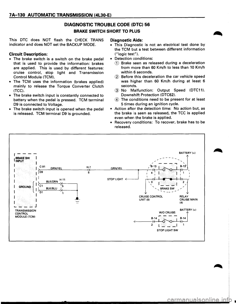
TROUBLE CODE (DTC)·56
BRAKE SWITCH SHORT TO PLUS
This DTC does NOT flash the CHECK TRANS
indicator and does
NOT set the BACKUP MODE.
Circuit Description:
• The brake switch is a switch on the brake pedal
that is used to provide the information: brakes
are
applied. This is used by different features:
cruise
control, stop light and Transmission
Control Module (TCM).
•
The TCM uses the information (brakes applied)
mainly to release the Torque Converter Clutch
(TCC).
• The brake switch input is constantly connected to
battery when the pedal is pressed. TCM terminal
D9 is connected to Voltage.
•
The brake switch input is opened when the pedal
is released. TCM terminal D9 is grounded.
r----
IBRAKESW I INPUT I
I I C-91 GRN!YEL H-7 I lf~D-9--~~~------~~
I II I
I GROUND { 1 ?c1 II I >o1
I I
I I
.._ ___ J
TRANSMISSION
CONTROL
MODULE (TCM)
H-11
BLK!ORN sq
BLK!BLU ~
1
Diagnostic Aids:
• This Diagnostic is not an electrical test done by
the TCM but a test between different information
("logic test").
•
Detection conditions:
CD Brake seen as released during a deceleration
from more than 60 Km/h to less than 10 Km/h
within 6 seconds.
® Before this deceleration the car vehicle speed
was
higher than 60 Km/h during at least 6
seconds.
@ No Malfunction: Output Speed (DTC11).
Downshift Protection (DTC62).
@ The conditions need to be present for at least
5 times; during an ignition cycle.
•
Action atte~r the detection time: No action but, as
the brake is seen as released, the TCC is applied
even when the brake is applied.
•
Recovery conditions: To recover, brake has to be
released.
BATTERY(+)
,.------, d / '
GRN/YEL I /~;3 I ~-~3' I
~4 I I 1 I
STOP LIGHT <0---.Jr ~~l/ \3 1 ___ , 2/
' / ' BRAKE SW ,. .......... -----.......
CRUISE CONTROL UNIT(8) RELAY CRUISE MAIN (4)
BATTERY(+)
~~~R~s:_ d
·:.:-: ---~~~-14
2 L--_I 1
STOP LIGHT SW
•
Page 1022 of 1928
7A-150 AUTOMATIC TRANSMISSION (4L30-E)
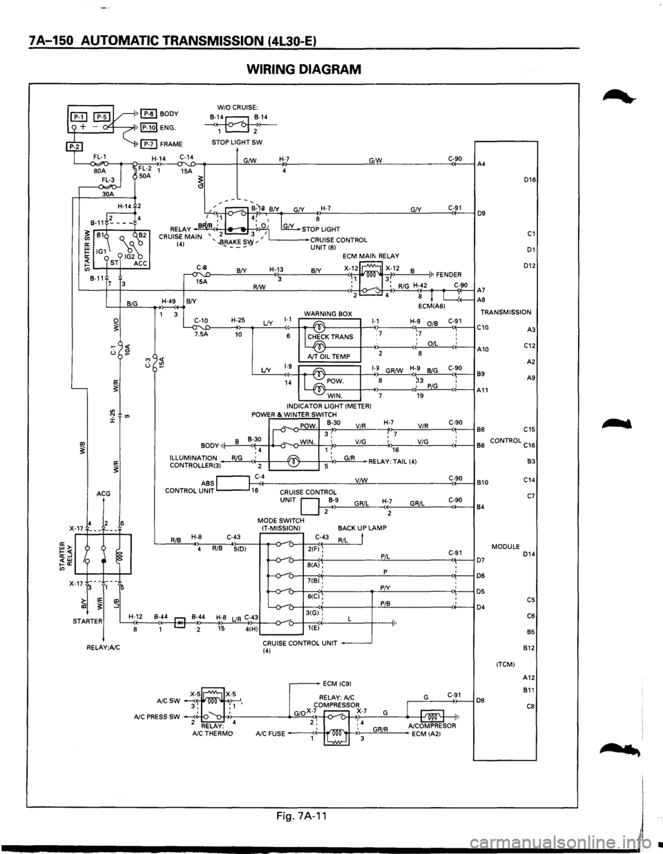
WIRING DIAGRAM
L--<~o-~~~~~~--~~~----~~~----~~--------------~G"IW~------------C«-9_0--iA4
D16
30A
D12
GfY ---~:at--B-'li BfY G(Y H-7 ,...-..~., 4,' ~ ~
RELAY ~' ~:iO 1 [my_ STOP LIGHT
2 3 I CRUISE MAIN '..BRAKES '' L------•CRUISE CONTROL (4) - ---vy UNIT (8) D1
~2
8-11+~---f4
~ 81~ Q._ ("'~2
~ IG1 18~ ~ ST ACC en 8-11
C-91 D9
C1
ECM MAIN RELAY
X-f~ ~X~~2 8 II• FENDER R/W : - : RiG H-42 C-90 '-----t--t------+-------!:!Lll----------< • ~( r fl A7 2 4 8 L....{+--AS
C-8
~A
H-13 BfY BfY 3 7 3
L-+-JB~~I,_IG __ __....,~4-B(Y ECM(A61 1 3 WARNING BOX TRANSMISSION
~T'~5'-'1:D----H-+~2~5 LfY ~~~ ~K TRANS 1-,17 Hr7 :~ C-~1 C10 C::
0 ~
"' <( u :!?
'----~
"' ":' 0'> J:
IXl ~ a: ~
I~ A10 AJT OIL TEMP 2
8
A
2
LfY 1-9~ ~1-9 GR/W H;9 BiG C-90 89 1~ POW. : 8 ~3 , A9
- -~· PiG c(-A11 WIN. 7 19 INDICATOR LIGHT (METER) POWER & WINTER SWITCH
_,. POW. 8-30 ViR H-,>,7:;-----'V"-'iR.!..,_ ___ c<-~9-0-l B8 C15 II-v 3, :7 • BODY of~~ ~-o-WIN. 1 ,' ViG -----.+.,.,176 __ ____;;V.:..;iG=-----<+'-----1 B
6 CONTROL C16 ,4 ILLUMINATION~' ~ '~RELAY: TAIL (4) CONTROLLER(3) 2 -~ 5
ABS ~c~4----------------__yV:J..:!:!._/W ______________ ___:C<-~9:..::0-l B 10 CONTROL UNIT 16 CRUISE CONTROL
RiB H-8 C-43
4 RiB 5(D)
UNIT Q;·>-9------"G,_,Ri_,L_~:+--;-----'G""R""iL::,_ ___ c,-+-9-0----j 84
MODE SWITCH
IT-MISSION)
C-43
2(F) ~ ' 8(A), '
BACKUP LAMP
RiL
t
PiL
p
C-91 ( D7 : D6
B3
C14
C7
MODULE D14
: D5 : C5 ( D4 C6
B5
7(B)'
X-17-l-~J,-~L -v-: 6((:1§': :
r! -v-u-3tGi'', STARTER H-~..._:4---4r::J-Mo~-_B~;~;8 LJR C;~434--o-_,_-o---+---<·' L ---1 8 1 [::::J 2 15 4(H) u---~< 1 '
CRUISE CONTROL UNIT RELAY;A/C (4)
DB
(TCM) 812
A12
811
C8
....
'
Fig.7A·11 I
------------------------~~
•
Page 1191 of 1928

CHASSIS ELECTRICAL 8-1
·SECTION 8
CHASSIS ELECTRICAL
'\f CAUTION: .
When fasteners are removed, always reinstall them at the same location from which they were removed.
If a fastener needs to be replaced, use the correct part number fastener for that application. If the correct
part number fastener is not
available, a fastener of equal size and strength (or stronger) may be used.
Fasteners that are not reused, and those requiring thread
locking compound, will be called out. The correct
torque
values must be used when installing fasteners that require it. If the above conditions are not
followed, parts or system damage could result.
CONTENTS
General Information .................................... 8-2
Notes for Working on Electrical
Items .................................................... 8-2
Symbols and Abbreviations ................. 8-8
Symbols ............................................ 8-8
Abbreviations ................................... 8-9
Parts for Electrical Circuit ..................... 8-10
Wiring ............................................... 8-10
Fuse .................................................. 8-11
Fusible Link ....................................... 8-12
Circuit Breaker ................................... 8-12
Relay ................................................. 8-12
Relay Specifications and
Configurations ................................ 8-13
Diode ................................................. 8-14
Connector ......................................... 8-15
Reading the Circuit Diagram ................ 8-17
Main Data and Specifications .................... 8-19
Bulb Specifications ................................ 8-19
Fuse,
Fusible Link and
Circuit Breaker Location ..................... 8-21
Fuse
Block Circuit .................................. 8-22
Reference Table of Fuse, Fusible
Link and Circuit Breaker ..................... 8-23
Relay Location ....................................... 8-27
Diode Location .......................................
8-28
Grounding Point .................................... 8-29
Reference Table ................................ 8-29
Location ............................................ 8-31
Cable Harness Routing .......................... 8-34
System Repair .............................................. 8-38
Start and Charging ................................ 8-38
Engine Control Module
(ECM) ................................................... 8-47
Headlight and Fog Light ........................ 8-58
Front Side Marker Light, Parking Light,
Taillight, License Plate Light and
Illumination Light .............................. 8-76
Stoplight and Rear Defogger .............. 8-92
Turn Signal Light, Hazard
Warning
Light, Cornering Light,
Backup
Light and Horn ..................... 8-106
Dome Light, Luggage room Light,
Courtesy Light, Map Light,
Seat Belt Switch and
Warning Buzzer ................................. 8-128
Power Door Lock ................................. 8-142
Power
Window .................................... 8-156
Cruise
Control ...................................... 8-172
Anti-Lock Brake
System (ABS) ........... 8-178
Rear
Wheel Anti-Lock Brake
System (RWAL) ................................. 8-185
Transmission
Control Module
(TCM) ................................................. 8-192
A/T Shift Lock ...................................... 8-200
Windshield
Wiper/Washer and
Rear
Wiper/Washer .......................... 8-205
Headlight wiper /washer ..................... 8-232
Audio, Auto Antenna,
Cigarette
Lighter and digital clock ... 8-246
Power Door Mirror ............................... 8-254
Anti-theft System ................................ 8-270
Meter and Warning/Indicator Light ... 8-288
A/T Shift Indicator ............................... 8-336
Heater and
Air Conditioning ............... 8-340
Sun
Roof ............................................... 8-346
Power Seat ........................................... 8-360
Seat
Heater .......................................... 8-37 4
Supplemental Restraint
System (SRS) -AIR BAG ................... 8-382
Page 1207 of 1928
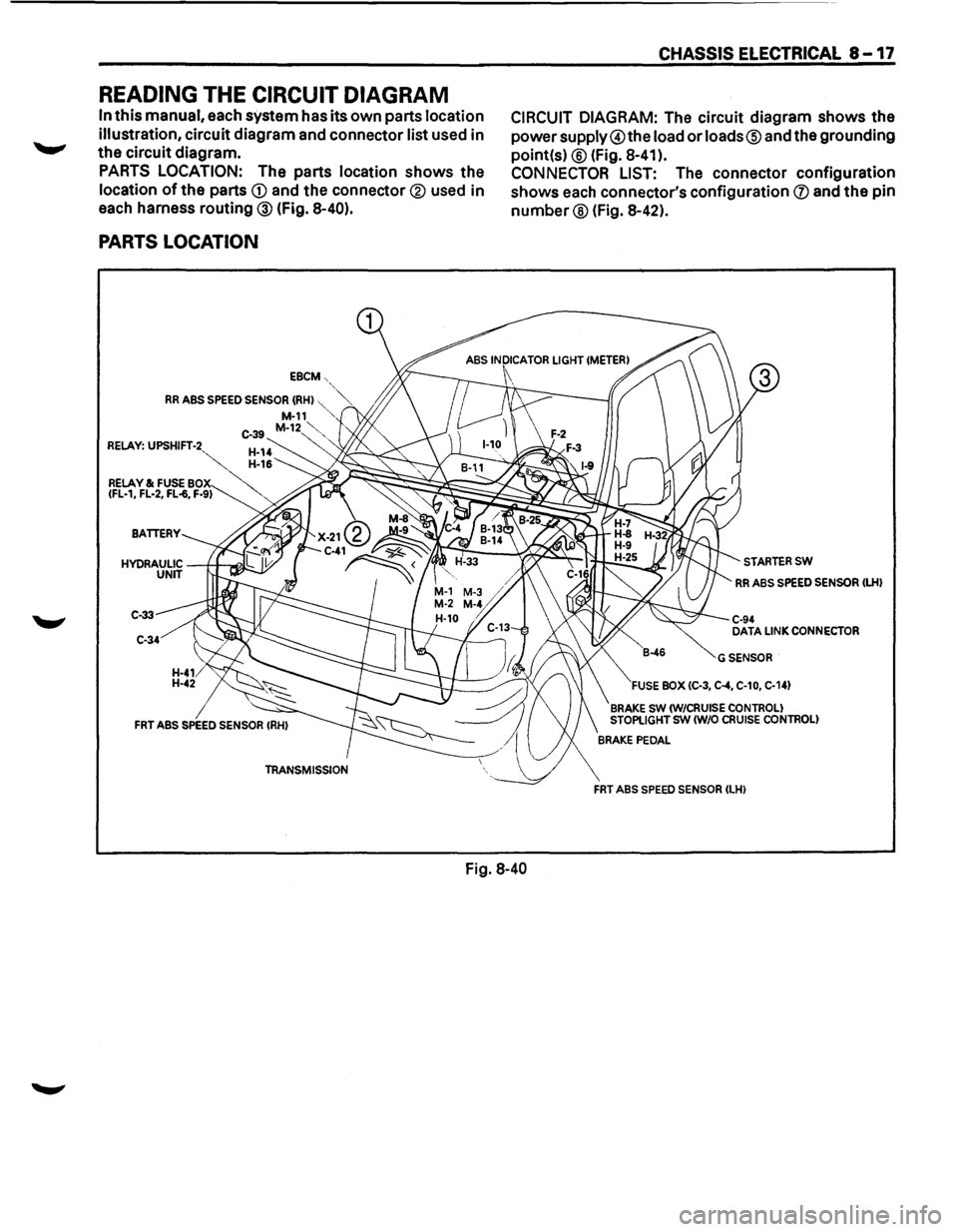
READING THE CIRCUIT DIAGRAM
In this manual, each system has its own parts location
illustration,
circuit diagram and connector list used in
the circuit diagram.
PARTS LOCATION: The parts location shows the
location of the parts CD and the connector® used in
each harness routing ® (fig. 8-40).
PARTS LOCATION
EBCM-,
RR ABS SPEED SENSOR (RHI "',~ M-11 ,,
C-39 M-12~'-, RELAY: UPSHIFT-2 ~
CHASSIS ELECTRICAL 8-17
CIRCUIT DIAGRAM: The circuit diagram shows the
powersupply@the load or loads® and the grounding
point(s)
® (Fig. 8-41 ).
CONNECTOR LIST: The connector configuration
shows
each connector's configuration (J) and the pin
number® (Fig. 8-42).
RELAY & FUSE BO~"'
7
~<-:;;;:~:~:_::0:;;::::'=l-\,.-..:._::::;;,...6
IFL-1, FL-2, FL-6, F-91 , "" ;;~~~~~~~;g~~k~
C-33
C-34
Fig. 8-40
STARTERSW
RR ABS SPEED SENSOR ILHI
C-94 DATA LINK CONNECTOR
GSENSOR
FUSE BOX IC-3, C-4, C-10, C-141
BRAKE SW IW/CRUISE CONTROL! STOPLIGHT SW (W/0 CRUISE CONTROL!
FRT ABS SPEED SENSOR ILHI
Page 1210 of 1928
8-20 CHASSIS ELECTRICAL
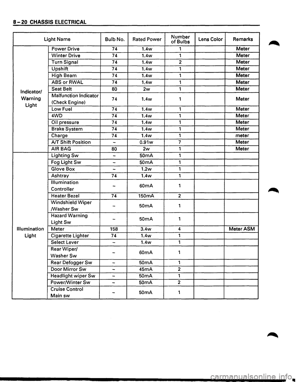
Light Name Bulb No. Rated Power Number Lens Color Remarks of Bulbs
Power Drive 74 1.4w 1
Meter
Winter Drive 74 1.4w
1 Meter
Turn Signal 74 1.4w 2 Meter
Upshift
74 1.4w 1 Meter
High Beam
74 1.4w 1 Meter
ABSorRWAL 74 1.4w 1 Meter
Indicator/ Seat Belt 80 2w 1 Meter
Warning Malfunction Indicator 74 1.4w
1 Meter
Light (Check
Engine)
Low Fuel 74 1.4w 1 Meter
4WD
74 1.4w 1 Meter
Oil pressure 74 1.4w 1 Meter
Brake System 74 1.4w 1 Meter
Charge 74 1.4w 1
meter
A/T Shift Position -0.91w 7 Meter
AIR BAG 80 2w 1 Meter
Lighting Sw -SOmA 1
Fog Light
Sw -SOmA 1
Glove Box -1.2w 1
Ashtray
74 1.4w 1
Illumination
60mA 1 -Controller
Heater Bezel 74 1SOmA 2
Windshield
Wiper SOmA 1 -/WasherSw
Hazard Warning SOmA 1 -Light Sw
Illumination Meter 158 3.4w 4 MeterASM
Light
Cigarette Lighter
74 1.4w
1
Select Lever -1.4w 1
Rear
Wiper/ 60mA 1 -WasherSw
Rear Defogger Sw -SOmA 1
Door
Mirror Sw -45mA 2
Headlight
wiper Sw -SOmA 1
Power/Winter
Sw -SOmA 2
Cruise Control
SOmA 1 -Main sw
II
Page 1213 of 1928
CHASSIS ELECTRICAL 8-23
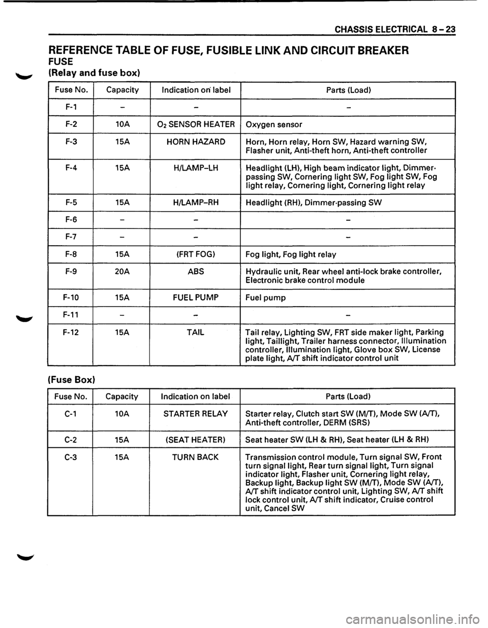
REFERENCE TABLE OF FUSE, FUSIBLE LINK AND CIRCUIT BREAKER
FUSE
'--"' (Relay and fuse box)
Fuse No. Capacity
Indication on· label Parts (Load)
F-1 --
-
F-2 10A 02 SENSOR HEATER Oxygen sensor
F-3 15A HORN HAZARD Horn, Horn relay, Horn SW, Hazard warning SW,
Flasher
unit, Anti-theft horn, Anti-theft controller
F-4 15A
H/LAMP-LH Headlight (LH), High beam indicator light, Dimmer·
passing SW, Cornering light SW, Fog light SW, Fog
light relay, Cornering light, Cornering light relay
F-5 15A
H/LAMP-RH Headlight (RH), Dimmer·passing SW
F-6 ---
F-7 --
-
F-8 15A (FRT FOG) Fog light, Fog light relay
F-9 20A ABS Hydraulic unit, Rear wheel anti-lock brake controller,
Electronic brake control module
F-10 15A FUEL PUMP
Fuel pump
F-11 ---
F-12 15A TAIL Tail
relay, Lighting SW, FRT side maker light, Parking
light, Taillight, Trailer harness connector, Illumination
controller, Illumination light, Glove
box SW, License
plate light, A/T shift indicator control unit
(Fuse Box)
Fuse No. Capacity
Indication on label Parts (Load)
C-1 10A STARTER RELAY Starter relay, Clutch start SW (M/T), Mode SW (A/T),
Anti-theft controller, DERM (SRS)
C-2 15A (SEAT
HEATER) Seat heater SW (LH & RH), Seat heater (LH & RH)
C-3 15A TURN BACK Transmission control module, Turn signal SW, Front
turn signal light, Rear turn signal light, Turn signal
indicator light, Flasher unit, Cornering light relay,
Backup light, Backup light SW (M/T), Mode SW (A/T),
A/T shift indicator control unit, Lighting SW, A/T shift
lock control unit, A/T shift indicator, Cruise control
unit, Cancel SW
Page 1214 of 1928
8-24 CHASSIS ELECTRICAL
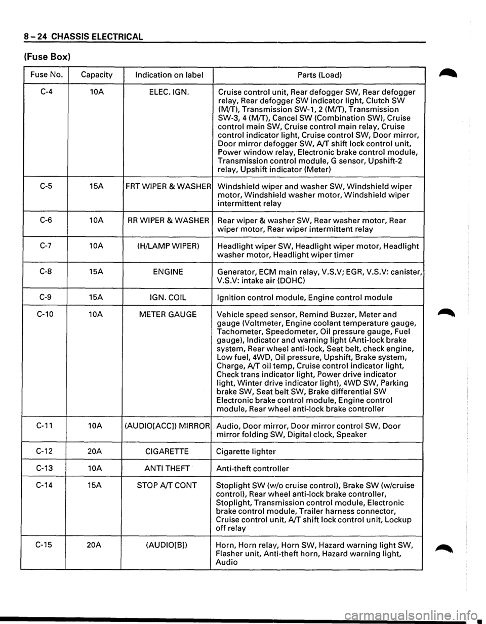
(Fuse Box)
Fuse No.
Capacity Indication on label Parts (Load)
C-4 10A
ELEC.IGN. Cruise control unit, Rear defogger SW, Rear defogger
relay, Rear
defo9ger SW indicator light, Clutch SW
(M{T), Transmission SW-1, 2 (M!T), Transmission
SW-3, 4 (M{T), Cancel
SW (Combination SW), Cruise
control main
SW, Cruise control main relay, Cruise
control indicator light, Cruise control
SW, Door mirror,
Door mirror defogger SW, AfT shift lock control unit,
Power window relay, Electronic brake control module,
Transmission control module, G sensor, Upshift-2
relay, Upshift indicator (Meter)
C-5 15A FRTWIPER &WASHER
Windshield wipt~r and washer SW, Windshield wiper
motor, Windshit~ld washer motor, Windshield wiper
intermittent relay
C-6 10A RR WIPER & WASHER
Rear wiper & washer SW, Rear washer motor, Rear
wiper motor, Rear wiper intermittent relay
C-7 10A (H/LAMP WIPER) Headlight wiper SW, Headlight wiper motor, Headlight
washer motor, Headlight
wiper timer
C-8 15A ENGINE Generator, ECM main relay, V.S.V; EGA, V.S.V: canister,
V.S.V: intake air
(DOHC)
C-9 15A IGN. COIL Ignition control module, Engine control module
C-10 10A METER GAUGE Vehicle speed stmsor, Remind Buzzer, Meter and
gauge
(Voltmeter, Engine coolant temperature gauge,
Tachometer, Speedometer,
Oil pressure gauge, Fuel
gauge),
Indicator and warning light (Anti-lock brake
system, Rear wheel anti-lock, Seat belt, check engine,
Low fuel, 4WD,
Oil pressure, Upshift, Brake system,
Charge,
AfT oil temp, Cruise control indicator light,
Check trans indicator light,
Power drive indicator
light,
Winter drive indicator light), 4WD SW, Parking
brake SW, Seat belt SW, Brake differential SW
Electronic brake control module, Engine control
module, Rear wheel anti-lock brake controller
C-11 10A (AUDIO[ACCJ) MIRROR Audio, Door mirror, Door mirror control SW, Door
mirror folding SW, Digital clock, Speaker
C-12 20A CIGARETTE Cigarette lighter
C-13 10A
ANTI THEFT Anti-theft controller
C-14 15A
STOP AfT CONT Stoplight SW (w/o cruise control), Brake SW (w/cruise
control), Rear wheel anti-lock brake controller,
Stoplight, Transmission control module, Electronic
brake control module, Trailer harness connector,
Cruise control unit,
AfT shift lock control unit, Lockup
off relay
C-15
20A (AUDIO[B]) Horn,
Horn relay, Horn SW, Hazard warning light SW,
Flasher unit, Anti-theft horn, Hazard warning light,
Audio
•
Page 1217 of 1928
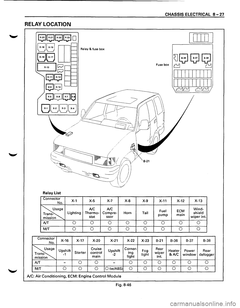
RELAY LOCATION
Relay & fuse box
Relay List
Connector X-1 X-5 X-7
X-8
No.
~
NC NC Lighting Thermo-Com pre-
Horn -stat ssor
n
NT 0 0 0 0
M(f 0 0 0
0
Connector
X-16 X-17 X-20 X-21 X-22
No.
~
Upshift Cruise Upshift Corner-
-1 Starter control -2 ing -main light n
NT -0 0 -0
M!f 0 0 0 0(w/A8S) 0
AJC: Air Conditioning, ECM: Engine Control Module
Fig. 8-46
B-21
X-9
Tail
0
0
X-23
Fog
light
0
0
CHASSIS ELECTRICAL 8-27
Fuse box
X-11
Fuel pump
0
0
8-21
II]]]J I
~8~8
c:J c:J
11111111111
111111
IIIII
BB a B
X-12 X-13
ECM Wind-
main shield wiper int.
0
0
0 0
8-36
8-37
8-38
Rear Heater Power Rear
wiper int. &NC window defogger
0
0 0
0
0 0 0
0