cruise control ISUZU TROOPER 1995 Owner's Manual
[x] Cancel search | Manufacturer: ISUZU, Model Year: 1995, Model line: TROOPER, Model: ISUZU TROOPER 1995Pages: 1928
Page 1218 of 1928
8-28 CHASSIS ELECTRICAL
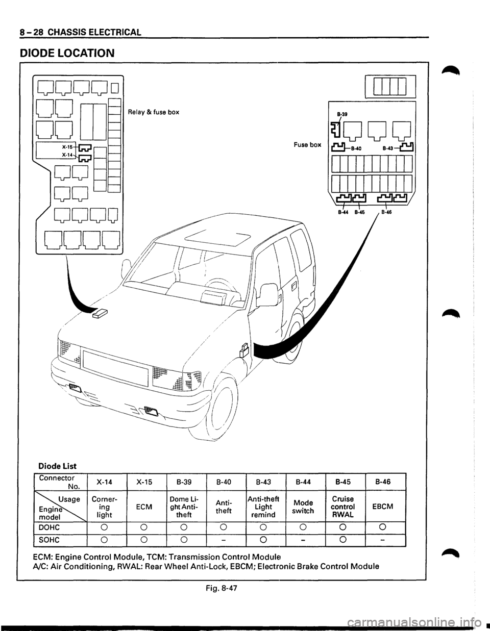
DIODE LOCATION
Relay & fuse box
Fuse box
Diode List
Connector X-14
X-15 B-39 8-40 8-43 8-44
B-45 8-46 No.
~
Corner-Dome Li-Anti-Anti-theft
Mode Cruise ing ECM ghtAnti-
theft Light
switch control EBCM
light
theft remind RWAL
DOHC 0
0 0 0
0 0 0 0
SOHC 0
0 0 -0 -0 -
ECM:
Engine Control Module, TCM: Transmission Control Module1
A/C: Air Conditioning, RWAL: Rear Wheel Anti-Lock, EBCM; Electronic Brake Control Module
Fig. 8-47
•
Page 1219 of 1928
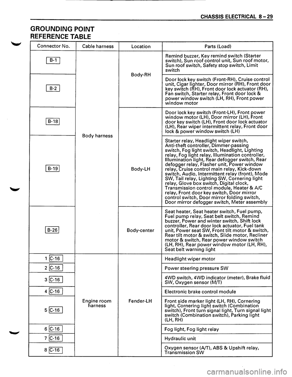
GROUNDING POINT
REFERENCE TABLE
Connector No.
Cable harness
~
~
I B-1a1
Body harness
I B-191
I B-261
1 lc-16 I
2IC-16 I
3IC-16 I
4IC-16 I
Engine room
5IC-16 I
harness
6IC-16 I
7IC-16 I
aiC-16 1
Location
Body-RH
Body-LH
Body-center
Fender-LH
CHASSIS ElECTRICAL 8-29
Parts (Load)
Remind buzzer, Key remind switch (Starter
switch),
Sun roof control unit, Sun roof motor, Sun roof switch, Safety stop switch, Limit
switch
Door lock key switch (Front-RH), Cruise control
unit, Cigar lighter, Door mirror (RH), Front door
key switch (RH), Front door lock actuator (RH),
Fan switch, Starter relay, Front
door lock & power window switch (LH, RH), Front power window motor
Door lock key switch (Front-LH), Front power window motor (LH), Door mirror (LH), Front
door key switch (LH), Front door lock actuator
(LH), Rear wiper intermittent relay, Front door
lock & power window switch (LH)
Starter relay, Headlight
wiper switch,
Anti-theft controller,
Dimmer·passing switch, Fog light switch, Headlight, Lighting
relay, Fog
light relay, Illumination controller,
Illumination light, Rear defogger switch, Rear
defogger relay, Flasher unit,
Power window relay, Cruise control main relay, Kick-down
switch, Audio, Intermittent relay (front), Mode SW, Tail relay, Lighting SW, Cornering light
relay, Glove box switch, Digital clock,
Transmission control module, Heater & A/C
relay, Front
door key switch, Door mirror
control switch, Door mirror folding switch,
Door mirror defogger switch, Meter assembly
Seat heater, Seat heater switch, Fuel pump, Fuel pump relay, Seat belt switch, Remind
buzzer, Power and winter switch, Shift lock
controller, Rear
door lock actuator, Fuel tank
unit, Power seat SW, Front tilt motor & switch,
Rear tilt motor & switch, Slide motor, Recliner
motor & switch, Rear power window switch
(LH, RH), Rear power window motor (LH, RH),
Seat belt warning light
Headlight
wiper motor
Power steering pressure SW
4WD switch, 4WD indicator (meter), Brake fluid
SW, Oxygen sensor (M/T)
Electronic brake control
module
Front side marker light (LH, RH), Cornering
light, Cornering light switch (Combination
switch), Front turn signal light, Turn signal light switch (Combination switch), Parking light (LH, RH)
Fog light, Fog light relay
Hydraulic
unit
Oxygen sensor (AfT), ABS & Upshift relay,
Transmission SW
Page 1220 of 1928
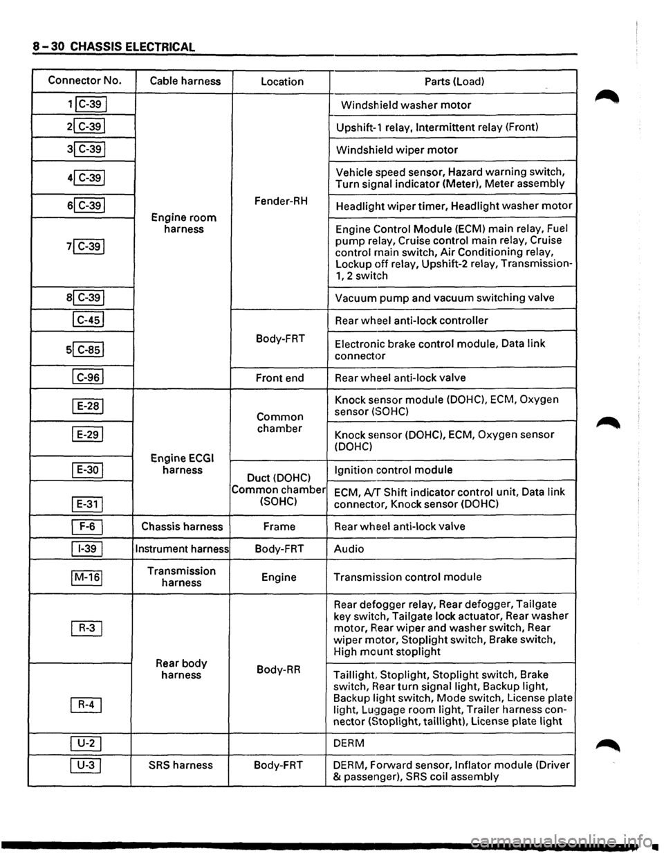
8-30 CHASSIS ELECTRICAL
Connector No.
Cable harness
Location Parts (load)
1jC-39I Windshield washer motor
21 C-391 Upshift-1 relay, Intermittent relay (Front)
31 C-391 Windshield wiper motor
41 C-39j Vehicle speed
sensor, Hazard warning switch,
Turn
signal indicator (Meter), Meter assembly
sl C-391 Fender-RH Headlight wiper timer, Headlight washer motor
Engine room
harness Engine Control Module (ECM)
main relay, Fuel
71 C-391 pump relay, Cruise control main relay, Cruise
control main switch, Air Conditioning relay,
Lockup off relay, Upshift-2 relay, Transmission-
1, 2 switch
al C-391 Vacuum pump and vacuum switching valve
I C-451 Rear wheel anti-lock controller
sl c-asl
Body-FRT Electronic brake control module, Data link
connector
I C-961 Front end Rear wheel
anti-lock valve
I E-281 Knock sEmsor module (DOHC), ECM, Oxygen
Common sensor (SOHC)
I E-291 chamber Knock sensor (DOHC), ECM, Oxygen sensor
(DOHC)
Engine
ECGI
I E-30 I harness Duct (DOHC) Ignition control
module
Common chamber
ECM, AfT Shift indicator control unit, Data link
I
E-311 (SOHC) connector, Knock sensor (DOHC)
~ Chassis harness Frame
Rear wheel anti-lock valve
11-391 Instrument
harness
Body-FRT Audio
IM-161 Transmission
Engine Transmission control module harness
Rear defogger
relay, Rear defogger, Tailgate
~
key switch, Tailgate lock actuator, Rear washer
motor, A:ear wiper and washer switch, Rear
wiper motor, Stoplight switch, Brake switch,
High
mount stoplight
Rear body Body-RR
harness Taillight, Stoplight, Stoplight switch, Brake
switch,
near turn signal light, Backup light,
~
Backup light switch, Mode switch, License plate
light, Lu!;)gage room light, Trailer harness con-
nector
(Stoplight, taillight), License plate light
~ DERM
00 SRS harness Body-FRT
DERM, Forward sensor, Inflator module (Driver
& passenger),
SRS coil assembly
•
Page 1282 of 1928
I
8 -92 CHASSIS ELECTRICAL I
STOPLIGHT AND REAR DEFOGGER I
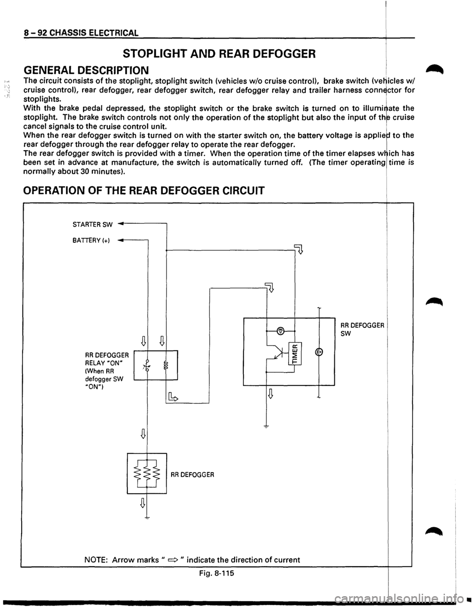
GENERAL DESCRIPTION i .-_
The circuit consists of the stoplight, stoplight switch (vehicles w/o cruise control), brake switch (ve~icles w/
cruise control), rear defogger, rear defogger switch, rear defogger relay and trailer harness conn~ctor for
stoplights. i
With the brake pedal depressed, the stoplight switch or the brake switch is turned on to illumi~ate the
stoplight. The brake switch controls not only the operation of the stoplight but also the input of th~ cruise
cancel signals to the cruise control unit. 1
When the rear defogger switch is turned on with the starter switch on, the battery voltage is applie to the
rear
defogger through the rear defogger relay to operate the rear defogger.
The rear
defogger switch is provided with a timer. When the operation time of the timer elapses w ich has
been set in advance at manufacture,
the switch is automatically turned off. (The timer operating time is
normally about 30 minutes).
OPERATION OF THE REAR DEFOGGER CIRCUIT
STARTER SW ..------,
BATTERY(+)
~----------------0
llJ,
f-®-
RR DEFOGGER
~
SW
~
>'f RR DEFOGGER ~~
RELAY "ON" :4r 2 1-
(When RR ?
defogger SW HON"I
~ [b
RR DEFOGGER
NOTE: Arrow marks II => II indicate the direction of current
Fig. 8-115
~
•
Page 1283 of 1928
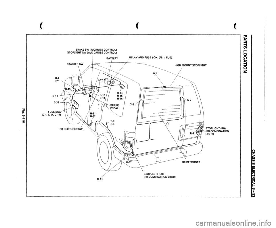
"T1 tO. 00 I _. ... 0>
(
H-7 H-25
,,
B-11
BRAKE
SW
(W/CRUISE
CONTROL)
STOPLIGHT
SW
(W/0
CRUISE
CONTROL) BATTERY
B-38
-
'I ,....., , lUI,).,.
FUSE
sox~
!C-4,
C-14,
C-17l
/
H-44
(
,RELAY
AND
FUSE
BOX
IFL-1,
FL-21
/
~----._
HIGH
MOUNT
STOPLIGHT
~-----
~
G-,~,
~-~------
-~,
I
"~
'
RRDEFOGGER
STOPLIGHT
(LHI
{RR
COMBINATION
LIGHT)
STOPLIGHT
(RHI
(RR
COMBINATION
LIGHT)
(
;g ::xJ ~ r-0 (') ~ -0 2
(') ::t l> en
en en m rm ~ ::Jl ~ Cl) I CD w
Page 1284 of 1928
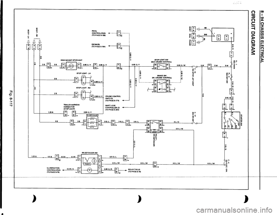
Jl
::!! co (X) I .....
..... ....,
l'l ~ .... J::
.. .. .. .. l'l ~ ~
28 28
STOP LIGHT •
LH
STOP
LIGHT·
RH
TRAILER HARNESS
CONNECTOR
(STOPLIGHT)
RWAL CONTROU.ER(B)
(TO PAGE 8-188)
·-----m:----1
E8CM(25)
(TO
PAGE
8-194)
0.85 G I y I CRUISE CONTROL
UNIT(12) ITO PAGE
8-174)
SHIFT LOCK
CONTROLLER 121
(TO
PAGE
8-202)
0
I
I
1.258
~~~~
r:u
0~~:~------
I
·-
38
1.25
8
0.5 8
0.501L
0.85
GIY :;: 0
I ' IO ... , .. '" ·-
0
•<
~
:
" <
STOPUGHTSW (W/0
CRUISE CONTROL) II
I
I II
8RAKESW
(WI
CRUISE CONTROL) ,, :»m or;;: Ill< o·· " " m ,
I
1-11
0.85GIW 3LIO
'
' •o :m :~ :~
0.5LIW
8
.
ill
-
.. m < .. mm ~ liJ
Ill <::::
-w
I b
[;Jm
I[;Jn ~ § .., :::
5W
"' ~
.. " ..,
II
0.5LIW
•
0.5LIW
11'."1
0.5LIW
I
0.5L/W
b •
Ill -
)
ILLUMINATION CONTROLLER(3) (TO PAGE 8-79)
0.3RIG
RELAY;TAIL(4)
(TO
PAGE 8-78)
)
+ .. .. ,
)
0 -:::0 0 c =i c i> G) :::0 )> s:
00 I CD ""' 0 :I: )> CJ)
CJ) (i) m rm 0 -i :c 0 )> r-
Page 1291 of 1928
STARTER SWITCH
Refer to "START AND CHARGING" in this section.
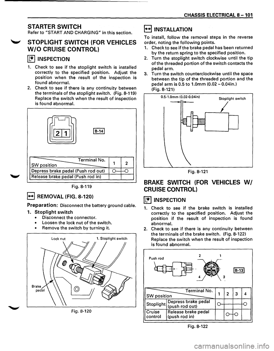
'-' STOPLIGHT SWITCH (FOR VEHICLES
W/0 CRUISE CONTROL)
~ INSPECTION
1. Check to see if the stoplight switch is installed
correctly
to the specified position. Adjust the
position when the result
of the inspection is
found abnormal.
·
2. Check to see if there is any continuity between
the terminals
of the stoplight switch. (Fig. 8-119)
Replace the switch when the result of inspection
is found abnormal.
t[J I B-141
-----==== Terminal No.
SW position
--Depress brake pedal (Push rod out)
Release brake pedal (Push rod in)
Fig. 8-119
B REMOVAL (FIG. 8-120)
1
2
0.: -o
Preparation: Disconnect the battery ground cable.
1. Stoplight switch
• Disconnect the connector.
• Loosen the lock nut of the switch.
• Remove the switch by turning it.
Lock nut 1. Stoplight switch
Fig. 8-120
CHASSIS ELECTRICAL 8-101
B INSTALLATION
To install, follow the removal steps in the reverse
order, noting the
following points.
1. Check to see if the brake pedal has been returned
by the return spring to the specified position.
2. Turn the stoplight switch clockwise until the tip
of the threaded portion of the switch contacts the
pedal arm.
3. Turn the switch counterclockwise until the space
between the
tip of the threaded portion and the
pedal arm is
0.5 to 1.0mm (0.02 -0.04in.)
(Fig. 8-121)
0.5-1.0mm (0.02·0.04in} Stoplight switch
Fig. 8-121
BRAKE SWITCH (FOR VEHICLES WI
CRUISE CONTROL)
~ INSPECTION
1. Check to see if the brake switch is installed
correctly
to the specified position. Adjust the
position
if the result of inspection is found
abnormal.
2. Check to see if there is any continuity between
the terminals
of the brake switch. (Fig. 8-122)
Replace the switch
when the result of inspection
is
found abnormal.
2 1
Pu•h
4 3 -..
~0. SWp 1 2 3 4
Stoplight Depress
brake pedal
(push rod out)
Cruise Release brake pedal
o-f-o control (push rod in)
Fig. 8-122
Page 1362 of 1928
8 -172 CHASSIS ELECTRICAL
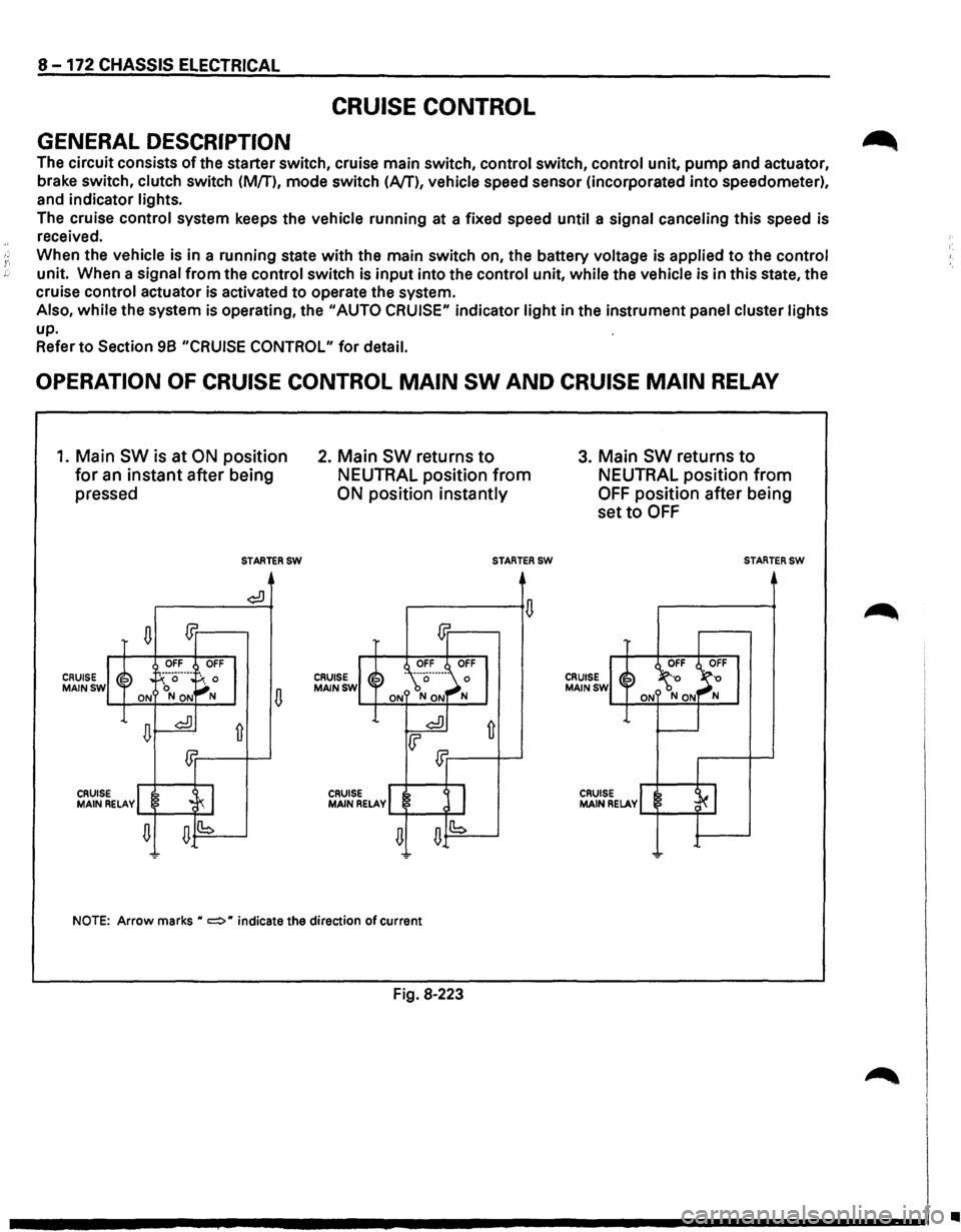
CRUISE CONTROL
GENERAL DESCRIPTION
The circuit consists of the starter switch, cruise main switch, control switch, control unit, pump and actuator,
brake switch, clutch switch (M/T),
mode switch (Nf), vehicle speed sensor (incorporated into speedometer),
and indicator lights.
The cruise
control system keeps the vehicle running at a fixed speed until a signal canceling this speed is
received.
When the vehicle is in a running state with the main switch on, the battery voltage is applied to the control
unit. When a signal from the control switch is input into the control unit, while the vehicle is in this state, the
cruise control actuator is activated
to operate the system.
Also,
while the system is operating, the "AUTO CRUISE" indicator light in the instrument panel cluster lights
up.
Refer
to Section 98 "CRUISE CONTROL" for detail.
OPERATION OF CRUISE CONTROL MAIN SW AND CRUISE MAIN RELAY
1. Main SW is at ON position
for an instant after being
pressed
CRUISE MAINSW
n m
OFF OFF
~~ . !-':··a··---
~: 0 ON NON
n~
£Jr
CRUIS MAIN ~ELAvl .c~ I
n n(b
-
STARTERSW
¢:!)
fi
2. Main SW returns to
NEUTRAL position from
ON position instantly
CRUISE MAINSW
CRUISE MAIN RELAY
STARTERSW
NOTE: Arrow marks H c:::::> H indicate the direction of current
Fig. 8·223
3. Main SW returns to
NEUTRAL position from
OFF position after being
set
to OFF
CRUISE MAINSW
CRUISE MAIN RELAY
STARTERSW
..
Page 1363 of 1928
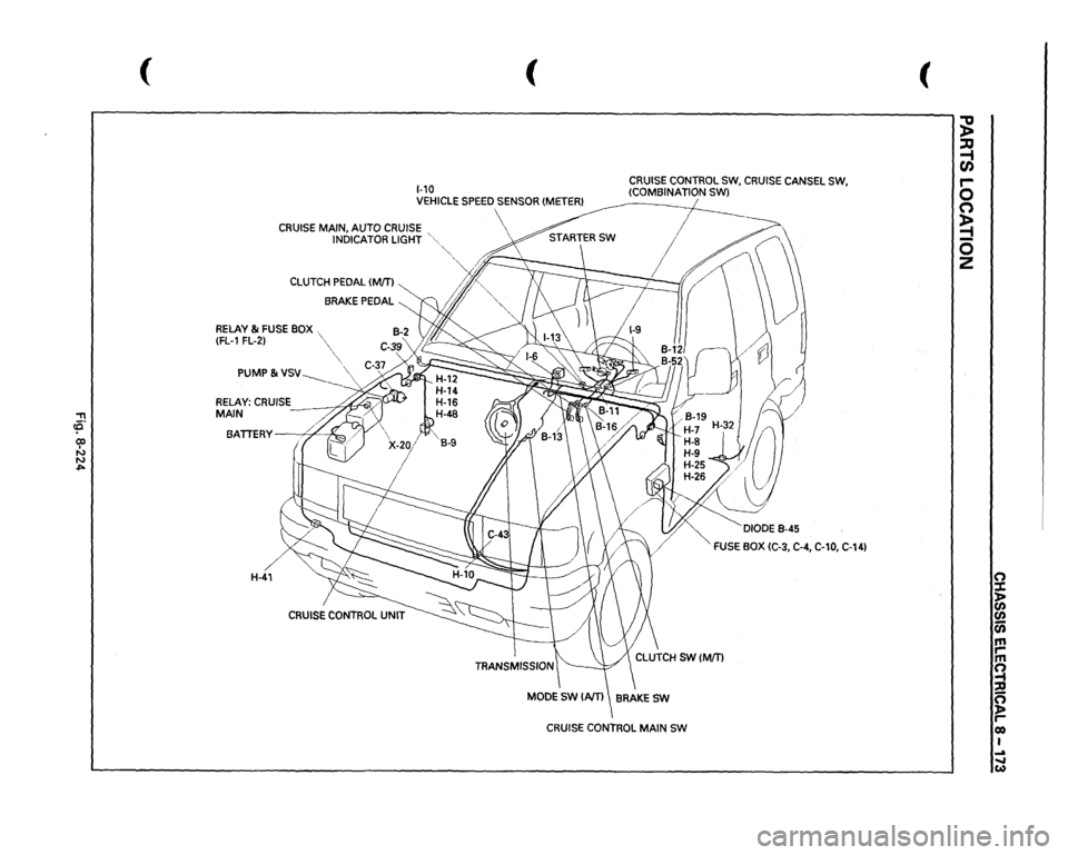
"TI ~· 00 I N N .,..
(
(
1-10 VEHICLE
SPEED
SENSOR
(METER!
CRUISE
CONTROL
SW,
CRUISE
CANSEL
SW,
(COMBINATION SWl
CRUISE
MAIN, AUTO
CRUISE
INDICATOR
LIGHT
'"
CLUTCH
PEDAL
(MfTI
BRAKE
PEDAL
RELAY
& FUSE
BOX
(FL-1
FL-2) PUMP
& VSV-------__
BATTERY
. '/
)",...
H-41
CRUISE
CONTROL
UNIT
·""·
'~~/{' /l/
'
4/
·,,_
DIODE
B-45
FUSE
BOX
(C-3,
C-4,
C-10,
C-14)
CRUISE
CONTROL
MAIN
SW
(
~ ::u ~ r-0 (") ~ 0 z
0 ::t > (/) (/) a; m ,.. m !l ::D 0 )> reo I ... ..... w
Page 1364 of 1928
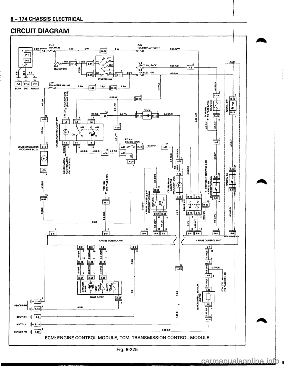
8-174 CHASSIS ELECTRICAL
CIRCUIT DIAGRAM
+ BB/R
B
~
sa
=
=
~~~ BODY ENG. FRAME
CRUISE INDICA TOR !INDICATOR BOX)
{II FENDER-RH II
BODY-RH II
BODY-LH II
FENDER-RH II
&W
C-10
10A ME'IIOR, GAUGE
10
C-1' &W sw 15A STOP, AfT CONT
STAR'IIORSW
38('(
O.&Lm ,-----------'-"--'--1-------1 H-25!------'
0.58
8-8
CRUISE ODNTROL UNIT
0.85 G/W
O.SLNJ
~ "' II! 0
~ :
~ g
ECM: ENGINE CONTROL MODULE, TCM: TRANSMISSION CONTROL MODULE
Fig. 8-225
IM/T) r---r--,
..
"' 1:1 0
;: .. :r ~ 1:> ld I
I
I
I
I
I
I
I
I
I
I
I
I
I
I
~I
I I
I
I
I
I
I
~ I
I .. I 0
12
~ .: u
5
•