lock ISUZU TROOPER 1995 Workshop Manual
[x] Cancel search | Manufacturer: ISUZU, Model Year: 1995, Model line: TROOPER, Model: ISUZU TROOPER 1995Pages: 1928
Page 1809 of 1928
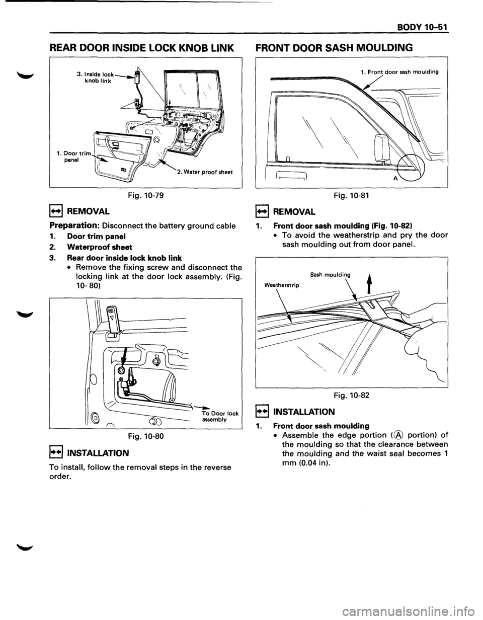
REAR DOOR INSIDE LOCK KNOB LINK
3. Inside lock knob link
1••1 REMOVAL
Fig. 10-79
2. Water proof sheet
Preparation: Disconnect the battery ground cable
1. Door trim panel
2. Waterproof sheet
3. Rear door inside lock knob link
• Remove the fixing screw and disconnect the
locking link at the door lock assembly. (Fig.
10-80)
Fig. 10-80
I••IINSTALLATION
To install, follow the removal steps in the reverse
order.
BODY 10-51
FRONT DOOR SASH MOULDING
'\
r----:1
1. Front door sash moulding
Fig. 10-81
l••l REMOVAL
1. Front door sash moulding (Fig. 10-82)
• To avoid the weatherstrip and pry the door
sash moulding out from door panel.
Sash moulding
Fig. 10-82
I••IINSTALLATION
1. Front door sash moulding
• Assemble the edge portion (@ portion) of
the moulding so that the clearance between
the
moulding and the waist seal becomes 1
mm (0.04 in).
Page 1835 of 1928
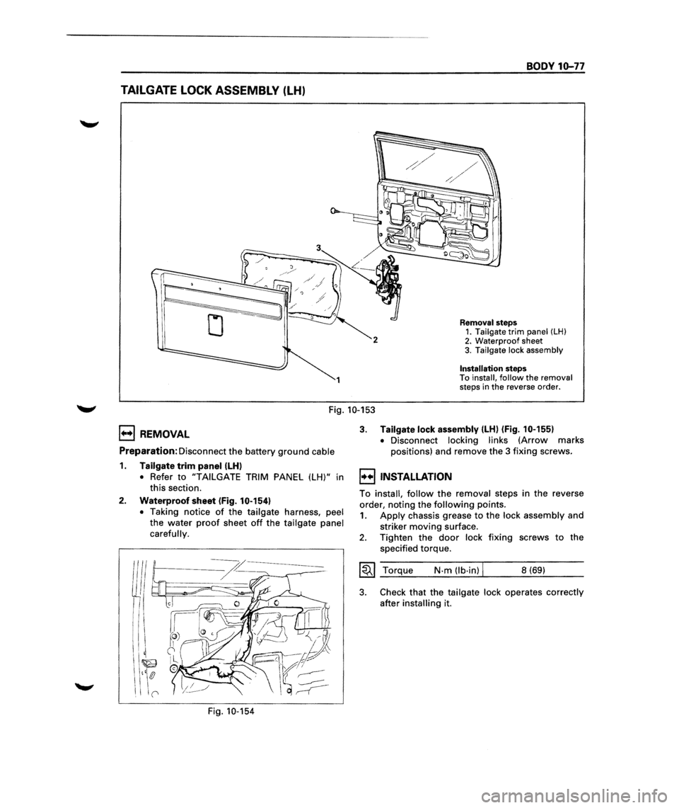
TAILGATE LOCK ASSEMBLY (LH)
1
BODY 10-77
Removal steps 1. Tailgate trim panel (LH) 2. Waterproof sheet
3. Tailgate lock assembly
Installation steps To install, follow the removal
steps in the reverse order.
Fig. 10-153
E) REMOVAL
Preparation: Disconnect the battery ground cable
1. Tailgate trim panel (LH)
• Refer to "TAILGATE TRIM PANEL (LH)" in
this section.
2. Waterproof sheet (Fig. 10-154)
•
Taking notice of the tailgate harness, peel
the water
proof sheet off the tailgate panel
carefully.
Fig. 10-154
3. Tailgate lock assembly {LH) (Fig. 10-155)
•
Disconnect locking links (Arrow marks
positions) and remove the
3 fixing screws.
l••liNSTALLATION
To install, follow the removal steps in the reverse
order, noting the
following points.
1. Apply chassis grease to the lock assembly and
striker
moving surface.
2. Tighten the door lock fixing screws to the
specified torque.
~~~ Torque N·m (lb·in) I 8 (69)
3. Check that the tailgate lock operates correctly
after
installing it.
j
j
j
j
j
j
j
j
j
j
j
j
j
j
j
j
j
j
j
j
j j
j
j
j
j
j
j
j
j
j
j
j
j
j
j
j
j
j
j
j
j
j
j
j j
j
j
j
j
j
j
j
j
j
j
j
j
j
j
j
j
j j
j
j j j
j
j
Page 1836 of 1928
10-78 BODY
To actuator
To inside lock knob I
l
Fig. 10-155
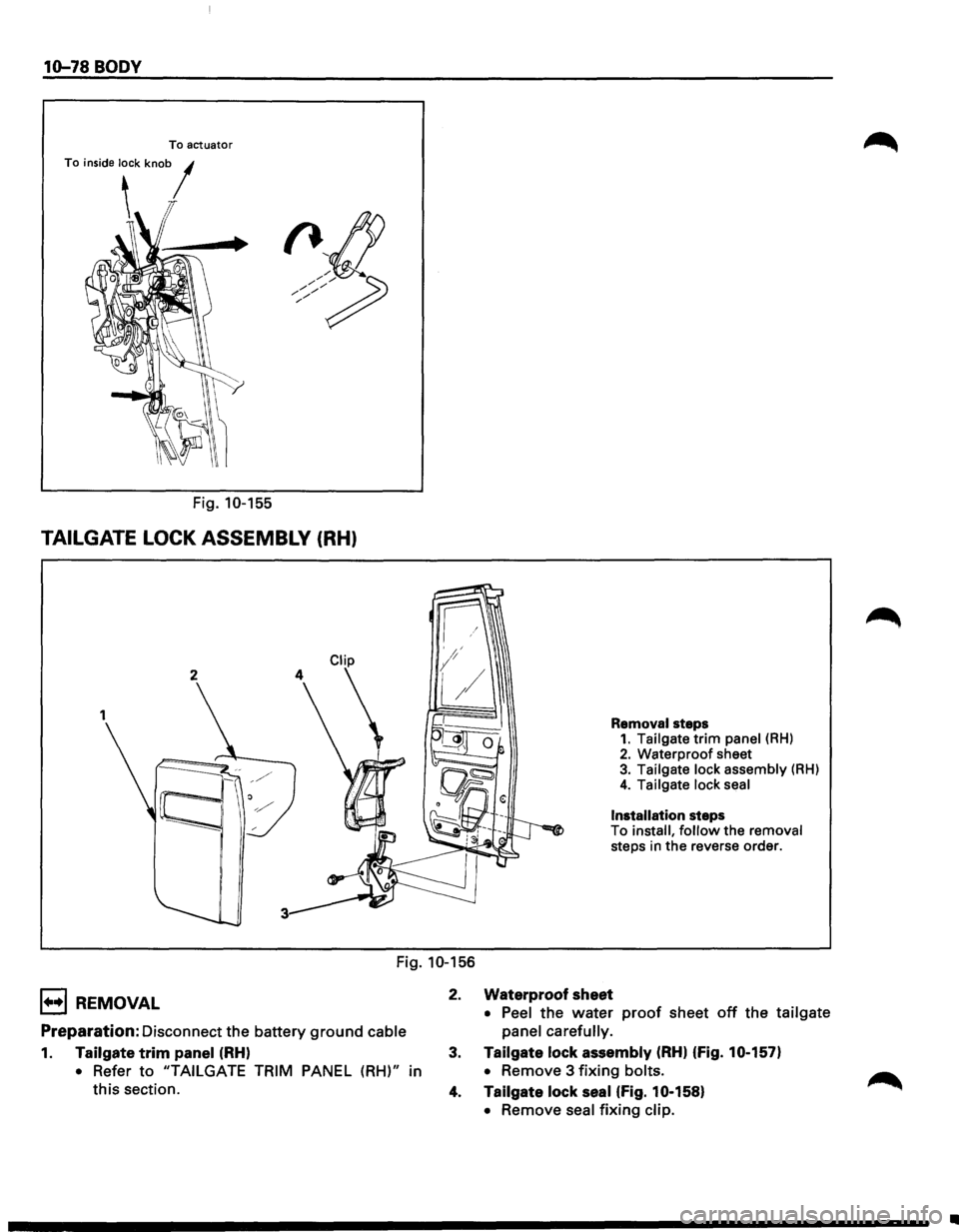
TAILGATE LOCK ASSEMBLY (RH)
2
Removal steps 1. Tailgate trim panel (RH) 2. Waterproof sheet 3. Tailgate lock assembly (RH)
4. Tailgate lock seal
Installation steps
To install, follow the removal
steps in
the reverse order.
Fig. 10-156
1••1 REMOVAL
Preparation: Disconnect the battery ground cable
1. Tailgate trim panel (RH)
• Refer to "TAILGATE TRIM PANEL (RH)" in
this section. 2.
Waterproof sheet
• Peel
the water proof sheet off the tailgate
panel carefully.
3. Tailgate lock assembly (RH) (fig. 10-157)
•
Remove 3 fixing bolts.
4. Tailgate lock seal (fig. 10-158)
•
Remove seal fixing clip.
•
Page 1837 of 1928
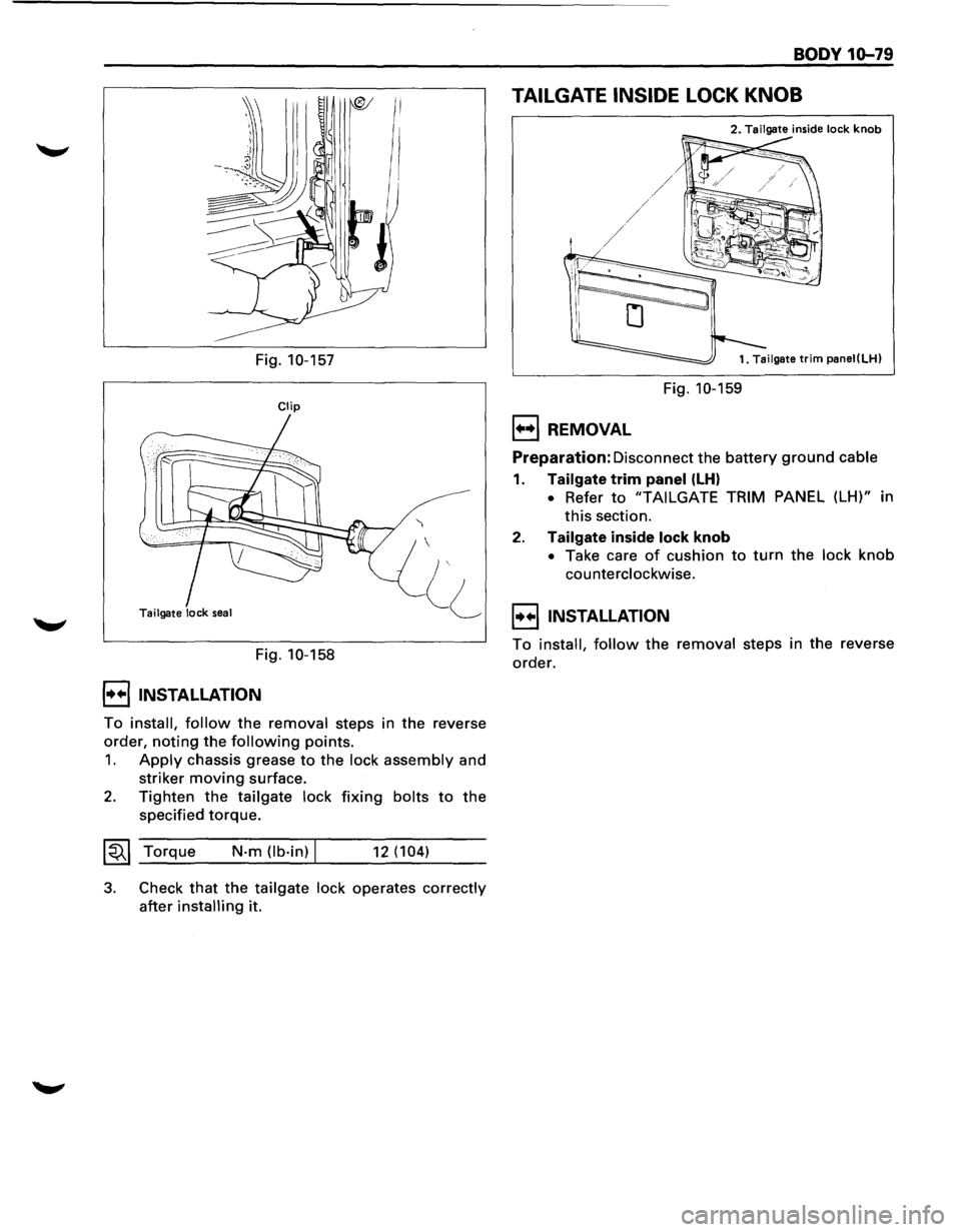
Fig. 10-157
Clip
Tailgate lock seal
Fig. 10-158
I••! INSTALLATION
')
To install, follow the removal steps in the reverse
order,
noting the following points.
1. Apply chassis grease to the lock assembly and
striker
moving surface.
2. Tighten the tailgate lock fixing bolts to the
specified torque.
~~~ Torque N·m (lb·in) I 12 (104)
3. Check that the tailgate lock operates correctly
after installing it.
BODY 10-79
TAILGATE INSIDE LOCK KNOB
2. Tailgate inside lock knob
Fig. 10-159
1•+1 REMOVAL
Preparation: Disconnect the battery ground cable
1. Tailgate trim panel (LH)
• Refer to "TAIL GATE TRIM PANEL (LH)" in
this section.
2. Tailgate inside lock knob
• Take care of cushion to turn the lock knob
counterclockwise.
I••IINSTALLATION
To install, follow the removal steps in the reverse
order.
Page 1838 of 1928
10-80 BODY
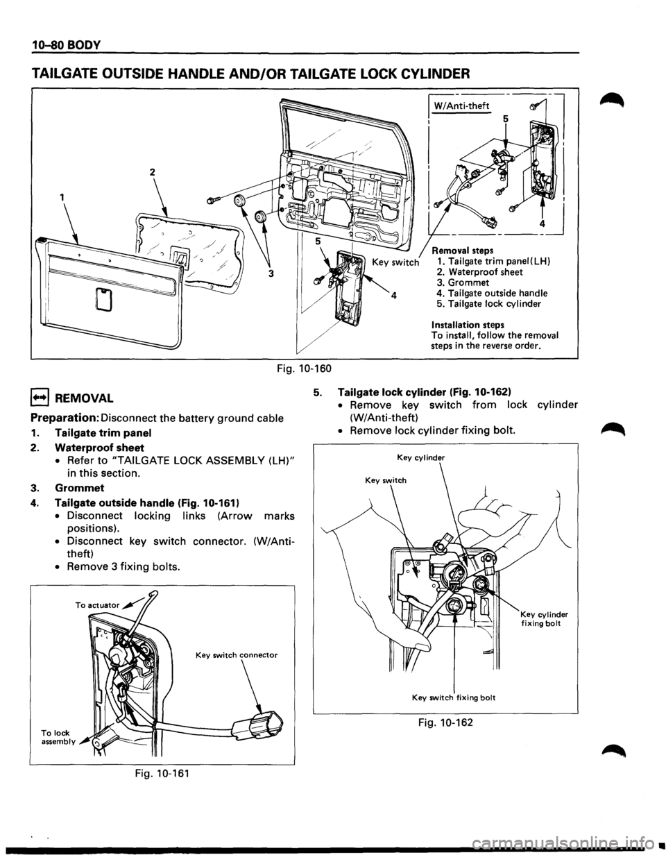
TAILGATE OUTSIDE HANDLE AND/OR TAILGATE LOCK CYLINDER
1
Fig. 10-160
I W/A~ti-theft
I
Removal steps
1. Tailgate trim panei(LH)
2. Waterproof sheet
3. Grommet
4.
Tailgate outside handle 5. Tailgate lock cylinder
Installation steps
To install, follow the removal
steps in the reverse order.
1••1 REMOVAL 5. Tailgate lock cylinder (fig. 10-162)
Preparation: Disconnect the battery ground cable
1. Tailgate trim panel
2. Waterproof sheet
• Refer to "TAILGATE LOCK ASSEMBLY (LH)"
in
this section.
3. Grommet
4. Tailgate outside handle (Fig. 10-161)
•
Disconnect locking links (Arrow marks
positions).
• Disconnect key switch connector. (W/Anti
theft)
• Remove 3 fixing bolts.
To lock assembly
Fig. 10-161
• Remove key switch from lock cylinder
(W/Anti-theft)
• Remove lock cylinder fixing bolt.
Key cylinder
Key switch fixing bolt
Fig. 10-162
Key cylinder fixing bolt
..
Page 1846 of 1928
10-88 BODY
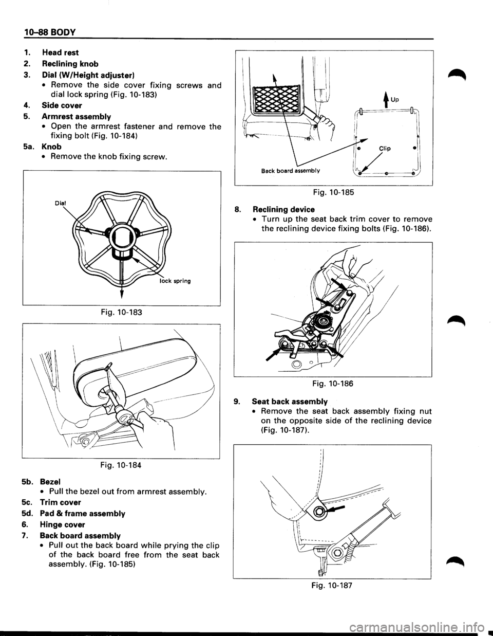
1. Head rest
2.
Reclining knob
3.
Dial (W/Height adjuster)
• Remove the side cover fixing screws and
dial lock spring (Fig. 10-183)
4. Side cover
5. Armrest assembly
• Open
the armrest fastener and remove the
fixing bolt (Fig. 10-184)
Sa. Knob
• Remove the knob fixing screw.
Dial
Fig. 10-183
Fig. 10-184
5b. Bezel
• Pull
the bezel out from armrest assembly.
5c. Trim cover
Sd. Pad & frame assembly
6. Hinge cover
7. Back board assembly
• Pull
out the back board while prying the clip
of the back board free from the seat back
assembly. (Fig. 10-185)
Back board assembly
Fig. 10-185
8. Reclining device
9.
• Turn up the seat back trim cover to remove
the reclining device fixing bolts (Fig. 10-186).
I I
Fig. 10-186
Seat back assembly
•
Remove the seat back assembly fixing nut
on the opposite side of the reclining device
(Fig.
10-187).
Fig. 10-187
Page 1848 of 1928
1o-90 BODY
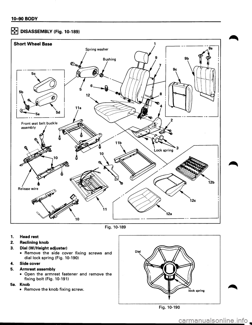
l•!•l DISASSEMBLY (Fig. 10-189)
Short Wheel Base
Spring washer
Front seat belt buckle
assembly
Release
wire
Fig. 10-189
1. Head rest
2.
Reclining knob
3. Dial (W /Height adjuster)
• Remove the side cover fixing screws and
dial lock spring (Fig. 10-190)
4. Side cover
5. Armrest assembly
• Open the armrest fastener and remove the
fixing bolt (Fig. 10-191)
5a. Knob
• Remove the knob fixing screw.
I
________ 1_2a-------~
Fig. 10-190
Page 1854 of 1928
10-96 BODY
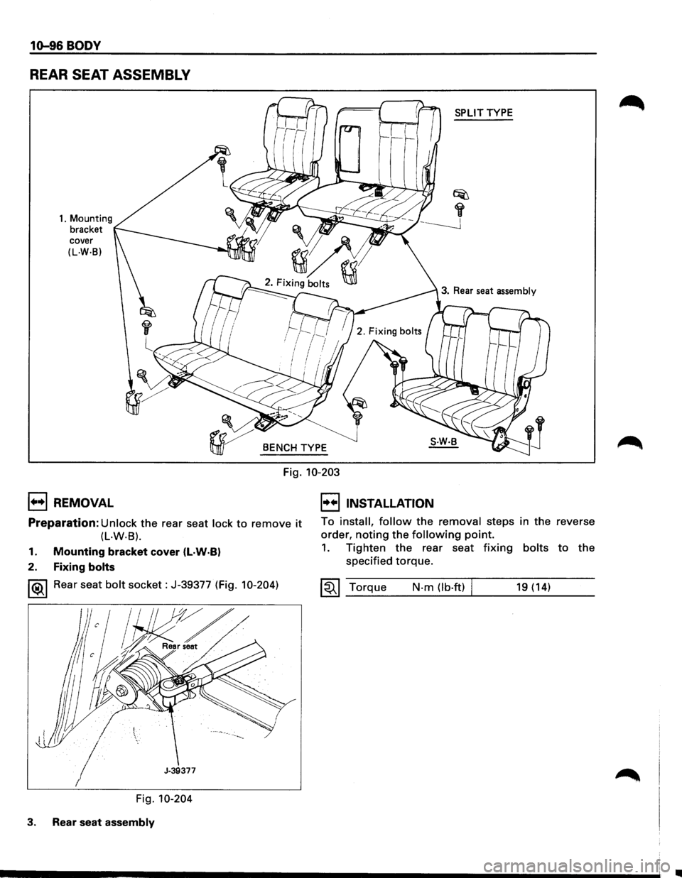
REAR SEAT ASSEMBLY
1. Mounting
bracket
cover
(L.W·B)
1++1 REMOVAL
r
l
SPLIT TYPE
3. Rear seat assembly
BENCH TYPE
Fig. 10-203
I••IINSTALLATION
Preparation: Unlock the rear seat lock to remove it To install, follow the removal steps in the reverse
order, noting the following point. (L·W·B).
1. Mounting bracket cover (l·W·BI
2. Fixing bolts
1®.1 Rear seat bolt socket: J-39377 (Fig. 10-204)
Fig. 10-204
3. Rear seat assembly
1. Tighten the rear seat fixing bolts to the
specified torque.
~~~ Torque N-m (lb-ft) I 19 (14)
..
Page 1855 of 1928
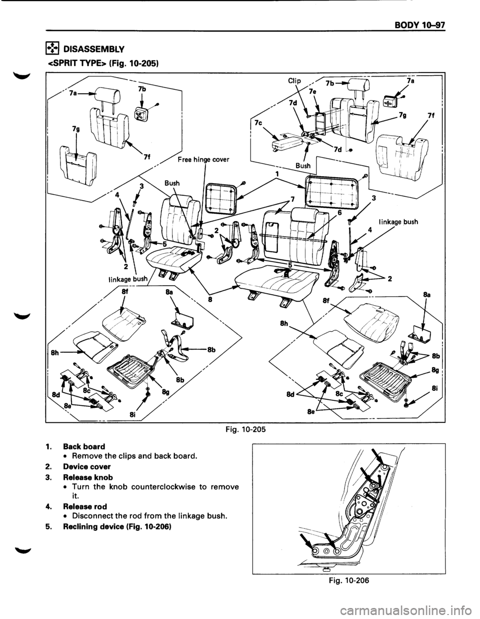
1•!3 DISASSEMBLY
1.
2.
3.
4.
5.
Back board
• Remove the clips and back board.
Device cover
Release knob
Fig. 10-205
•
!urn the knob counterclockwise to remove
lt.
Release rod
• Disconnect the rod from the linkage bush.
Reclining device (Fig. 10-206)
BODY 1G-97
Fig. 10-206
Page 1856 of 1928
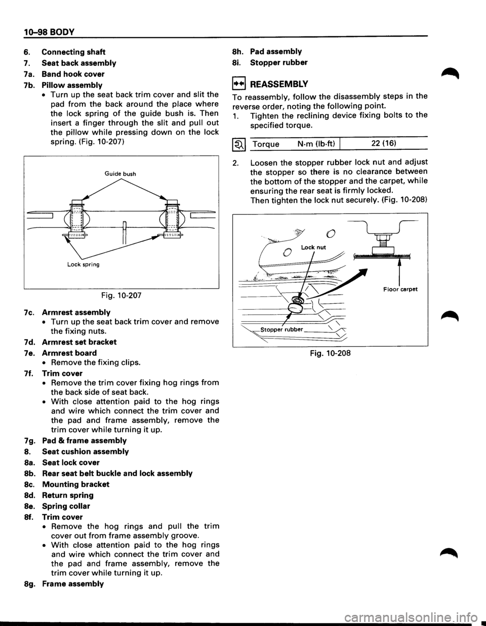
10-98 BODY
6. Connecting shaft
7. Seat back assembly
7a. Band hook cover
7b.
Pillow assembly
•
Turn up the seat back trim cover and slit the
pad
from the back around the place where
the lock spring of the guide bush is. Then
insert a
finger through the slit and pull out
the pillow while pressing down on the lock
spring. (Fig. 10-207)
Guide bush
Lock spring
Fig. 10-207
7c.
Armrest assembly
• Turn up the seat back trim cover and remove
the fixing nuts.
7d.
Armrest set bracket
7e. Armrest board
• Remove the fixing clips.
7f. Trim cover
• Remove the trim cover fixing hog rings from
the back side of seat back.
• With close attention paid to the hog rings
and
wire which connect the trim cover and
the pad and
frame assembly, remove the
trim cover while turning it up.
7g. Pad
& frame assembly
8. Seat cushion assembly
Sa. Seat lock cover
Sb. Rear seat belt buckle and lock assembly
Sc. Mounting bracket
Sd. Return spring
Se. Spring collar
Sf. Trim cover
• Remove the hog rings and pull the trim
cover out from frame assembly groove.
• With close attention paid to the hog rings
and
wire which connect the trim cover and
the pad and frame assembly, remove the
trim cover while turning it up.
Sg. Frame assembly
Sh. Pad assembly
Si. Stopper rubber
1++1 REASSEMBLY
To reassembly, follow the disassembly steps in the
reverse order, noting the following point.
1. Tighten the reclining device fixing bolts to the
specified torque.
~~~ Torque N-m (lb.ft) 22 (16)
2. Loosen the stopper rubber lock nut and adjust
the stopper so there is no clearance between
the bottom of the stopper and the carpet, while
ensuring the rear seat is firmly locked.
Then tighten the lock nut securely. (Fig. 10-208)
0
0
Lock nut
F Iocr carpet
Fig. 10-208