lock ISUZU TROOPER 1995 Workshop Manual
[x] Cancel search | Manufacturer: ISUZU, Model Year: 1995, Model line: TROOPER, Model: ISUZU TROOPER 1995Pages: 1928
Page 1582 of 1928
9A-6 RADIO
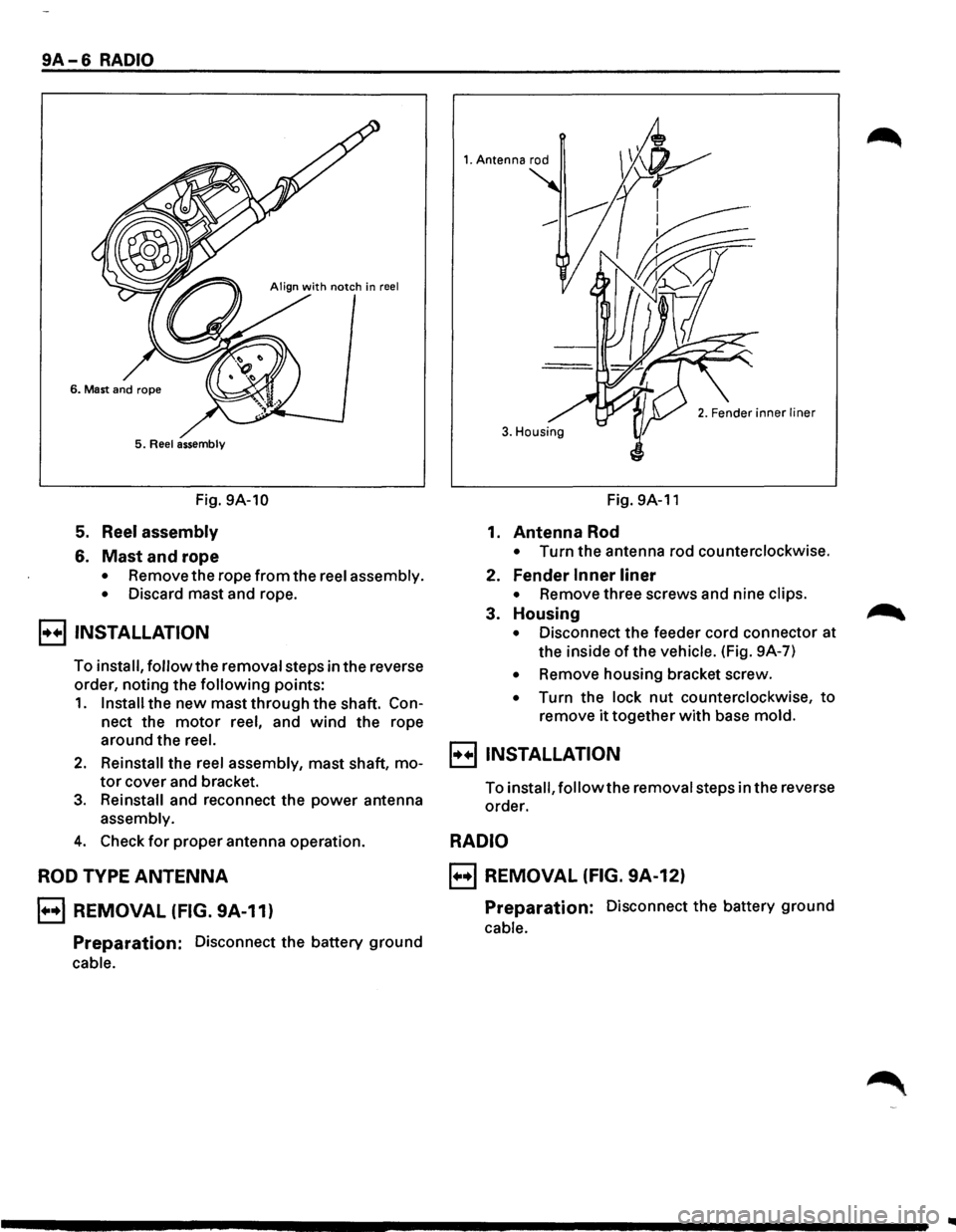
5. Reel assembly
Fig. 9A-10
5. Reel assembly
6. Mast and rope
• Remove the rope from the reel assembly.
•
Discard mast and rope.
B INSTALLATION
To install, follow the removal steps in the reverse
order, noting the
following points:
1. Install the new mast through the shaft. Con
nect the motor reel, and wind the rope
around the
reel.
2. Reinstall the reel assembly, mast shaft, mo
tor cover and bracket.
3. Reinstall and reconnect the power antenna
assembly.
4. Check for proper antenna operation.
ROD TYPE ANTENNA
B REMOVAL (FIG. 9A-11)
Preparation: Disconnect the battery ground
cable.
1. Antenna rod
3. Housing
Fig. 9A-11
1. Antenna Rod
• Turn the antenna rod counterclockwise.
2. Fender Inner liner
• Remove three screws and nine clips.
3. Housing
• Disconnect the feeder cord connector at
the inside
of the vehicle. (Fig. 9A-7)
• Remove housing bracket screw.
• Turn the lock nut counterclockwise, to
remove it together with base mold.
B INSTALLATION
To install, follow the removal steps in the reverse
order.
RADIO
B REMOVAL (FIG. 9A-12)
Preparation: Disconnect the battery ground
cable.
Page 1583 of 1928
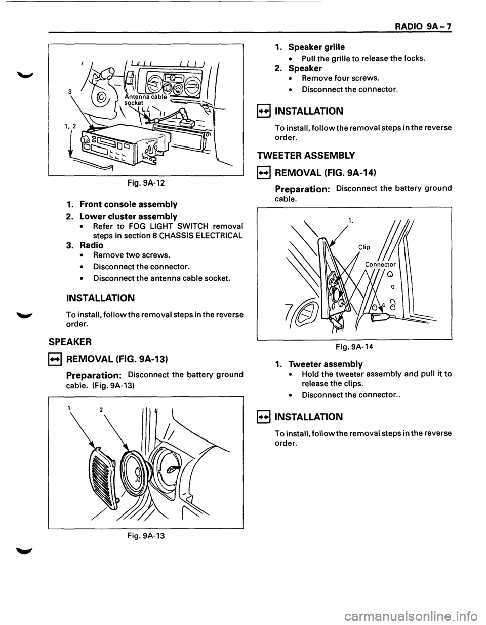
Fig. 9A-12
1. Front console assembly
2. Lower cluster assembly
• Refer to FOG LIGHT SWITCH removal
steps in section 8 CHASSIS ELECTRICAL
3. Radio
• Remove two screws.
• Disconnect the connector.
• Disconnect the antenna cable socket.
INSTALLATION
To install, follow the removal steps in the reverse
order.
SPEAKER
B REMOVAL (FIG. 9A-13)
Preparation: Disconnect the battery ground
cable. (Fig. 9A-13)
Fig. 9A-13
RADIO 9A-7
1. Speaker grille
• Pull the grille to release the locks.
2. Speaker
• Remove four screws.
• Disconnect the connector.
8 INSTALLATION
To install, followthe removal steps in the reverse
order.
TWEETER ASSEMBLY
B REMOVAL (FIG. 9A-14)
Preparation: Disconnect the battery ground
cable.
l. CUp j
Connector
0
Fig. 9A-14
1. Tweeter assembly
• Hold the tweeter assembly and pull it to
release the clips.
•
Disconnect the connector ..
8 INSTALLATION
To install, followthe removal steps in the reverse
order.
Page 1612 of 1928
98-28 CRUISE CONTROL
ON-VEHICLE SERVICE
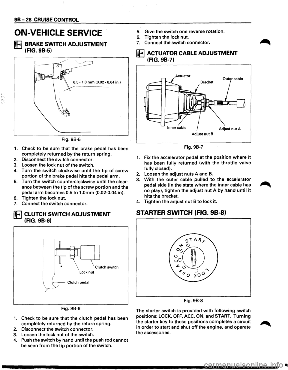
IE BRAKE SWITCH ADJUSTMENT
(FIG. 9B-5)
0.5 -1.0 mm (0.02 -0.04 in.}
Fig. 98-5
1. Check to be sure that the brake pedal has been
completely returned by the return spring.
2. Disconnect the switch connector.
3. Loosen the lock nut of the switch.
4. Turn the switch clockwise until the tip of screw
portion of the brake pedal hits the pedal arm.
5. Turn the switch counterclockwise until the clear
ance between the
tip of the screw portion and the
pedal arm becomes 0.5
to 1.0mm (0.02-0.04 in).
6. Tighten the lock nut.
7. Connect the switch connector.
IE CLUTCH SWITCH ADJUSTMENT
(FIG. 9B-6)
Clutch switch
--Clutch pedal
Fig. 98-6
1. Check to be sure that the clutch pedal has been
completely returned by
the return spring.
2. Disconnect the switch connector.
3. Loosen the lock nut of the switch.
4. Push the switch by hand until the push rod cannot
be seen from the tip portion of the switch.
5. Give the switch one reverse rotation.
6. Tighten the lock nut.
7. Connect the switch connector.
IE ACTUATOR CABLE ADJUSTMENT
(FIG. 9B-7)
Actuator
Adjust nut A
Adjust nut B
Fig. 98-7
1. Fix the accelerator pedal at the position where it
has been fully returned (with the throttle valve
fully closed).
2. Loosen the adjust nuts A and B.
3. With the outer cable pulled to the accelerator
pedal side (in the state
where the inner cable has
no play),
tighten the adjust nut A by hand until it
hits the bracket.
4. Tighten the adjust nut 8 to lock it.
STARTER SWITCH (FIG. 98-8)
Fig. 98-8
The starter switch is provided
with following switch
positions:
LOCK, OFF, ACC, ON, and START. Turning
the starter key to these positions completes a circuit
in
order to start and shut off the engine, and operate
the accessories.
Page 1613 of 1928
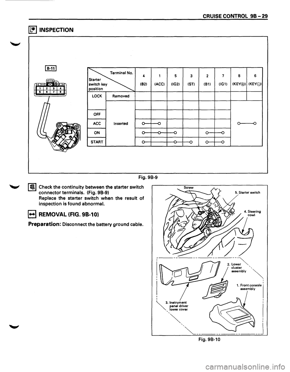
~ INSPECTION
I B-111
~
4 1
(82)
IACCI
LOCK Removed
OFF
ACC Inserted
ON -
START
Fig. 98-9
I t!l Check the continuity between the starter switch
connector
terminals. (fig. 98-9)
Replace the starter switch when the result of
inspection is found abnormal.
B REMOVAL (FIG. 98-10)
Preparation: Disconnect the battery ground cable.
5 3
IIG2) 1ST)
CRUISE CONTROL 98-29
2 7
(81) IIG1)
Fig. 98-10
8 6
IKEY(j;)) IKEY81
o----o
5. Starter switch
I
I
1. Front console I assembly
Page 1615 of 1928
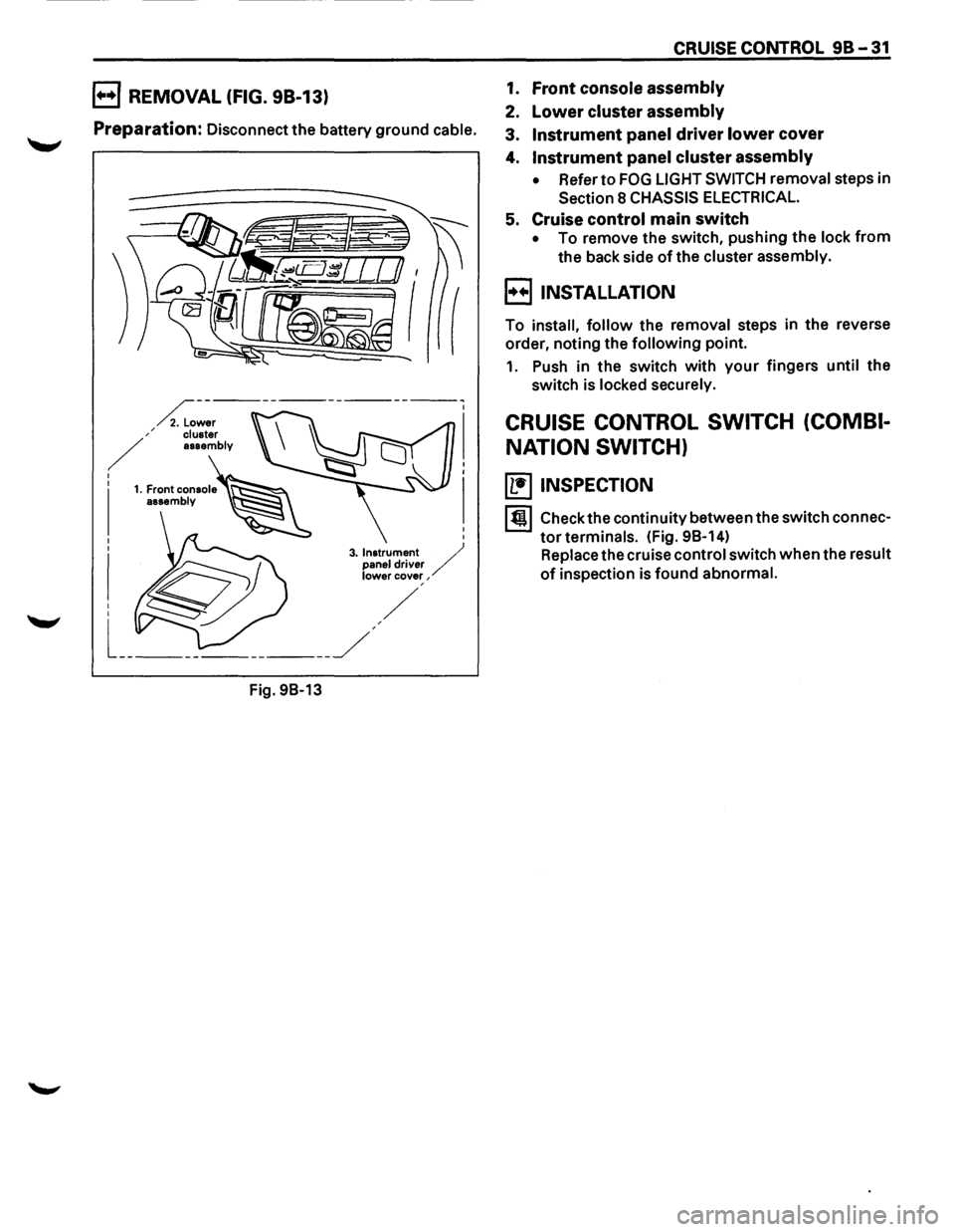
B REMOVAL (FIG. 98-13)
Preparation: Disconnect the battery ground cable.
Fig.
98-13
CRUISE CONTROL 98-31
1. Front console assembly
2. Lower cluster assembly
3. Instrument panel driver lower cover
4. Instrument panel cluster assembly
• Refer to FOG LIGHT SWITCH removal steps in
Section 8 CHASSIS ELECTRICAL.
5. Cruise control main switch
• To remove the switch, pushing the lock from
the back side of the cluster assembly.
B INSTALLATION
To install, follow the removal steps in the reverse
order, noting the
following point.
1. Push in the switch with your fingers until the
switch is locked securely.
CRUISE CONTROL SWITCH (COMBI
NATION SWITCH)
(b!] INSPECTION
I till Check the continuity between the switch connec
tor terminals. (Fig. 98-14)
Replace the cruise control switch when the result
of inspection is found abnormal.
Page 1623 of 1928
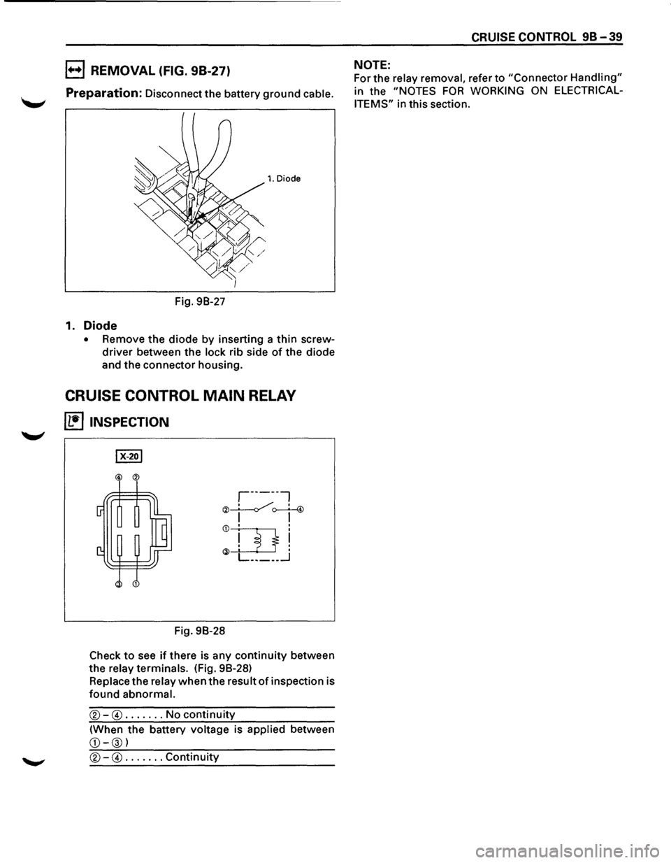
B REMOVAL (FIG. 98-27)
Preparation: Disconnect the battery ground cable.
1. Diode
Fig. 98-27
1. Diode
• Remove the diode by inserting a thin screw
driver between the lock rib side of the diode
and the connector housing.
CRUISE CONTROL MAIN RELAY
~ INSPECTION
@ ®
,-----,
®~~ I I
Q)~!
~J___l___J . L _____ _j
Fig. 98-28
Check
to see if there is any continuity between
the
relay terminals. (Fig. 98-28)
Replace the relay when the result of inspection is
found abnormal.
®-@ ....... No continuity
(When the battery voltage is applied between
CD-®l
®-@ ....... Continuity
CRUISE CONTROL 98-39
NOTE:
For the relay removal, refer to "Connector Handling"
in the "NOTES FOR WORKING ON ELECTRICAL
ITEMS"
in this section.
Page 1625 of 1928
Supplemental Restraint System 9J-1
SECTION 9J
SUPPLEMENTAL RESTRAINT SYSTEM
(SRS)
WARNING: THIS VEHICLE IS EQUIPPED WITH A SUPPLEMENTAL INFLATABLE RESTRAINT SYSTEM (SRS).
REFER TO WARNING IN THIS SECTION UNDER "ON-VEHICLE SERVICE" AND THE SRS COMPONENT AND
WIRING LOCATION VIEW IN THIS SECTION BEFORE PERFORMING SERVICE ON OR AROUND SRS
COMPONENTS OR WIRING. FAILURE TO FOLLOW WARNING COULD RESULT IN POSSIBLE AIR BAG
DEPLOYMENT, PERSONAL INJURY, OR OTHERWISE UNNEEDED SRS REPAIRS.
TABLE OF CONTENTS
SUPPLEMENTAL RESTRAINT SYSTEM
(SRS)
SECTION 1 -INTRODUCTION
CAUTION: WHEN FASTENERS ARE REMOVED, ALWAYS REINSTALL THEM AT THE SAME LOCATION
FROM WHICH THEY WERE REMOVED. IF A FASTENER NEEDS TO BE REPLACED, USE THE CORRECT PART
NUMBER FASTENER FOR THAT APPLICATION. IF THE CORRECT PART NUMBER FASTENER IS NOT
AVAILABLE, A FASTENER OF EQUAL SIZE AND STRENGTH (OR STRONGER) MAY BE USED. FASTENERS
THAT ARE NOT REUSED, AND THOSE REQUIRING THREAD LOCKING COMPOUND WILL BE CALLED OUT.
THE CORRECT TORQUE VALUE MUST BE USED WHEN INSTALLING FASTENERS THAT REQUIRE IT. IF THE
ABOVE CONDITIONS ARE NOT FOLLOWED, PARTS OR SYSTEM DAMAGE COULD RESULT.
GENERAL DESCRIPTION • • • . • . . . . • . . . . . . . . . • . . . . • . . . . . . . . • . . . . . . . . • . . . . • . • . . 3
Restraint Devices • • • • • • • • • • • • • • • • • • • • • • • • • • .. • • • • • • • • • • • • • • • • • • • • • • • • • • • • • • • • 3
'W' System Description • • • • • • • • • • • • • • • • • • • • • • • • • • • • • • • • • • • • • • • • • • • • • • • • • • • • • • • • • • 4
SRS Component and wiring Location View . . . . . . • . . . . . . . . . . . • . . . . • . . . . . . . . . . • • 5
COMPONENT DESCRIPTION • • . .
. .
• . . • . .
.
• . . • . . . . . . . . . . . . . . . . . • . • . • . . . . • . • • . . 6
DERM ••••••••••••••••••\
••••••••••••••••••\
••••••••••••••••••\
•••••••• ~ • • • • • 6
"AIR BAG"Warnlng Lamp • • • • • • • • • • • • • • • • • • • • • • • • • • • • • • • • • • • • • • • • .. • • • • • • • • • • • • 6
Dual Pole Arming Sensor • • • • • • • • • • • • • • • • • • • • • • • • • • • • • • • • • • • • • • • • • • • • • • • • • • • • • 6
Discriminating Sensors • • • • • • • • • • • • • • • • • • • • • • • • • • • • • • • • • • • • • • • • • • • • • • • • • • • • • • • 6
SRS Coli Assembly • • • • • • • • • • • • • • • • • • • • • • • • • • • • • • • • • • • • • • • • • • • • • • • • • • • • • • • • • • 7
Inflator Modules • • • • • • • • • • • • • • • • • • • • • • • • • • • • • • • • • • • • • • • • • • • • • • • • • • • • • • • • • • • • 7
Steering Column • • • • • • • • • • • • • • • • • • • • • • • • • • • • • • • • • • • • • • • • • • • • • • • • • • • • • • • • • • • • 7
Knee Bolster • • • • • • • • • • • • • • • • • • • • • • • • • • • • • • • • • • • • • • • • • • • • • • • • • • • • • • • • • • • • • • • 7
DEFINITIONS • • . • . . • • • . • • . • • • • • . • . . • • . • . . . . . . . . . . . . . . . . . . . . . . . . . . . • . . . • • • • • • 8
DIAGNOSIS • • • • • • • • • • • • • • • • • • • • • • • • • • • . • • • • • • . • • • • • . . • • . . . . • • • • • . • • • • • • • • • • • 1 0
Diagnostic Trouble Codes • • • • • • • • • • • • • • • • • • • • • • • • • • • • • • • • • • • • • • • • • • • • • • • • • • • • • 1 0
Scan Tool Diagnostic • • • • • • • • • • • • • • • • • • • • • • • • • • • • • • • • • • • • • • • • • • • • • • • • • • • • • • • • 1 0
Use of Special Tools • • • • • • • • • • • • • • • • • • • • • • • • • • • • • • • • • • • • • • • • • • • • • • • • • • • • • • • • • 1 0
SRS CONNECTOR BODY FACE VIEWS . . . . . . . . . . . • . . . . . . . . . . . . . . . . . . . . . • . . . . . 11
REPAIRS AND INSPECTION REQUIRED AFTER AN ACCIDENT . . . . . • . . . . . . . . . . . 12
Accident With Deployment-component Replacement and Inspections • • • • • • • • • • • • • • • • • • 12
Accident With or Without Deployment-Component Inspections • • • • • • • • • • • • • • • • • • • • • • • 12
Sensor Replacement Guideline ••••••••• II • • • • • • • • • • • • • • • • • • • • • • • • • • • • • • • • • • • • • • • 12
Wiring Damage ••••••••••••••••••\
••• II • • • • • • • • • • • • • • • • • • • • • • • • • • • • • • • • • • • • • • • 12
SRS Conector (Plastic Body and Terminal Metal Pin) Damage • • • • • • • • • • • • • • • • • • • • • • • • • 12
Page 1637 of 1928
Supplemental Restraint System 9J-13
ON-VEHICLE SERVICE
SERVICE PRECAUTIONS
WARNING: WHEN PERFORMING SERVICE ON OR
AROUND SRS COMPONENTS OR SRS WIRING,
FOLLOW
THE PROCEDURES LISTED BELOW TO
TEMPORARILY DISABLE THE SRS. FAILURE TO
FOLLOW PROCEDURES COULD RESULT IN
POSSIBLE AIR
BAG DEPLOYMENT, PERSONAL
INJURY OR OTHERWISE
UNNEEDED SRS
REPAIRS.
The DERM in Driver-Passenger SRS can maintain
sufficient voltage to cause a deployment for up to 2
minutes after the ignition switch is turned
"OFF," the
battery is disconnected, or the fuse powering the DERM
is removed.
Many of the service procedures require removal of the
"AIR BAG" fuse, and disconnection of the inflator
modules from the deployment loop to avoid an accidental
deployment.
If the inflator module is disconnected from
the deployment loop as noted in the "Disabling the
SRS"
procedure that follows, service can begin immediately
without waiting for the 2-minute time period to expire.
DISABLING THE SRS
REMOVAL
Turn the ignition switch to "OFF"
1. Remove SRS fuse C-21, C-22, C-23 and C-24 from
left dash side lower fuse block.
2. Disconnect yellow 3-way connector at the base of
steering column.
3. Remove 1/P compartment door assembly, Refer to
"Passenger inflator module replacement" in section
9J-132.
4. Disconnect yellow 4-way connector behind the 1/P
compartment door assembly.
IMPORTANT
• With the "AIR BAG" fuse removed and ignition switch
"ON," if Fuse 21 left. the "AIR BAG" warning lamp will
be "ON." This is normal operation and does not
indicate an
SRS malfunction.
ENABLING THE SRS
INSTALLATION
Turn ignition switch to "LOCK" and remove key.
1. Connect yellow 4-way connector for passenger
inflator module.
2. 1/P compartment door assembly, Refer to
"Passenger inflator module replacemenf' in section
9J-3.
3. Connect yellow 2-way connector at the base of the
steering column.
4. Install "AIR BAG" fuse C-21, C-22, C-23 and C-24 to
left dash side lower fuse block.
Turn ignition switch to
"RUN" and verify that the "AIR
BAG"
warning lamp flashes seven times and then turns
"OFP' If it does not operate as described, perform the
"SRS Diagnostic System Check" in section 9J-2.
HANDLING/INSTALLATION/DIAGNOSIS
1. Inflator modules should not be subjected to
temperatures above
65°C{150°F).
2. Discriminating sensors, inflator modules, arming
sensors, or DERMs should not be used if they have
been dropped from a height
of 91.4 centimeters
{3feet).
3. When a discriminating sensor or arming sensor is
replaced, it must be oriented with the arrow on the
sensor pointing toward the front of the vehicle.
It is
very important for the discriminating sensors and
arming sensor to be located flat on the mounting
surface, parallel to the vehicle datum line.
It is
important that the sensor mounting surface is free of
any dirt or other foreign material.
4. Do not apply power to the SRS unless all
components are connected or a diagnostic chart
requests it, as this
will set a diagnostic trouble code.
5. The "SRS Diagnostic System Check" must be the
starting point of any
SRS diagnostics. The "SRS
Diagnostic System Check" will verify proper "AIR
BAG"
warning lamp operation and will lead you to the
correct chart to diagnose any
SRS malfunctions.
Bypassing these procedures may result
in extended
diagnostic time, incorrect diagnosis, and incorrect
parts replacements.
Page 1640 of 1928
9J-16 Supplemental Restraint ~
DEPLOYMENT OUTSIDE VEHICLE (DRIVER
INFLATOR
MODULE)
Deployment outside the vehicle is proper when the
vehicle is to be returned to service. This includes, for
example, situations in which the vehicle will be returned
to
useful service after a functionally or cosmetically
deficient
inflator module is replaced. Deployment and
disposal of a malfunctioning inflator module is, of course,
subject to any required retention period.
For deployment of a
live (undeployed) inflator module
outside the vehicle, the deployment procedure must be
followed exactly. Always wear safety glasses during this
deployment procedure
until a deployed inflator module is
scrapped
or until an undeployed inflator module is
shipped. Before performing the procedures, you
should
be familiar with servicing the SRS and with proper
handling of the inflator module. Procedures should be
read fully before they are performed.
The following procedure requires use of J-41434
SRS
deployment harness with appropriate pigtail adapter. Do
not attempt procedure without J-41434 adapter.
WARNING: FAILURE TO FOLLOW PROCEDURES
IN
THE ORDER LISTED MAY RESULT IN PERSONAL
INJURY.
NEVER CONNECT DEPLOYMENT
HARNESS TO ANY POWER SOURCE BEFORE
CONNECTING DEPLOYMENT HARNESS TO THE
DRIVER INFLATOR MODULE. DEPLOYMENT
HARNESS SHALL REMAIN SHORTED AND NOT BE ~
CONNECTED TO A POWER SOURCE UNTIL THE
AIR BAG IS TO BE DEPLOYED. THE INFLATOR
MODULE WILL IMMEDIATELY DEPLOY THE AIR
BAG WHEN A POWER SOURCE IS CONNECTED TO
IT. WEAR SAFETY GLASSES THROUGHOUT THIS
ENTIRE DEPLOYMENT AND DISPOSAL
PROCEDURE.
NOTE
• This information applies only to driver inflator
modules. Refer to "Deployment Outside
Vehicle(Passenger Inflator Module)" in this section
for information on passenger inflator module
scrapping.
1. Turn ignition switch to "LOCK," remove key and put
on safety glasses.
2. Inspect J-41434 SRS Deployment Harness and
appropriate
pigtail adapter for damage. If harness or
pigtail adapter is damaged, discard and obtain a
replacement.
•
Page 1643 of 1928
~ Supplemental Restraint System 9J-19
26. Temporarily store the driver inflator module with its inflator module can be found in the applicable service
vinyl trim cover facing
up, away from the surface manual or in a service bulletin.
upon which is rests.
27.
Call the Technical Assistance group for further
assistance.
DEPLOYMENT OUTSIDE VEHICLE
(PASSENGER INFLATOR MODULE)
WARNING: FAILURE TO FOLLOW PROPER SRS
INFLATOR MODULE DISPOSAL PROCEDURES
CAN RESULT IN AIR BAG DEPLOYMENT WHICH
MAY CAUSE PERSONAL INJURY. UNDEPLOYED
INFLATOR MODULES MUST NOT BE DISPOSED OF
THROUGH NORMAL REFUSE CHANNELS. THE
UNDEPLOYED INFLATOR MODULE CONTAINS
SUBSTANCES
THAT CAN CAUSE SEVERE ILLNESS
OR
PERSONAL INJURY IF THE SEALED
CONTAINER IS DAMAGED DURING DISPOSAL.
DISPOSAL
IN ANY MANNER INCONSISTENT WITH
PROPER PROCEDURES MAY BE A VIOLATION OF
FEDERAL, STATE AND/OR LOCALLAWS.
Deployment out of the vehicle is proper when the vehicle
is to be returned to service. This includes, for example,
situations
in which a functionally or cosmetically deficient
inflator module
is replaced. Deployment and disposal of
an inflator module is, of course, subject to any required
reterntion period.
For deployment
of a live inflator module out of the
·'-" vehicle, the deployment procedure must be followed
exactly.
ALWAYS wear safety glasses during this
deployment procedure until the deployed inflator module
is scrapped. Before performing the procedures you
should
be familiar with servicing the SRS system and
with proper handling of the inflator module. Procedures
should be read fully before they are performed.
The following procedure requires use of J-41434
SIR
Deployment Harness with the appropriate pigtail
adapter. The procedure also requires the use of J-41497
Passenger
Side SRS Module Deployment Fixture. Do
not attempt this procedure without J-41434 and adapter,
and J-41497.
WARNING: FAILURE TO FOLLOW PROCEDURES
IN THE ORDER LISTED MAY RESULT IN PERSONAL
INJURY.
NEVER CONNECT DEPLOYMENT
HARNESS TO ANY POWER SOURCE BEFORE
CONNECTING DEPLOYMENT HARNESS TO THE
INFLATOR MODULE. DEPLOYMENT HARNESS
SHALL REMAIN SHORTED AND NOT BE
CONNECTED TO A POWER SOURCE UNTIL THE
AIRBAG IS TO BE DEPLOYED. THE INFLATOR
MODULE WILL IMMEDIATELY DEPLOY THE
AIRBAG WHEN A POWER SOURCE IS CONNECTED
TO IT. WEAR SAFETY GLASSES THROUGHOUT
THIS ENTIRE DEPLOYMENT AND DISPOSAL
~ PROCEDURE.
NOTE: This information applies only to passenger
inflator modules. Information for disposing of a live driver
1. Turn ignition switch to "LOCK", remove key, and put
on safety glasses.
2. Inspect J-41434 SRS Deployment Harness and
appropriate pigtail adapter for damage.
If harness or
pigtail is damaged, discard and obtain a
replacement.