lock ISUZU TROOPER 1995 Workshop Manual
[x] Cancel search | Manufacturer: ISUZU, Model Year: 1995, Model line: TROOPER, Model: ISUZU TROOPER 1995Pages: 1928
Page 1468 of 1928
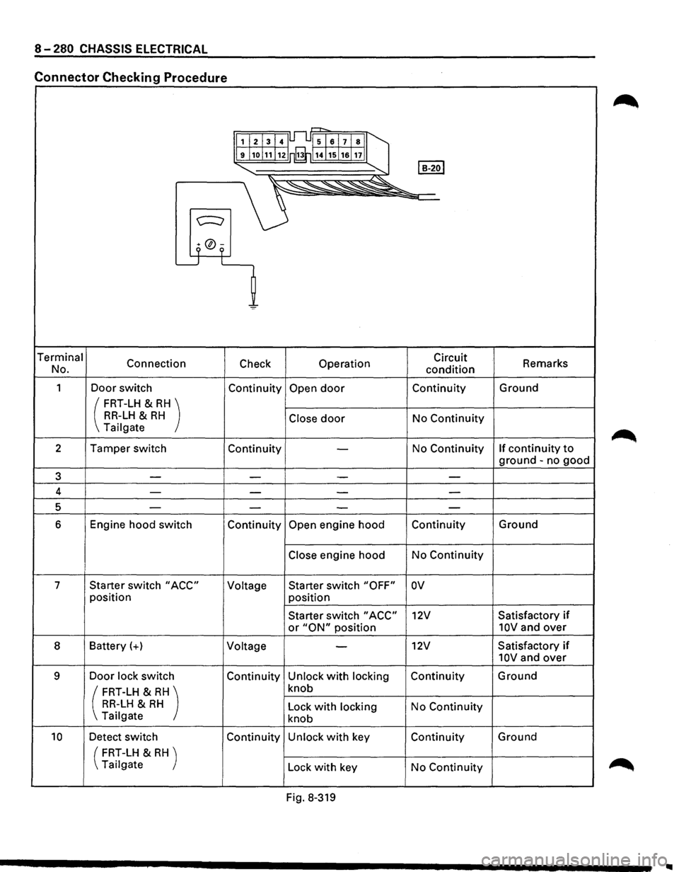
8-280 CHASSIS ELECTRICAL
Connector Checking Procedure
r=-r-,
1I213141Jl..l51al7lsll
9j1ol11!12 rfi114j15j1alnll
I B-2ol "-... ~
~~"'--~~"
c:::::::;
9 °9 L_j L
=
Terminal
Connection Check Operation Circuit
Remarks
No.
condition
1 Door switch Continuity Open door Continuity Ground
( FRT-LH & RH) RR-LH & RH Close door No Continuity Tailgate
2 Tamper switch
Continuity
-No Continuity If continuity to
ground -no good
3 -
-I - -
4 ---
-
5 ----
6 Engine hood switch Continuity Open engine hood Continuity Ground
Close engine hood
No Continuity
7 Starter switch
"ACC" Voltage Starter
switch "OFF" ov
position
position
Starter switch
"ACC" 12V Satisfactory if
or "ON" position 10V and over
8 Battery(+)
Voltage -12V Satisfactory if
10V and over
9 Door lock switch Continuity Unlock with locking Continuity Ground
( FRT-LH & RH) knob
RR-LH & RH Lock with locking No Continuity
Tailgate knob
10 Detect switch Continuity Unlock with key Continuity Ground
(
FRT-LH & RH )
Tailgate Lock
with key No Continuity
Fig. 8-319
..
Page 1469 of 1928
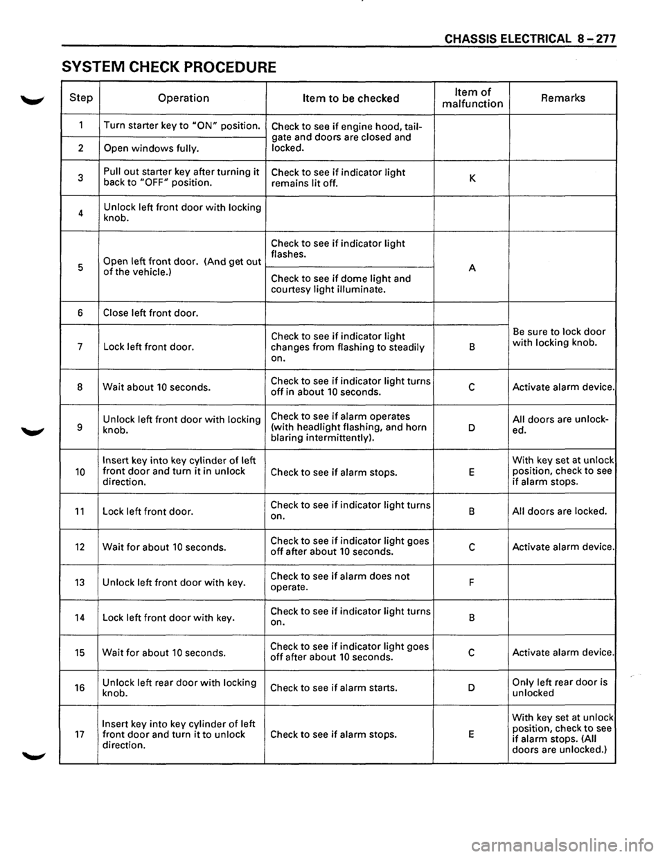
CHASSIS ELECTRICAL 8 ~ 277
SYSTEM CHECK PROCEDURE
Step Operation Item to be checked Item of Remarks malfunction
1
Turn starter key to "ON" position. Check to see if engine hood, tail-
gate and doors are closed and
2
Open windows fully. locked.
3
Pull out starter key after turning it Check to see if indicator light K back to "OFF" position.
remains lit off.
4 Unlock
left
front door with locking
knob.
Check to see if indicator light
Open left front door. (And get out flashes.
5 A
of the vehicle.) Check to see if dome light and
courtesy light illuminate.
6 Close left front door.
Check to see if indicator light Be sure to lock door
7
Lock left front door.
changes from flashing to steadily B with locking knob.
on.
8 Wait about 10 seconds. Check to see if indicator light turns c Activate alarm device. off in about 10 seconds.
Unlock left
front door with locking Check to see if alarm operates All doors are unlock-9 knob. (with
headlight flashing, and horn D ed.
blaring intermittently).
Insert key into key cylinder of left With
key set at unlock
10 front door and turn it in unlock Check to see if alarm stops. E position, check to see
direction. if alarm stops.
11 Lock left front door. Check to see if indicator light turns
B All doors are locked.
on.
12 Wait for about 10 seconds. Check to see if indicator light goes c Activate alarm device. off after about 10 seconds.
13 Unlock left front door with key. Check to see if alarm does not F
operate.
14 Lock left front door with key. Check to see if indicator light turns
B
on.
15 Wait for about 10 seconds. Check to see if indicator light goes c Activate alarm device. off after about 10 seconds.
16 Unlock left rear door with locking Check to see if alarm starts. D Only left rear door is
knob. unlocked
Insert key
into key cylinder of left With
key set at unlock
position, check to see 17 front door and turn it to unlock Check to see if alarm stops. E if alarm stops. (All direction.
doors are unlocked.)
Page 1470 of 1928
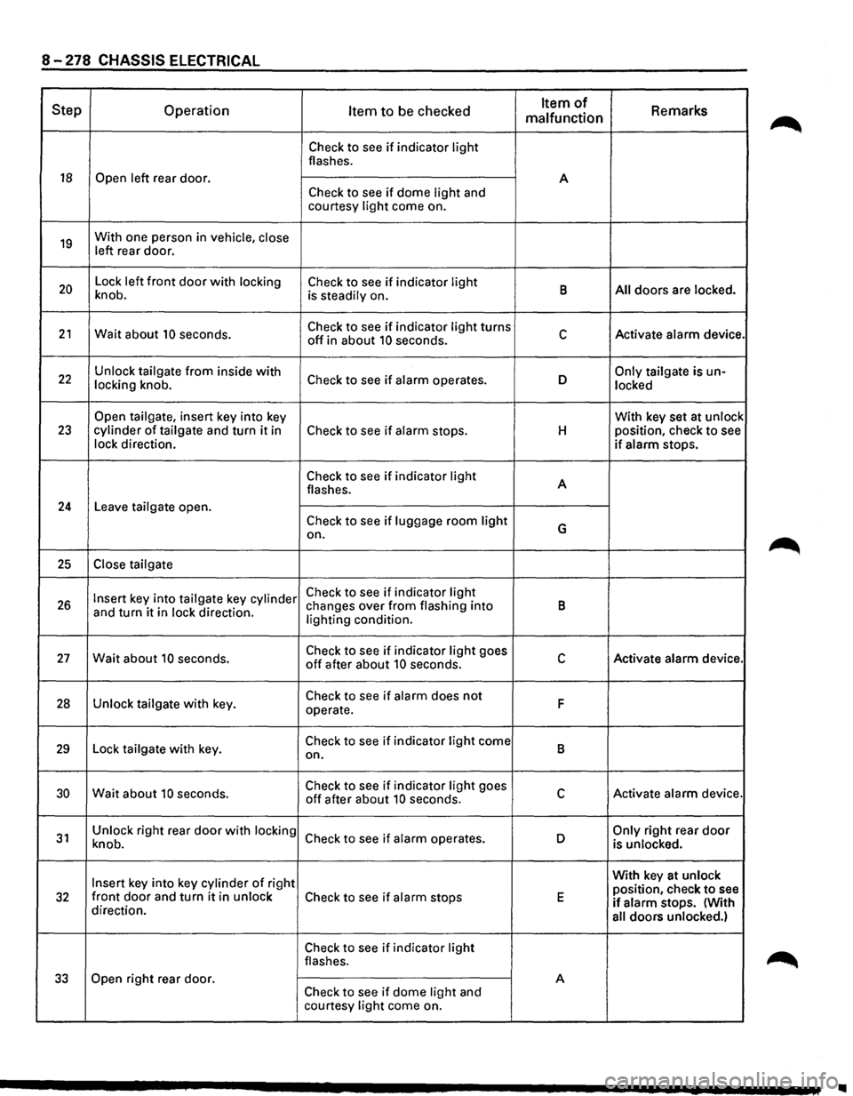
8-278 CHASSIS ELECTRICAL
Step Operation Item to be checked Item of Remarks malfunction
Check to see if indicator light flashes.
18 Open left rear door.
A
Check to see if dome light and
courtesy light come on.
19 With one person in vehicle, close
left rear door.
20 Lock left front door with locking Check to see if indicator light B All doors are locked.
knob. is steadily on.
21 Wait about 10 seconds. Check to see if indicator light turns c Activate alarm device. off in about 10 seconds.
22 Unlock tailgate from inside with Check to see if alarm operates. D Only tailgate is un-
locking knob.
locked
Open tailgate, insert key into key With key set at unlock 23 cylinder of tailgate and turn it in Check to see if alarm stops. H position,
check to see
lock direction. if alarm stops.
Check to see if indicator light A
flashes.
24 Leave tailgate open.
Check to see if luggage room light G on.
25 Close tailgate
Insert key into tailgate key cylinder Check to see if indicator light 26 and turn it in lock direction. changes
over from flashing into B lighting condition.
27 Wait about 10 seconds. Check to see if indicator light goes c Activate alarm device. off after about 10 seconds.
28 Unlock tailgate with key. Check to see if alarm does not F operate.
29 Lock tailgate with key. Check to see if indicator light come B on.
30 Wait about 10 seconds. Check to see if indicator light goes c Activate alarm device. off after about 10 seconds.
31 Unlock right rear door with locking Check to see if alarm operates.
D Only right rear door knob.
is unlocked.
Insert key into key cylinder of right With
key at unlock
position, check to see 32 front door and turn it in unlock Check to see if alarm stops E if alarm stops. (With
direction.
all doors unlocked.)
Check to see if indicator light flashes.
33 Open right rear door.
A Check to see if dome light and
courtesy light come on.
..
Page 1472 of 1928
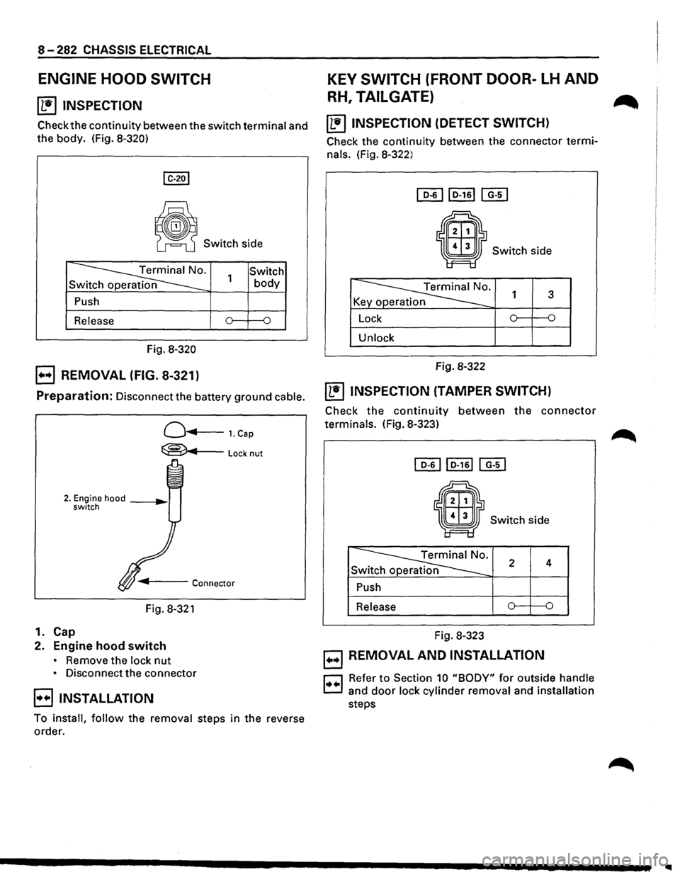
8-282 CHASSIS ELECTRICAL
ENGINE HOOD SWITCH
~ INSPECTION
Check the continuity between the switch terminal and
the body. (Fig. 8-320)
~ Switch side
~· Sw
Push
Release
Fig.
8-320
E) REMOVAL (FIG. 8-321)
Switch 1 body
Preparation: Disconnect the battery ground cable.
Q...,..,...___ 1. Cap
~Locknut
Fig. 8-321
1. Cap
2. Engine hood switch
• Remove the lock nut
• Disconnect the connector
B INSTALLATION
To install, follow the removal steps in the reverse
order.
KEY SWITCH (FRONT DOOR-LH AND
RH, TAILGATE) ...
~ INSPECTION (DETECT SWITCH)
Check the continuity between the connector termi
nals. (Fig. 8-322)
Switch side
~· K y p 1 3
Lock 0 {)
Unlock
Fig. 8-322
~ INSPECTION (TAMPER SWITCH)
Check the continuity between the connector
terminals. (Fig. 8-323)
• Switch side
~· Sw 2 4
Push
Release
Fig. 8-323
B REMOVAL AND INSTALLATION
r::J Refer to Section 10 "BODY" for outside handle
c:.:J and door lock cylinder removal and installation
steps
Page 1473 of 1928
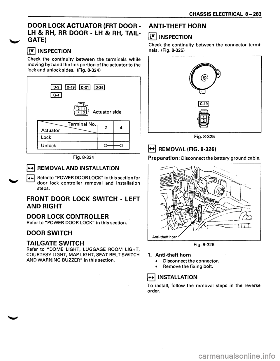
DOOR LOCK ACTUATOR (fRT DOOR
LH & RH, RR DOOR -LH & RH, TAIL-
~ GATE)
~ INSPECTION
Check the continuity between the terminals while
moving by hand the link portion of the actuator to the
lock and unlock sides. (Fig. 8-324)
[QI] I D-191 I D-211 I D-261
[E)
~
~ Actuator side
~· 2 4 r
Lock
Unlock
Fig. 8-324
B REMOVAL AND INSTALLATION
1++1 Referto "POWER DOOR LOCK" in this section for
door lock controller removal and installation
steps.
FRONT DOOR LOCK SWITCH -LEFT
AND RIGHT
DOOR LOCK CONTROLLER
Refer to "POWER DOOR LOCK" in this section.
DOOR SWITCH
CHASSIS ELECTRICAL 8-283
ANTI-THEFT HORN
~ INSPECTION
Check the continuity between the connector termi
nals. (Fig. 8-325)
Fig. 8-325
B REMOVAL (FIG. 8-326)
Preparation: Disconnect the battery ground cable.
TAILGATE SWITCH Fig. 8-326
Refer
to "DOME LIGHT, LUGGAGE ROOM LIGHT,
COURTESY LIGHT,
MAP LIGHT, SEAT BELT SWITCH 1. Anti-theft horn
AND WARNING BUZZER" in this section. • Disconnect the connector.
• Remove the fixing bolt.
B INSTALLATION
To install, follow the removal steps in the reverse
order.
Page 1476 of 1928
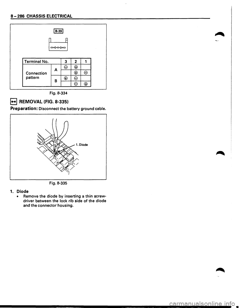
8-286 CHASSIS ELECTRICAL
Terminal No. 3
A e
Connection
pattern
8 <±>
Fig. 8-334
B REMOVAL (FIG. 8-335)
2 1
<±>
<±>
e
e
e
<±>
Preparation: Disconnect the battery ground cable.
Fig. 8-335
1. Diode
• Remove the diode by inserting a thin screw
driver between the
lock rib side of the diode
and the connector housing.
Page 1518 of 1928
8-328 CHASSIS ELECTRICAL
A/T INDICATOR LIGHT BULB
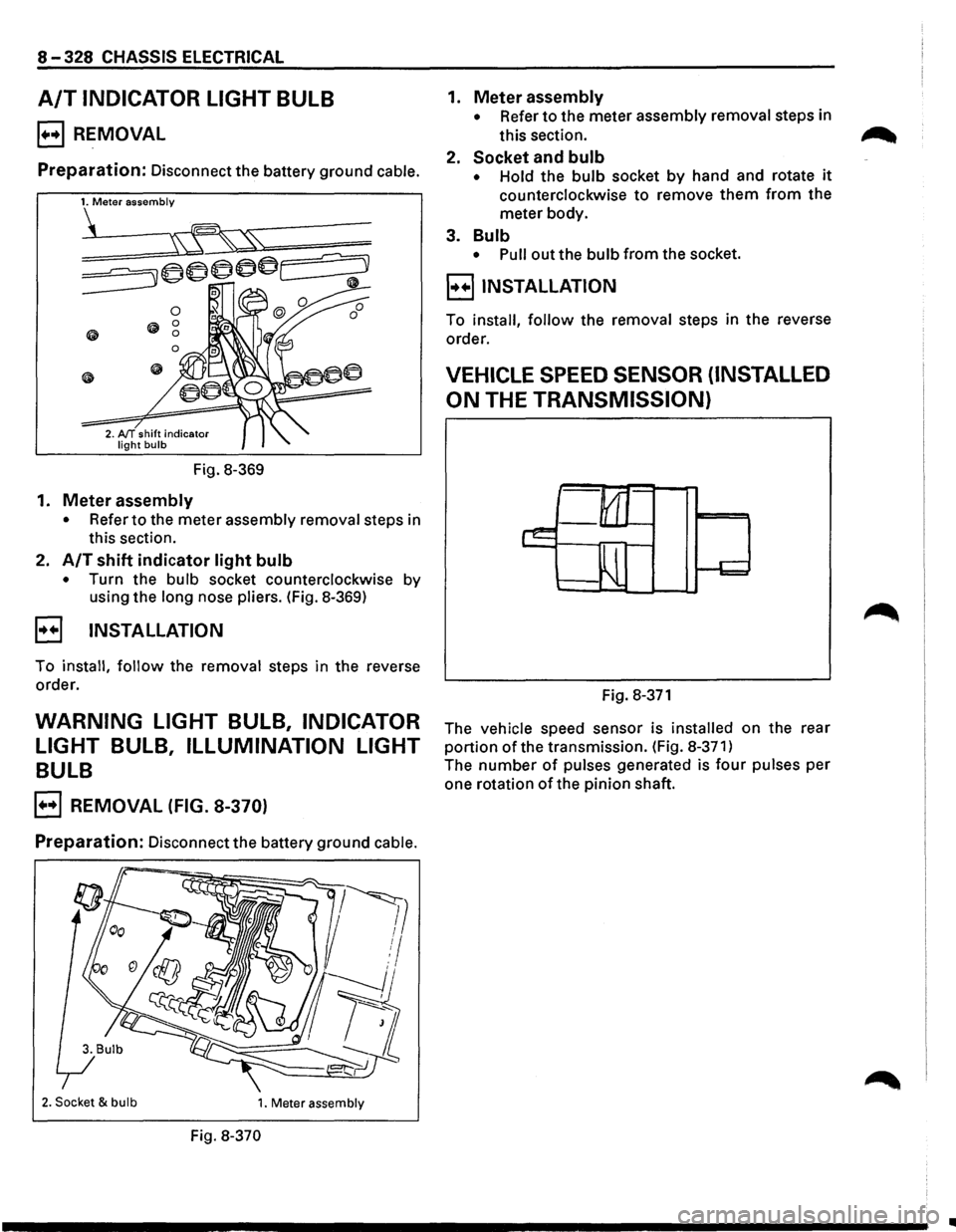
B REMOVAL
Preparation: Disconnect the battery ground cable.
Fig.
8-369
1. Meter assembly
• Refer to the meter assembly removal steps in
this section.
2.
A/T shift indicator light bulb
• Turn the bulb socket counterclockwise by
using the
long nose pliers. (Fig. 8-369)
B INSTALLATION
To install, follow the removal steps in the reverse
order.
WARNING LIGHT BULB, INDICATOR
LIGHT
BULB, ILLUMINATION LIGHT
BULB
B REMOVAL (FIG. 8-370)
Preparation: Disconnect the battery ground cable.
2. Socket & bulb 1. Meter assembly
Fig. 8-370
1. Meter assembly
• Refer to the meter assembly removal steps in
this section.
2.
Socket and bulb
• Hold the bulb socket by hand and rotate it
counterclockwise to remove them from the
meter body.
3.
Bulb
• Pull out the bulb from the socket.
B INSTALLATION
To install, follow the removal steps in the reverse
order.
VEHICLE SPEED SENSOR (INSTALLED
ON
THE TRANSMISSION)
Fig. 8-371
The vehicle speed sensor is installed on the rear
portion of the transmission. (Fig. 8-371)
The number of pulses generated is four pulses per
one rotation
of the pinion shaft.
..
Page 1570 of 1928
8-380 CHASSIS ELECTRICAL
STARTER SWITCH
Refer to "START AND CHARGING" in this section.
SEAT HEATER SWITCH
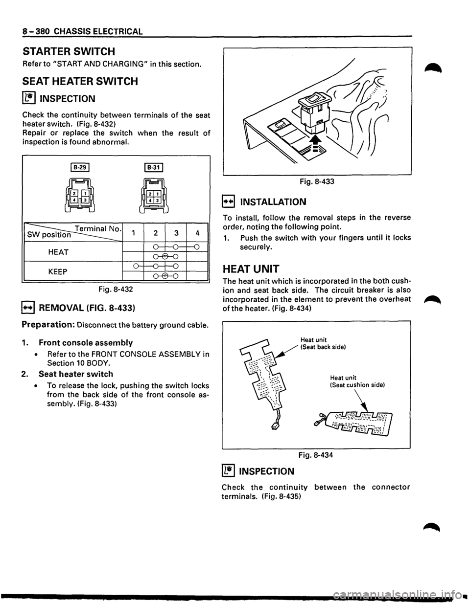
~ INSPECTION
Check the continuity between terminals of the seat
heater switch. (Fig. 8-432)
Repair
or replace the switch when the result of
inspection is found abnormal.
I B-291 I B-31 I
ji
8
s ~0. 1 2 3 4
HEAT o--:---0= f--0
o-6--0
o---0---j-0 KEEP o-6--0
Fig. 8-432
B REMOVAL (FIG. 8-433)
Preparation: Disconnect the battery ground cable.
1. Front console assembly
• Refer to the FRONT CONSOLE ASSEMBLY in
Section 10 BODY.
2. Seat heater switch
• To release the lock, pushing the switch locks
from the back side of the front console as
sembly. (Fig. 8-433) Fig.
8-433
B INSTALLATION
To install, follow the removal steps in the reverse
order, noting the
following point.
1. Push the switch with your fingers until it locks
securely.
HEAT UNIT
The heat unit which is incorporated in the both cush
ion and seat back side. The circuit breaker is also
incorporated in the element to prevent the overheat ~
of the heater. (Fig. 8-434)
Heat unit
(Seat back side)
Heat
unit (Seat cushion side)
Fig. 8-434
~ INSPECTION
Check the continuity between the connector
terminals. (Fig. 8-435)
..
Page 1580 of 1928
9A-4 RADIO
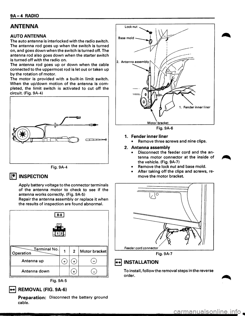
ANTENNA
AUTO ANTENNA
The auto antenna is interlocked with the radio switch.
The antenna rod goes up when the switch is turned
on, and goes
down when the switch is turned off. The
antenna rod
also goes down when the starter switch
is turned
off with the radio on.
The antenna rod goes up
or down when the cable
connected to the uppermost rod is let out or taken up
by the rotation of motor.
The
motor is provided with a built-in limit switch.
When the up/down
motion of the antenna is com
pleted, the
limit switch is activated to cut off the
circuit. (Fig. 9A-4)
0
Fig. 9A-4
(1!] INSPECTION
Apply battery voltage to the connector terminals
of the antenna motor to check to see if the
antenna works correctly. (Fig. 9A-5)
Repair the antenna assembly
or replace it when
the results
of inspection are found abnormal.
[EJ
~
~0. Op 1 2 Motor bracket
Antenna up
G
Antenna down
Fig. 9A-5
B REMOVAL (FIG. 9A-6)
G G
G G
Preparation: Disconnect the battery ground
cable.
Locknut~
B"e mold --b I
___,
------------
1. Fender inner liner
Fig. 9A-6
1. Fender inner liner
• Remove three screws and nine clips.
2. Antenna assembly
• Disconnect the feeder cord and the an
tenna
motor connector at the inside of
the vehicle. (Fig. 9A-7)
• Remove the lock nut and base mold.
• After taking off the clips and screws, re
move the motor bracket.
lJO
Feeder cord connector
Fig. 9A-7
E) INSTALLATION
To install, follow the removal steps in the reverse
order.
Page 1581 of 1928
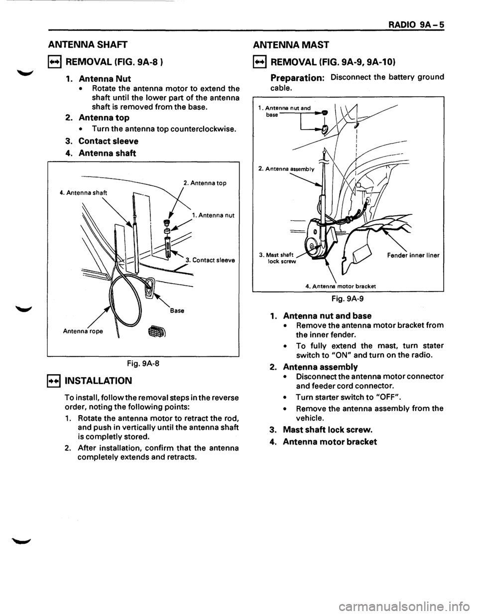
ANTENNA SHAFT
B REMOVAL (FIG. 9A-8 )
1. Antenna Nut
• Rotate the antenna motor to extend the
shaft
until the lower part of the antenna
shaft is removed from the base.
2.
Antenna top
• Turn the antenna top counterclockwise.
3.
Contact sleeve
4. Antenna shaft
Fig. 9A-8
B INSTALLATION
2. Antenna top
Base
To install, follow the removal steps in the reverse
order, noting the
following points:
1. Rotate the antenna motor to retract the rod,
and push in
vertically until the antenna shaft
is
completly stored.
2. After installation, confirm that the antenna
completely extends and retracts.
RADIO 9A-5
ANTENNA MAST
B REMOVAL (FIG. 9A-9, 9A-10)
Preparation: Disconnect the battery ground
cable.
4. Antenna motor brecket
Fig. 9A-9
1.
Antenna nut and base
• Remove the antenna motor bracket from
the inner fender.
• To fully extend the mast, turn stater
switch
to "ON" and turn on the radio.
2.
Antenna assembly
• Disconnect the antenna motor connector
and feeder cord connector.
• Turn starter switch to "OFF".
•
Remove the antenna assembly from the
vehicle.
3. Mast shaft lock screw.
4. Antenna motor bracket