ISUZU TROOPER 1995 Workshop Manual
Manufacturer: ISUZU, Model Year: 1995, Model line: TROOPER, Model: ISUZU TROOPER 1995Pages: 1928
Page 551 of 1928
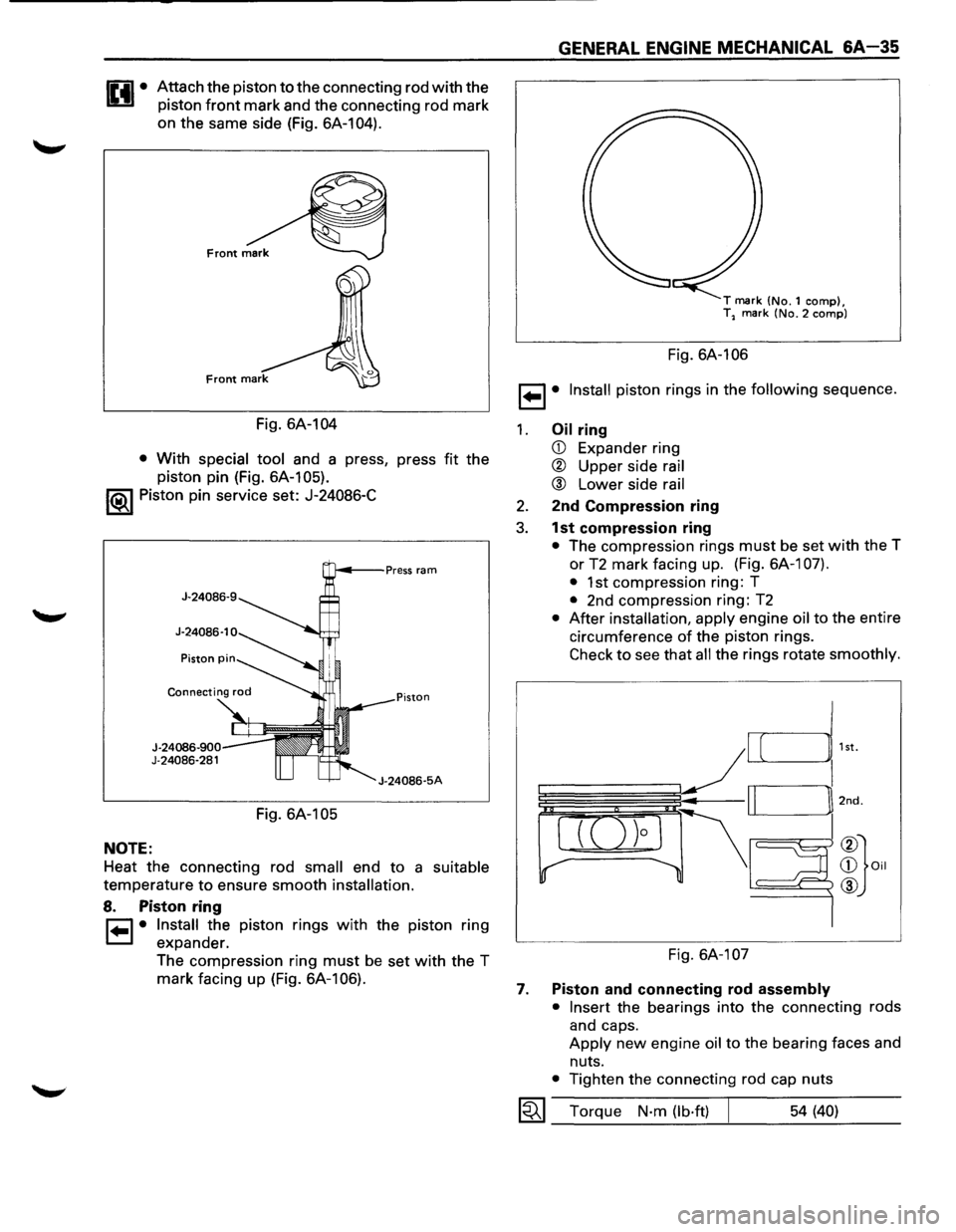
Attach the piston to the connecting rod with the
piston
front mark and the connecting rod mark
on the same side (Fig. 6A-104).
Fig. 6A-104
• With special tool and a press, press fit the
piston pin (Fig. 6A-105).
1®1 Piston pin service set: J-24086-C
NOTE:
J-24086-900 J-24086-281
Fig. 6A-105
J-24086-5A
Heat the connecting rod small end to a suitable
temperature to ensure smooth installation.
8. Piston ring
r=1 • Install the piston rings with the piston ring
1=.1 expander.
The compression ring
must be set with the T
mark facing up (Fig. 6A-106).
GENERAL ENGINE MECHANICAL &A-35
T mark (No.1 comp), T2 mark (No.2 comp)
Fig. 6A-106
1 ... 1• Install piston rings in the following sequence.
1. Oil ring
CD Expander ring
® Upper side rail
® Lower side rail
2. 2nd Compression ring
3. 1st compression ring
• The compression rings must be set with the T
or
T2 mark facing up. (Fig. 6A-1 07).
•
1st compression ring: T
• 2nd compression ring: T2
• After installation, apply engine oil to the entire
circumference
of the piston rings.
Check to see that all the rings rotate smoothly.
Fig. 6A-107
7. Piston and connecting rod assembly
• Insert
the bearings into the connecting rods
and caps.
Apply new engine oil to the bearing faces and
nuts.
• Tighten the connecting rod cap nuts
1~1 Torque N·m (lb·ft) 54 (40)
Page 552 of 1928
SA-36 GENERAL ENGINE MECHANICAL
NOTE:
• Do not apply engine oil to the bearing back
faces and connecting rod bearing fitting
surfaces.
6. Oil gallery
• Refer to Section 6A 1 "Crankshaft and main
bearing" installation.
5. Oil strainer and rubber ring
4. Oil pipe and rubber ring
3. Oil pan
• Refer to Section 6A1 "Oil pan installation".
2. Cylinder head gasket
1. Cylinder head assembly
• Refer to section 6A 1 "Cylinder head assembly
installation".
•
Page 553 of 1928
GENERAL ENGINE MECHANICAL 6A-37
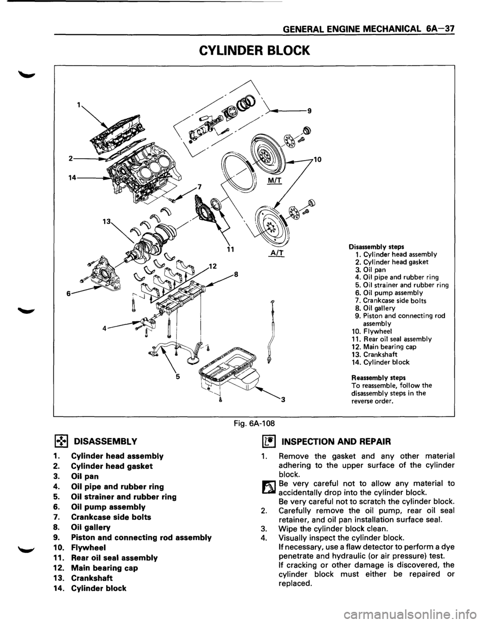
CYLINDER BLOCK
1.,!•1 DISASSEMBL V
1. Cylinder head assembly
2. Cylinder head gasket
3. Oil pan
4. Oil pipe and rubber ring
5. Oil strainer and rubber ring
6. Oil pump assembly
7. Crankcase side bolts
8. Oil gallery
9. Piston and connecting rod assembly
1 0. Flywheel
11. Rear oil seal assembly
12. Main bearing cap
13. Crankshaft
14.
Cylinder block
Fig. 6A-108
Disassembly steps
1. Cylinder head assembly
2. Cylinder head gasket
3. Oil pan
4. Oil pipe and rubber ring
5.
Oil strainer and rubber ring
6. Oil pump assembly
7. Crankcase side bolts
8.
Oil gallery
9. Piston and connecting rod
assembly
10. Flywheel
11. Rear oil seal assembly
12. Main bearing cap
13. Crankshaft
14.
Cylinder block
Reassembly steps
To reassemble, follow the disassembly steps in the reverse order.
(1!] INSPECTION AND REPAIR
1. Remove the gasket and any other material
adhering to the upper surface of the cylinder
block.
m Be very careful not to allow any material to
LQI accidentally drop into the cylinder block.
Be very careful not to scratch the cylinder block.
2. Carefully remove the oil pump, rear oil seal
retainer, and oil pan installation surface seal.
3. Wipe the cylinder block clean.
4. Visually inspect the cylinder block.
If
necessary, use a flaw detector to perform a dye
penetrate and
hydraulic (or air pressure) test.
If cracking or other damage is discovered, the
cylinder block must either be repaired or
replaced.
Page 554 of 1928
L
6A-38 GENERAL ENGINE MECHANICAL
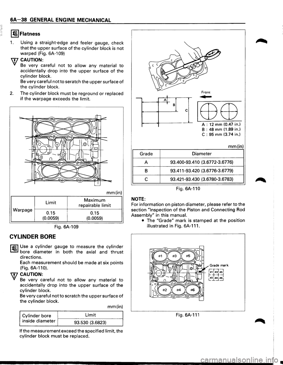
I @.I Flatness
1. Using a straight-edge and feeler gauge, check
that the upper surface of the cylinder block is not
warped (Fig.
6A-109)
\fl CAUTION:
VI Be very careful not to allow any material to
accidentally drop into the upper surface of the
cylinder block.
Be very careful not to seratch the upper surface of
the cylinder block.
2. The cylinder block must be reground or replaced
if the warpage exceeds the limit.
Warpage Limit 0.15
(0.0059)
mm(in)
Maximum
repairable limit
0.15
(0.0059)
Fig. 6A-1 09
CYLINDER BORE
l'fil Use a cylinder gauge to measure the cylinder
1..!:.1 bore diameter in both the axial and thrust
directions.
Each measurement
should be made at six points
(Fig. 6A-110).
\fl CAUTION:
VI Be very careful not to allow any material to
accidentally drop into the upper surface of the
cylinder block.
Be very careful not to scratch the upper surface of
the cylinder block.
Cylinder
bore
inside diameter Limit
93.530 (3.6823) mm(in)
lfthe measurement
exceed the specified limit, the
cylinder block must be replaced.
j -A] I B
c
--~ lED ED
A : 12 mm (0.47 in.)
B : 48 mm (1.89 in.)
C : 95 mm (3.74 in.)
mm(in)
Grade Diameter
A 93.400-93.41
0 (3.6772-3.6776)
B 93.411-93.420 (3.6776-3.6779)
c 93.421-93.430 (3.6780-3.6783)
Fig.
6A-110
NOTE:
For information on piston diameter, please refer to the
section
"Inspection of the Piston and Connecting Rod
Assembly" in this manual.
•
The "Grade" mark is stamped at the position
illustrated in Fig. 6A-111.
Grade mark
-+lllf++---+-+1-'--"--tt.:-H----:!+--~=rt--r;,T#;T ;1 ~+=+=J ~~~
Fig. 6A-111
•
Page 555 of 1928
1,.!.,1 REASSEMBLY
14. Cylinder block
13. Crankshaft
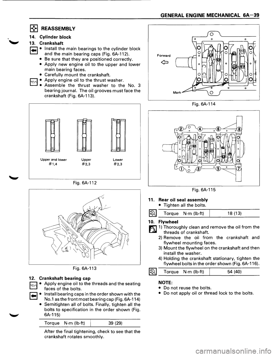
1•1• Install the main bearings to the cylinder block
and the main bearing caps (Fig. 6A-112).
• Be sure that they are positioned correctly.
•
Apply new engine oil to the upper and lower
main bearing faces.
• Carefully mount the crankshaft.
1~·1 .• Apply engine oil to the thrust washer.
Assemble the thrust washer to the No. 3
bearing
journal. The oil grooves must face the
crankshaft (Fig. 6A-113).
r--!::"
11-1
~
Upper and lower
#1,4
Upper
#2,3
Fig. 6A-112
Fig. 6A-113
12. Crankshaft bearing cap
Lower
#2,3
D • Apply engine oil to the threads and the seating
L:J faces of the bolts.
I• I• Install bearing caps in the order shown with the
No.1 as the front most bearing cap (Fig. 6A-114)
• Semitighten all of bolts. Finally, tighten all the
bolts to specification in the order shown (Fig.
6A-115)
Torque
N·m (lb·ft) 39 (29)
After the final tightening, check to see that the
crankshaft rotates
smoothly.
GENERAL ENGINE MECHANICAL &A-39
Forward
Fig. 6A-114
Fig. 6A-115
11. Rear oil seal assembly
• Tighten all the bolts.
~~~ Torque N·m (lb·ft)
1 0. Flywheel
18 (13)
r:l]1) Thoroughly clean and remove the oil from the
threads
of crankshaft.
2) Remove the oil from the crankshaft and
flywheel mounting faces.
3) Mount the flywheel on the crankshaft and then
install the washer.
4) Holding the crankshaft stationary, tighten the
flywheel bolts in the order shown (Fig. 6A-116).
~~~ Torque N·m (lb·ft) 54 (40)
NOTE:
•
Do not reuse the bolts.
•
Do not apply oil or thread lock to the bolts.
Page 556 of 1928
6A-40 GENERAL ENGINE MECHANICAL
Fig. 6A-116
9. Piston and connecting rod assembly.
Cl • Apply engine oil to the cylinder bores, the
L:J connecting rod bearings and the crankshaft
pins.
NOTE:
Do not apply engine oil to the bearing back
faces and the connecting rod bearing fitting
surfaces.
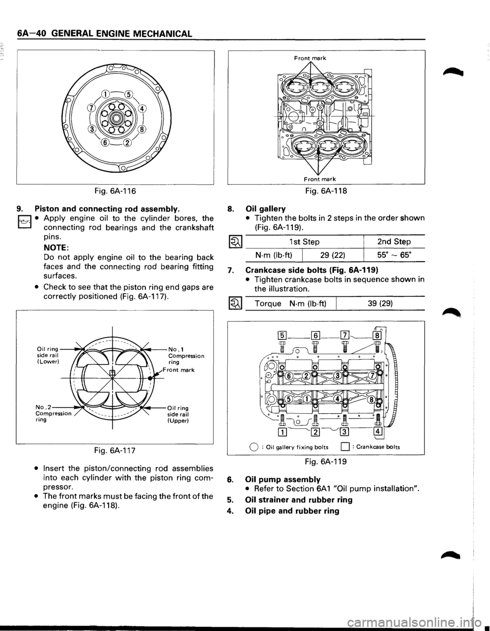
• Check to see that the piston ring end gaps are
correctly positioned (Fig. 6A-117).
Oil ring--~~~=!==:::;:,.::~~--No.1 side rail Compression (Lower) ring
Front mark
No. 2--~~~~i::::::=~~;(.,.--Oil ring Compression side rail ring (Upper)
Fig. 6A-117
• Insert the piston/connecting rod assemblies
into each cylinder with the piston ring com
pressor.
• The front marks must be facing the front of the
engine (Fig. 6A-118).
8.
Front mark
Front mark
Fig. 6A-118
Oil gallery
• Tighten the bolts in 2 steps in the order shown
(Fig. 6A-119).
1~1 _________ 1s_t,s_te~p ________ +-_2_n_d_S_t_e_p ___
7.
N·m (lb·ftl 29 (22) ss· -ss·
Crankcase side bolts (Fig. &A-119)
• Tighten crankcase bolts in sequence shown in
the
illustration.
I~I __ T_o_r~qu_e __ N_·_m __ (lb_·ft_)~ ______ 3_9_(2_9_l ____ _
Q : Oil gallery fixing bolts 0 : Crankcase bolts
Fig. 6A-119
6. Oil pump assembly
• Refer to Section 6A 1 "Oil pump installation".
5. Oil strainer and rubber ring
4.
Oil pipe and rubber ring
•
Page 557 of 1928
3. Oil pan
m 1) Completely remove all residual sealant,
t..al lubricant and moisture from the sealing
surfaces. The surfaces must be perfectly dry.
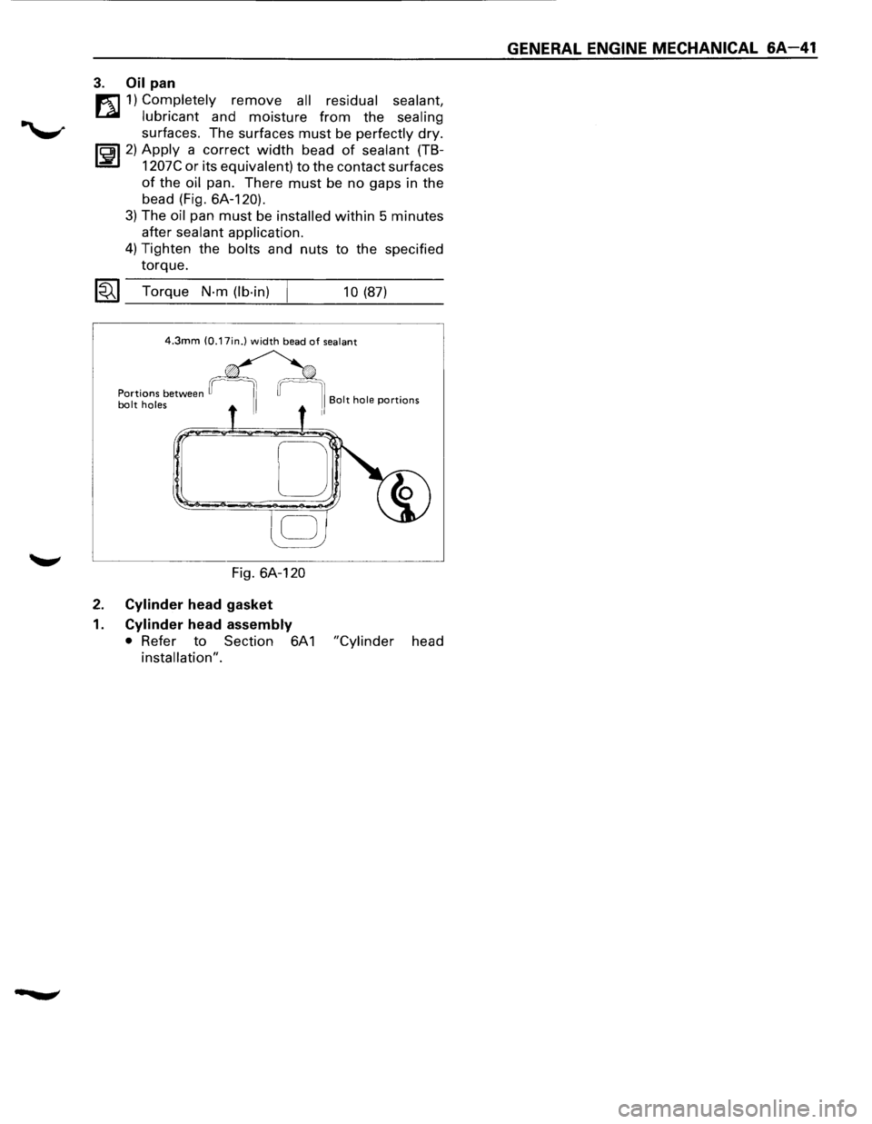
li5il 2) Apply a correct width bead of sealant (TB
L::!i!J 1207C or its equivalent) to the contact surfaces
of the oil pan. There must be no gaps in the
bead (Fig. 6A-120).
3) The oil pan must be installed within 5 minutes
after sealant application.
4) Tighten the bolts and nuts to the specified
torque.
1«.1 Torque N·m (lb-in) 10 (87)
4.3mm (0.17in.) width bead of sealant
Fig. 6A-120
2. Cylinder head gasket
1. Cylinder head assembly
• Refer to Section 6A 1 "Cylinder head
installation".
GENERAL ENGINE MECHANICAL 6A-41
Page 558 of 1928
MEMO
•
Page 559 of 1928
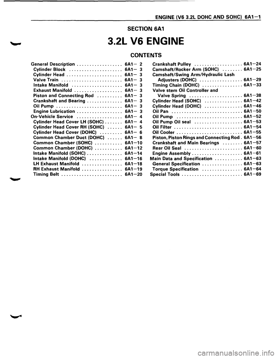
ENGINE (V6 3.2L DOHC AND SOHC) 6A 1-1
SECTION 6A1
3.2L V6 ENGINE
CONTENTS
General Description .................. 6A1-2 Crankshaft Pulley ................... 6A1-24
Cylinder Block . . . . . . . . . . . . . . . . . . . . . 6A 1-3 Camshaft/Rocker Arm (SOHC) ........ 6A1-25
Cylinder Head ...................... 6A1-3 Camshaft/Swing Arm/Hydraulic Lash
Valve Train ........................ 6A1-3 Adjusters (DOHC) ................. 6A1-29
Intake Manifold .................... 6A1-3 Timing Chain (DOHC) ................ 6A1-33
Exhaust Manifold ................... 6A1-3 Valve stem Oil Controller and
Piston and
Connecting Rod .......... 6A1-3 Valve Spring ..................... 6A1-38
Crankshaft and Bearing .............. 6A1-3 Cylinder Head (SOHC) ............... 6A1-42
Oil Pump .......................... 6A1-3 Cylinder Head (DOHC) ............... 6A1-46
Engine Lubrication . . . . . . . . . . . . . . . . . . 6A 1-3 Oil Pan ............................ 6A 1-50
On-Vehicle Service . . . . . . . . . . . . . . . . . . 6A1-4 Oil Pump .......................... 6A 1-52
Cylinder Head Cover LH (SOHC) ....... 6A1-4 Oil Pump Oil seal ................... 6A 1-53
Cylinder Head Cover RH (SOHC) ...... 6A1-5 Oil Filter ........................... 6A 1-54
Cylinder Head Cover (DOHC) . . . . . . . . . 6A 1-6 Oil Cooler .......................... 6A 1-55
Common Chamber Duct (DOHC) ...... 6A1-8 Piston, Piston Rings and Connecting Rod . 6A 1-56
Common Chamber (SOHC) ........... 6A1-10 Crankshaft and Main Bearings ........ 6A1-57
Common Chamber (DOHC) ........... 6A1-12 Rear Oil Seal ....................... 6A1-60
Intake Manifold (SOHC) .............. 6A1-14 Engine Assembly .................... 6A1-61
Intake Manifold (DOHC) ............. 6A1-16 Main Data and Specification ........... 6A1-63
LH Exhaust Manifold . . . . . . . . . . . . . . . . 6A 1-18 General Specification ................ 6A 1-63
RH Exhaust Manifold ................ 6A1-19 Torque Specification ................ 6A1-64
Timing Belt ........................ 6A1-20 Special Tools ........................ 6A1-69
Page 560 of 1928
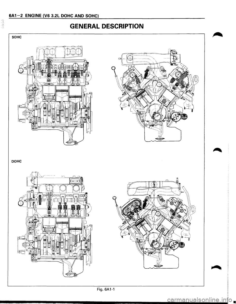
6A 1-2 ENGINE (V6 3.2L DOHC AND SOHC)
GENERAL DESCRIPTION
SOHC
DOHC
Fig. 6A1-1
•