ISUZU TROOPER 1995 Workshop Manual
Manufacturer: ISUZU, Model Year: 1995, Model line: TROOPER, Model: ISUZU TROOPER 1995Pages: 1928
Page 561 of 1928
CYLINDER BLOCK
The cylinder block is made of aluminum die-cast
casting
for 75° V-type six cylinders. It has a rear plate
integrated structure and employs a deep skirt. The
cylinder liner is cast and the liner inner diameter and
crankshaft
journal diameter are classified into grades.
The crankshaft is supported by four bearings
of which
width is different between No.2, No.3 and No.1, No.4;
the
width of No.3 bearing on the body side is different
in order
to support the thrust bearing. The bearing cap
is made
of nodular cast iron and each bearing cap uses
four bolts and two side bolts.
CYLINDER HEAD
The cylinder head, made of aluminum alloy casting
employs a pent-roof type combustion chamber with a
spark
plug in the center.
The intake and exhaust
valves are placed in V-type
design. The ports are cross-flow type.
VALVE TRAIN
SOHC: The camshafts on both banks are driven by a
timing
belt to operate the valves via rocker arm.
No
further valve clearance adjustment is
required, due
to the Hydraulic lash adjuster
attachedtotherockerarm.
DOHC: Intake camshaft on the both sides of banks are
driven through a
timing belt, while exhaust
camshaft are driven by the both sides
of intake
camshaft through chains.
The driven camshafts open and
close valves
through swing arms.
Valve clearance is automatically adjusted by
means
of HLA built in the cylinder head.
INTAKE MANIFOLD
SOHC: The intake manifold system is composed ofthe
aluminum cast common chamber and intake
manifold attached with six fuel injectors.
DOHC: The intake manifold system is composed of the
aluminum cast common chamber duct having
the induction
control valve, common chamber
and intake
manifold attached with six fuel
injectors.
EXHAUST MANIFOLD
The exhaust manifold is made of nodular cast iron.
PISTONS AND CONNECTING RODS
Aluminum pistons are used after selecting the grade
that meets the cylinder bore diameter. Each piston has
two compression rings and one oil ring. The piston pin
made
of chromium steel is offset 1 mm toward the
thrust side, and the thrust pressure
of piston to the
cylinder wall varies gradually as the piston travels. The
connecting rods are made
of forged steel. The
connecting rod bearings are graded
for correct size
selection.
ENGINE (V6 3.2L DOHC AND SOHC) 6A1-3
CRANKSHAFT AND BEARINGS
The crankshaft is made of Ductile cast-iron.Pins and
journals are graded for correct size selection for their
bearing.
OIL PUMP
The trochoid-type oil pump is driven by crankshaft.
Operation and service procedures are described in this
section.
ENGINE LUBRICATION
The oil discharged by a trochoid-type oil pump driven
by the crankshaft is fed through full-flow oil filter and
engine
coolant cooled oil cooler up to the oil gallery
provided under the crankshaft bearing cap. The oil is
then
led to the crankshaft journals and cylinder head.
The crank pins are
lubricated with oil from crankshaft
journals through oil holes. Also, an oil jet is fed to each
cylinder from crankshaft journals on the connecting
rod
for piston cleaning. The oil pan flange is sealed with
liquid packing only; do not deform or damage the
flange surface during removal or installation.
Page 562 of 1928
6A1-4 ENGINE (V6 3.2L DOHC AND SOHC)
ON-VEHICLE SERVICE
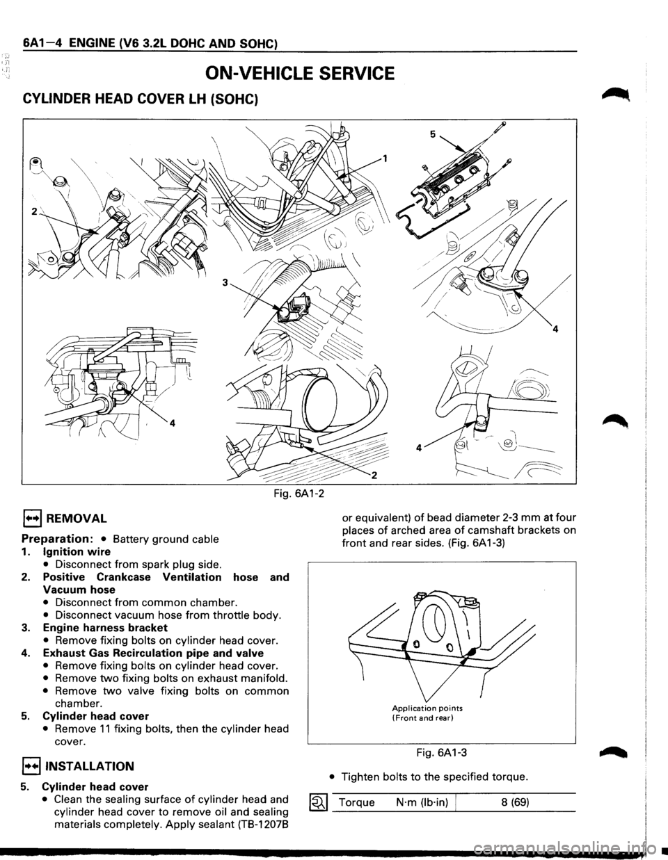
CYLINDER HEAD COVER LH (SOHC)
1••1 REMOVAL
Preparation: • Battery ground cable
1. Ignition wire
• Disconnect from spark plug side.
2. Positive Crankcase Ventilation hose and
Vacuum hose
• Disconnect from common chamber.
• Disconnect vacuum hose from throttle body.
3. Engine harness bracket
• Remove fixing bolts on cylinder head cover.
4. Exhaust Gas Recirculation pipe and valve
• Remove fixing bolts on cylinder head cover.
• Remove two fixing bolts on exhaust manifold.
•
Remove two valve fixing bolts on common
chamber.
5. Cylinder head cover
• Remove 11 fixing bolts, then the cylinder head
cover.
I••IINST ALLA TION
5. Cylinder head cover
• Clean the sealing surface of cylinder head and
cylinder head cover to remove oil and sealing
materials completely.
Apply sealant (TB-12078
/
~
!8;
4
or equivalent) of bead diameter 2-3 mm at four
places of arched area of camshaft brackets on
front and rear sides. (Fig. 6A 1-3)
Application points (Front and rear)
Fig. 6A1-3
• Tighten bolts to the specified torque.
1~1 Torque N·m (lb·in) 8 (69)
•
Page 563 of 1928
4. Exhaust Gas Recirculation pipe and valve
• Tighten each fixing bolt to the specified torque.
Valve fixing bolt
1«1 Torque N·m (lb·in) 8 (69)
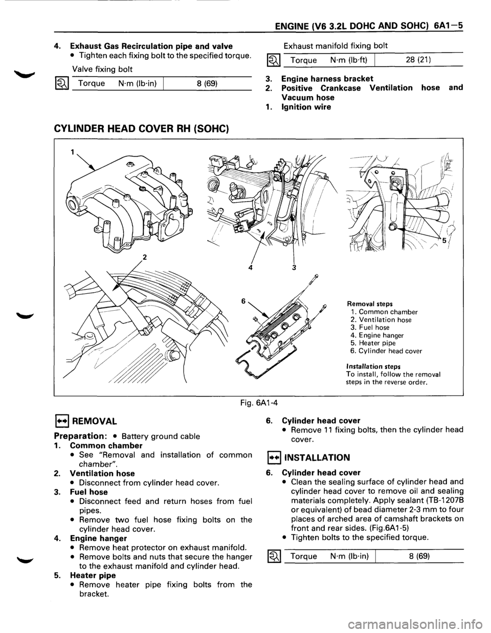
CYLINDER HEAD COVER RH (SOHC)
1
2
4
ENGINE (V6 3.2L DOHC AND SOHC) 6A1-5
Exhaust manifold fixing bolt
1«1 Torque N·m (lb·ft) I 28 (21)
3. Engine harness bracket
2. Positive Crankcase
Ventilation hose and
Vacuum hose
1. Ignition wire
3
Removal steps
1. Common chamber 2. Ventilation hose
3. Fuel hose
4. Engine hanger
5. Heater pipe
6.
Cylinder head cover
Installation steps
To install, follow the removal
steps in the reverse order.
Fig. 6A1-4
EJ REMOVAL
Preparation: • Battery ground cable
1. Common chamber
• See "Removal and installation of common
chamber".
2. Ventilation hose
• Disconnect from cylinder head cover.
3. Fuel hose
• Disconnect feed and return hoses from fuel
pipes.
• Remove two fuel hose fixing bolts on the
cylinder head cover.
4. Engine hanger
• Remove heat protector on exhaust manifold.
•
Remove bolts and nuts that secure the hanger
to the exhaust manifold and cylinder head.
5. Heater pipe
• Remove heater pipe fixing bolts from the
bracket.
6. Cylinder head cover
• Remove 11 fixing bolts, then the cylinder head
cover.
I•+IINSTALLATION
6. Cylinder head cover
• Clean the sealing surface of cylinder head and
cylinder head cover to remove oil and sealing
materials completely.
Apply sealant (TB-12078
or equivalent) of bead diameter 2-3 mm to four
places of arched area of camshaft brackets on
front and rear sides. (Fig.6A 1-5)
• Tighten bolts to the specified torque.
1«1 Torque N·m (lb·in) 8 (69)
Page 564 of 1928
6A1-6 ENGINE (V6 3.2L DOHC AND SOHC)
Application points (Front and rear)
Fig. 6A1-5
5. Heater pipe
• Tighten bolts to the specified torque.
~~~ Torque N·m (lb·ft) I 21 (15)
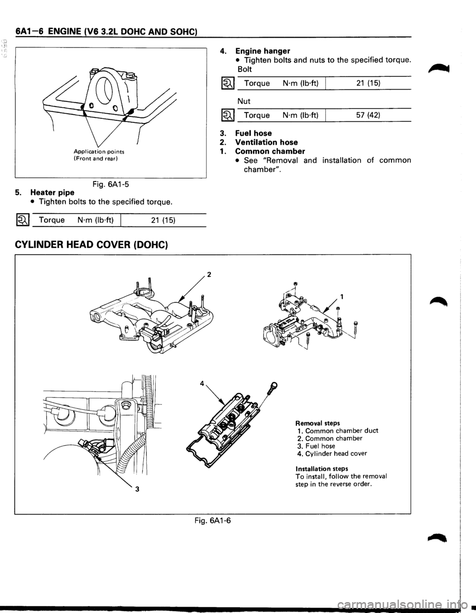
CYLINDER HEAD COVER (DOHC)
2
4
4. Engine hanger
• Tighten bolts and nuts to the specified torque.
Bolt
~~~ Torque N·m (lb·ft) 21 (15)
Nut
~~~ Torque N·m (lb·ft) 57 (42)
3. Fuel hose
2. Ventilation hose
1. Common chamber
• See "Removal and installation of common
chamber".
.J
Removal steps
1. Common chamber duct 2. Common chamber
3. Fuel hose
4. Cylinder head cover
Installation steps To install, follow the removal step in the reverse order.
Fig. 6A1-6
•
Page 565 of 1928
E) REMOVAL
Preparation: Battery ground
1. Common chamber duct
• Refer to "Common chamber removal and
installation" in this section.
2. Common chamber
• Refer to "Common chamber removal and
installation" in this section.
3. Fuel hose
• Disconnect feed and return hose from fuel pipe.
4. Cylinder head cover
I••IINSTALLATION
4. Cylinder head cover
• Clean the sealing surface of cylinder head and
cylinder head cover to remove oil and sealing
materials completely.
Apply sealant (TB-12078
or equivalent) of bead diameter 2-3 mm to four
places of arched area of camshaft brackets on
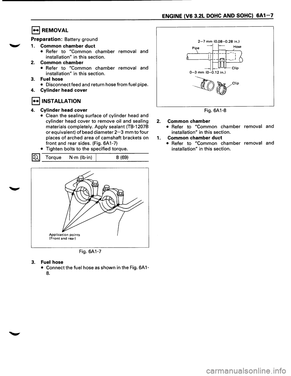
front and rear sides. (Fig. 6A 1-7)
• Tighten bolts to the specified torque.
1«1 Torque N·m (lb·in) 8 (69)
Application points (Front and rear)
Fig. 6A1-7
3. Fuel hose
• Connect the fuel hose as shown in the Fig. 6A 1-
8.
ENGINE (V6 3.2L DOHC AND SOHC) 6A 1-7
2-7 mm (0.08-0.28 in.)
r-
0-3 mm (0-0.12 in.)
·~(t)yCIIp
Fig. 6A1-8
2. Common chamber
• Refer to "Common chamber removal and
installation" in this section.
1. Common chamber duct
• Refer to "Common chamber removal and
installation" in this section.
Page 566 of 1928
6A1-8 ENGINE (V6 3.2L DOHC AND SOHC)
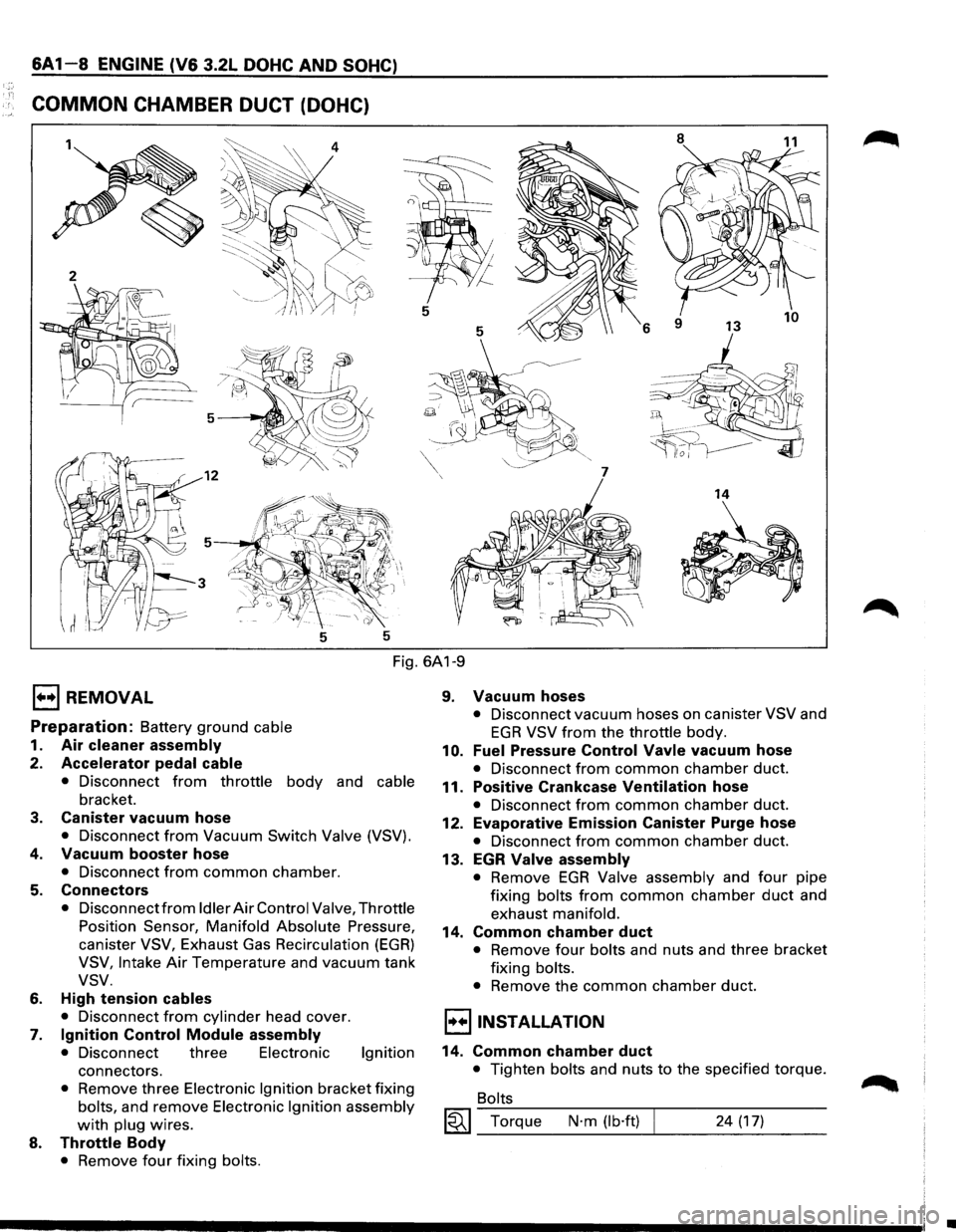
COMMON CHAMBER DUCT (DOHC)
8
11
5
5
6
7
14
5 5
Fig. 6A1-9
E) REMOVAL
Preparation: Battery ground cable
1. Air cleaner assembly
2. Accelerator pedal cable
• Disconnect from throttle body and cable
bracket.
3. Canister vacuum hose
• Disconnect from Vacuum Switch Valve (VSV).
4. Vacuum booster hose
• Disconnect from common chamber.
5. Connectors
• Disconnect from Idler Air Control Valve, Throttle
Position Sensor, Manifold Absolute Pressure,
canister VSV, Exhaust Gas Recirculation (EGR)
VSV, Intake Air Temperature and vacuum tank
vsv.
6. High tension cables
• Disconnect from cylinder head cover.
7. Ignition Control Module assembly
• Disconnect three Electronic Ignition
connectors.
• Remove three Electronic Ignition bracket fixing
bolts, and remove Electronic Ignition assembly
with plug wires.
8. Throttle Body
• Remove four fixing bolts.
9. Vacuum hoses
• Disconnect vacuum hoses on canister VSV and
EGR VSV from the throttle body.
10. Fuel Pressure Control Vavle vacuum hose
• Disconnect from common chamber duct.
11. Positive Crankcase Ventilation hose
• Disconnect from common chamber duct.
12. Evaporative Emission Canister Purge hose
• Disconnect from common chamber duct.
13. EGR Valve assembly
• Remove EGR Valve assembly and four pipe
fixing bolts from common chamber duct and
exhaust manifold.
14. Common chamber duct
• Remove four bolts and nuts and three bracket
fixing bolts.
• Remove the common chamber duct.
l·u·IINSTALLATION
14. Common chamber duct
• Tighten bolts and nuts to the specified torque.
Bolts
~~~ Torque N·m (lb·ft) 24 (17)
•
Page 567 of 1928
Nuts
~~~ Torque N·m (lb·ft) 24 (17)
13. Exhaust Gas Recirculation Valve assembly
• Tighten bolts to the specified torque.
Exhaust Gas Recirculation
Valve Side
~~~ Torque N·m (lb·in) I 8 (69)
Exhaust Manifold Side
~~~ Torque N·m (lb·ft) 28 (21)
12. Evaporative Emission Canister Purge hose
11. Positive Crankcase Vantilatlon hose
10. Fuel Pressure Control Valve vacuum hose
8. Throttle body
• Tighten bolts to the specified torque.
~~~ Torque N·m (lb·ft) I 19 (14)
9. Vacuum hose
• Connect vacuum hoses on canister Vacuum
Switching Valve
and Exhaust Gas Recirculation
Vacuum Switching Valve to the throttle body.
7. Ignition Control Module assembly
• Tighten bolts to the specified torque and
connect connector.
~~~ Torque N·m (lb·ft)
6. High tension cables
5. Connectors
• Connect each connector.
4. Vacuum booster hose
3. Canister vacuum hose
2. Accelerator Pedal cable
19 (14)
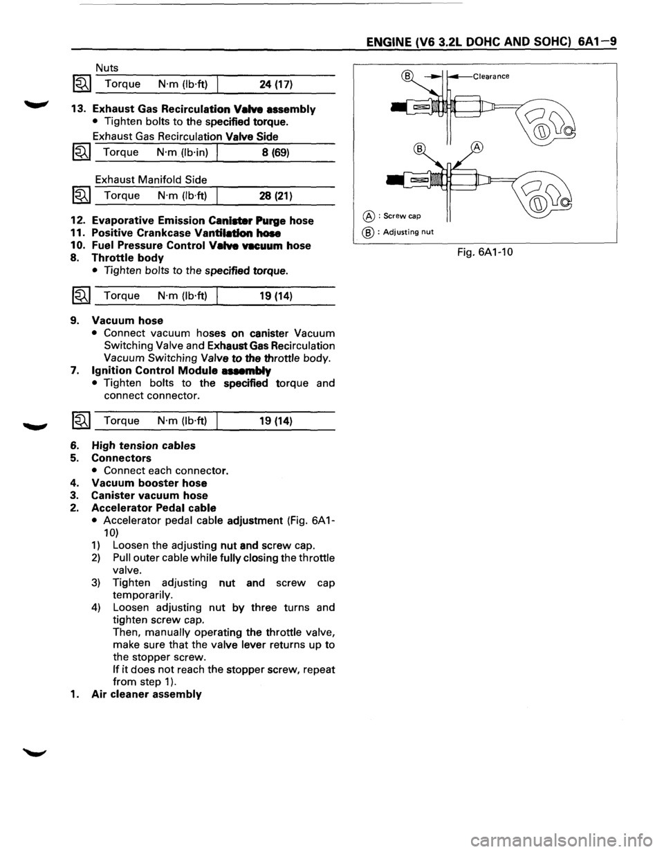
• Accelerator pedal cable adjustment (Fig. 6A 1-
10)
1) Loosen the adjusting nut and screw cap.
2) Pull outer cable while fully closing the throttle
valve.
3) Tighten adjusting nut and screw cap
temporarily.
4) Loosen adjusting nut by three turns and
tighten screw cap.
Then,
manually operating the throttle valve,
make sure that the valve lever returns up to
the stopper screw.
If it does not reach the stopper screw, repeat
from step 1 ).
1. Air cleaner assembly
ENGINE (V6 3.2L DOHC AND SOHC) 6A 1-9
@:Screw cap
@ : Adjusting nut
Fig. 6A1-10
Page 568 of 1928
6A 1 1 0 ENGINE (V6 3.2L DOHC AND SOHC)
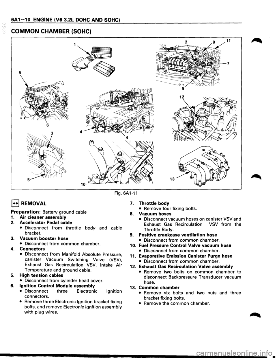
COMMON CHAMBER (SOHC)
5
6
13
Fig. 6A1-11
1••1 REMOVAL
Preparation: Battery ground cable
1. Air cleaner assembly
2. Accelerator Pedal cable
• Disconnect from throttle body and cable
bracket.
3. Vacuum booster hose
• Disconnect from common chamber.
4. Connectors
• Disconnect from Manifold Absolute Pressure,
canister Vacuum Switching
Valve (VSV),
Exhaust Gas Recirculation VSV, Intake Air
Temperature and ground cable.
5. High tension cables
• Disconnect from cylinder head cover.
6. Ignition Control Module assembly
• Disconnect three Electronic Ignition
connectors.
• Remove three Electronic Ignition bracket fixing
bolts, and remove Electronic Ignition assembly
with plug wires.
7. Throttle body
• Remove four fixing bolts.
8. Vacuum hoses
• Disconnect vacuum hoses on canister VSV and
Exhaust Gas
Recirculation VSV from the
Throttle Body.
9. Positive crankcase ventilation hose
• Disconnect from common chamber.
10. Fuel Pressure Control Valve vacuum hose
• Disconnect from common chamber.
11. Evaporative Emission Canister Purge hose
• Disconnect from common chamber.
12. Exhaust Gas Recirculation Valve assembly
• Remove two bolts on common chamber to
disconnect Backpressure Transducer vacuum
hose.
13. Common chamber
• Remove six bolts and two nuts and three
bracket fixing
bolts.
•
Remove the common chamber.
Page 569 of 1928
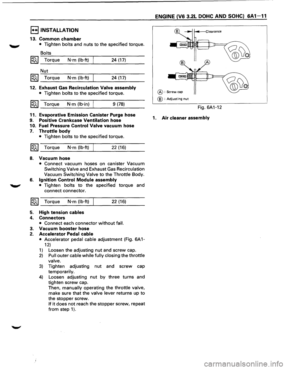
I••IINSTALLATION
13. Common chamber
~ • Tighten bolts and nuts to the specified torque.
~
Bolts
1~1 Torque N·m (lb·ft) 24 (17)
Nut
~~~ Torque N·m (lb·ft) 24 (17)
12. Exhaust Gas Recirculation Valve assembly
• Tighten bolts to the specified torque.
~~~ Torque N·m (lb·in) I 9 (78)
11. Evaporative Emission Canister Purge hose
9. Positive Crankcase Ventilation hose
1
0. Fuel Pressure Control Valve vacuum hose
7. Throttle body
• Tighten bolts to the specified torque.
~~~ Torque N·m (lb·ft) I 22 (16)
8. Vacuum hose
6.
~
5.
4.
3.
2.
• Connect vacuum hoses on canister Vacuum
Switching Valve and Exhaust
Gas Recirculation
Vacuum Switching Valve to the Throttle Body.
Ignition Control Module assembly
• Tighten bolts to the specified torque and
connect connector.
Torque
N·m (lb·ft)
High tension cables
Connectors
22 (16)
• Connect each connector without fail.
Vacuum booster hose
Accelerator Pedal cable
• Accelerator pedal cable adjustment (Fig. 6A 1-
12)
1) Loosen the adjusting nut and screw cap.
2) Pull outer cable while fully closing the throttle
valve.
3) Tighten adjusting nut and screw cap
temporarily.
4) Loosen adjusting nut by three turns and
tighten screw cap.
Then, manually operating the throttle valve,
make sure that the valve lever returns up to
the stopper screw.
If it does not reach the stopper screw, repeat
from step 1 ).
ENGINE (V6 3.2L DOHC AND SOHC) 6A1-11
@:Screw cap
@ :Adjusting nut
Fig. 6A1-12
1. Air cleaner assembly
Page 570 of 1928
1"!
6A 1-12 ENGINE (V6 3.2L DOHC AND SOHC)
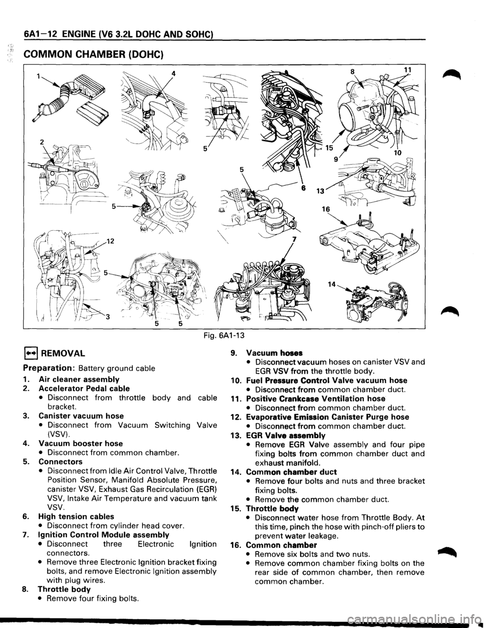
COMMON CHAMBER (DOHC)
Fig. 6A1-13
l•+l REMOVAL
Preparation: Battery ground cable
1. Air cleaner assembly
2. Accelerator Pedal cable
• Disconnect from throttle body and cable
bracket.
3. Canister vacuum hose
• Disconnect from Vacuum Switching Valve
(VSV).
4.
Vacuum booster hose
• Disconnect from common chamber.
5. Connectors
• Disconnect from Idle Air Control Valve, Throttle
Position Sensor, Manifold Absolute Pressure,
canister VSV, Exhaust Gas Recirculation (EGR)
VSV, Intake Air Temperature and vacuum tank
vsv.
6. High tension cables
•
Disconnect from cylinder head cover.
7. Ignition Control Module assembly
• Disconnect three Electronic Ignition
connectors.
• Remove three Electronic Ignition bracket fixing
bolts, and remove Electronic Ignition assembly
with plug wires.
8. Throttle body
• Remove four fixing bolts.
9. Vacuum hoses
• Disconnect vacuum hoses on canister VSV and
EGR VSV from the throttle body.
10. Fuel Pressure Control Valve vacuum hose
• Disconnect from common chamber duct.
11.
Positive Crankcase Ventilation hose
• Disconnect from common chamber duct.
12.
Evaporative Emission Canister Purge hose
• Disconnect from common chamber duct.
13.
EGR Valve assembly
• Remove EGA Valve assembly and four pipe
fixing
bolts from common chamber duct and
exhaust
manifold.
14. Common chamber duct
• Remove four bolts and nuts and three bracket
fixing
bolts.
•
Remove the common chamber duct.
15.
Throttle body
• Disconnect water hose from Throttle Body. At
this time, pinch the hose with pinch-off pliers to
prevent water leakage.
16. Common chamber
• Remove six bolts and two nuts. ~
• Remove common chamber fixing bolts on the
rear side
of common chamber, then remove
common chamber.
1111