automatic transmission ISUZU TROOPER 1995 Repair Manual
[x] Cancel search | Manufacturer: ISUZU, Model Year: 1995, Model line: TROOPER, Model: ISUZU TROOPER 1995Pages: 1928
Page 916 of 1928
7A-44 AUTOMATIC TRANSMISSION (4l30-E)
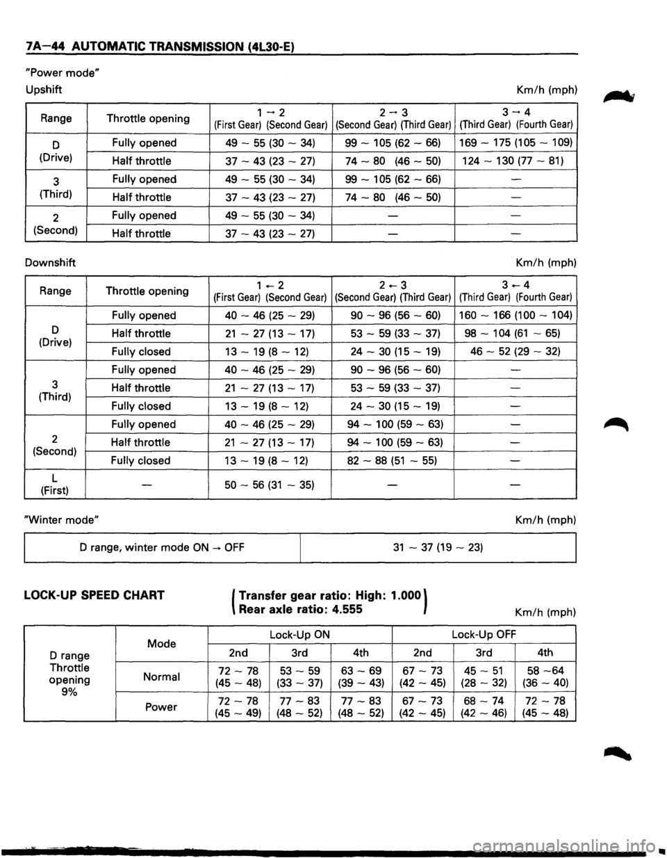
"Power mode"
Upshift Km/h (mph)
Range
Throttle opening 1-2 2-3 3-4
(First Gear) (Second Gear) (Second Gear) (Third Gear) (Third Gear) (Fourth Gear)
D Fully opened 49 -55 (30 -34) 99-105 (62-66) 169-175 (105-109)
(Drive) Half throttle 37 -43 (23 -27) 74-80 (46-50) 124-130 (77-81)
3 Fully opened
49 -55 (30 -34) 99-105 (62-66) -
(Third) Half throttle 37 -43 (23 -27) 74-80 (46-50) -
2 Fully opened
49 -55 (30 -34) --
(Second) Half throttle 37 -43 (23 -27) - -
Downshift Km/h (mph)
Range
Throttle opening 1 +--2 2.-3 3---4
(First Gear) (Second Gear) (Second Gear) (Third Gear) (Third Gear) (Fourth Gear)
Fully opened 40
-46 (25 -29) 90 -96 (56 -60) 160-166 (100-104)
D Half throttle 21 -27 (13 -17) 53 -59 (33 -37) 98-104 (61 -65) (Drive) Fully closed 13 -19 (8 -12) 24 -30 (15 -19) 46 -52 (29 -32)
Fully opened 40
-46 (25 -29) 90 -96 (56 -60) -
3 Half throttle 21 -27 (13 -17) 53 -59 (33 -37) -(Third) Fully closed 13 -19 (8 -12) 24 -30 (15 -19) -
Fully opened 40 -46 (25 -29) 94-100 (59-63) -
2 Half throttle 21 -27 (13 -17) 94-100 (59-63) -(Second) Fully closed 13 -19 (8 -12) 82 -88 (51 -55) -
L 50 -56 (31 -35) (First) -
--
"Winter
mode" Km/h (mph)
D range,
winter mode ON -+ OFF 31 -37 (19-23)
LOCK-UP SPEED CHART
Mode
D range
Throttle
opening Normal
9%
Power
(Transfer
gear ratio: High: 1.000)
Rear axle ratio: 4.555
Lock-Up ON
2nd 3rd 4th 2nd
72-78 53 -59 63-69 67-73
(45-48) (33-37) (39-43) (42-45)
72-78 77-83 77-83 67-73
(45-49) (48-52) (48-52) (42-45)
Km/h (mph)
Lock-Up
OFF
3rd 4th
45-51 58-64
(28-32) (36-40)
68-74 72-78
(42-46) (45-48)
..
Page 917 of 1928
ELECTRONIC DIAGNOSIS
HOW TO DIAGNOSE THE PROBLEM
~ 1. To avoid incorrect diagnostics: this book needs
to be followed accurately. Unless stated: do
not jump
directly to a section that could
contain the solution: some important
information may be missed.
2. The sections in CAPITALS and bold are the
main sections that can be found in the
contents.
3. The GOTO "SECTION" means to continue to
check going to the "section".
4. The GOTHROUGH "SECTION" means to go
through the "section" and then to go back to
the place the GOTHROUGH was written.
5. BASIC ELECTRIC CIRCUITS:
You should understand the basic theory of
electricity. This will include the meaning of
voltage, amps, ohms, and what happens in a
circuit with an open or shorted wire. You
should also be able to read and understand
wiring diagrams.
6. IGNITION CYCLE:
When the car is driven a malfunction can occur
due to a car wiring harness problem, in this
case the driver can reset the system (as on a
personal computer). To reset the computer he
must: (
1) Stop the car and the engine.
(2) Turn the key ignition OFF.
(3) Turn the key ignition ON.
AUTOMATIC TRANSMISSION (4L30·E) 7 A-45
Page 918 of 1928
1 A-46 AUTOMATIC TRANSMISSION (4l30-E)
CHECK TRANS INDICATOR
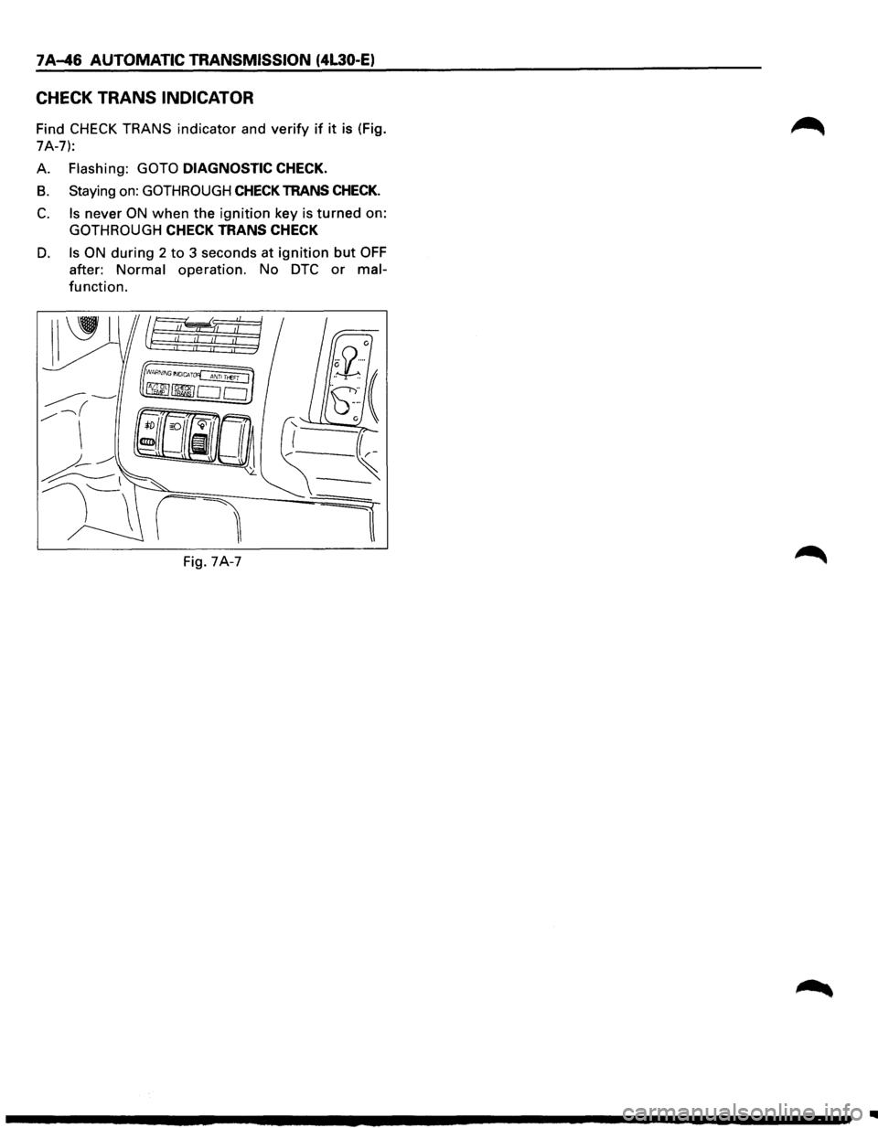
Find CHECK TRANS indicator and verify if it is (Fig.
7A-7):
A.
Flashing: GOTO DIAGNOSTIC CHECK.
B. Staying on: GOTHROUGH CHECK TRANS CHECK.
C. Is never ON when the ignition key is turned on:
GOTHROUGH CHECK TRANS CHECK
D. Is ON during 2 to 3 seconds at ignition but OFF
after: Normal operation. No DTC or mal
function.
Fig. 7A-7
..
Page 919 of 1928
DIAGNOSTIC CHECK
This test determines if the transmission itself or its
~ inputs or outputs connections or sensors are failing.
IF you have a scan tool TECH1:
NO: Use the CHECK TRANS Indicator diagnostic
codes
GOTO FLASHING CODES.
YES:
1. Connect the TECH1: GOTHROUGH TECH1
CONNECTION.
2. Turn on the ignition but not the engine.
3. Push "F2" on TECH1 to see the Diagnostic
Trouble Code (OTC):
4. IF you have DTC?
YES: write down all code numbers and do the
DTCCHECK
NO: the DTC can not help you finding the
problem.
(1) GOTHROUGH "CHECK TRANS" CHECK
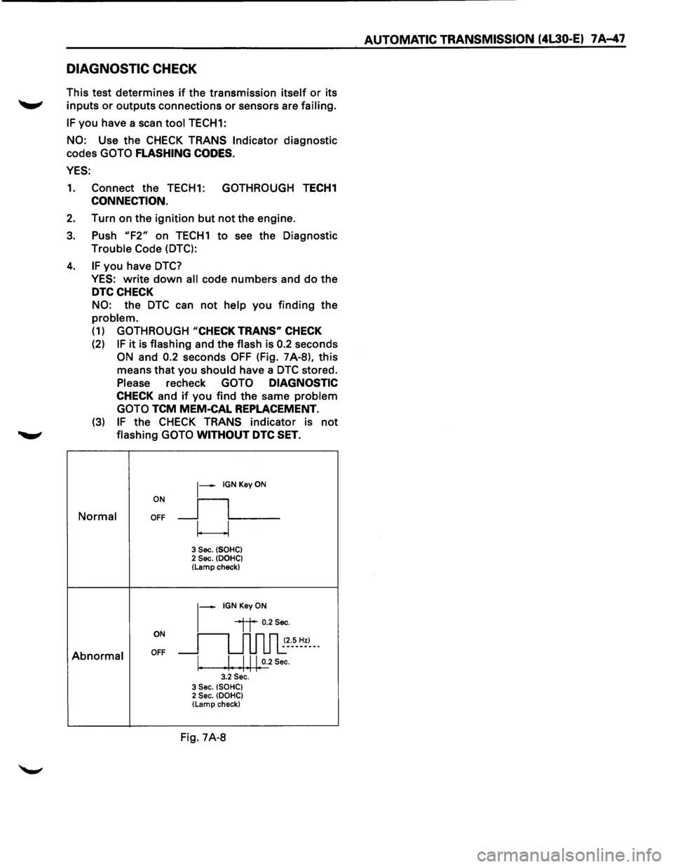
(2) IF it is flashing and the flash is 0.2 seconds
ON and 0.2 seconds OFF (Fig. 7A-8), this
means that you
should have a DTC stored.
Please recheck GOTO DIAGNOSTIC
CHECK and if you find the same problem
GOTO
TCM MEM-CAL REPLACEMENT.
(3) IF the CHECK TRANS indicator is not
........,. flashing GOTO WITHOUT DTC SET.
ON
~-IGNKeyON
__fL__ Normal OFF
w
3 Sec. (SOHC) 2 Sec. (DOHC} (Lamp check)
~-IGNKeyON
ON
~~ 0.2Sec.
~~~5-~=~--
Abnormal OFF
I. I Ill 0.2 Sec. I I I I I 3.2 Sec. 3 Sec. (SOHC) 2 Sec. (DOHC) (Lamp check}
Fig. 7A-8
AUTOMATIC TRANSMISSION (4L30-E) 7 A-47
Page 920 of 1928
7 A-48 AUTOMATIC TRANSMISSION (4L30-E)
"CHECK TRANS" CHECK
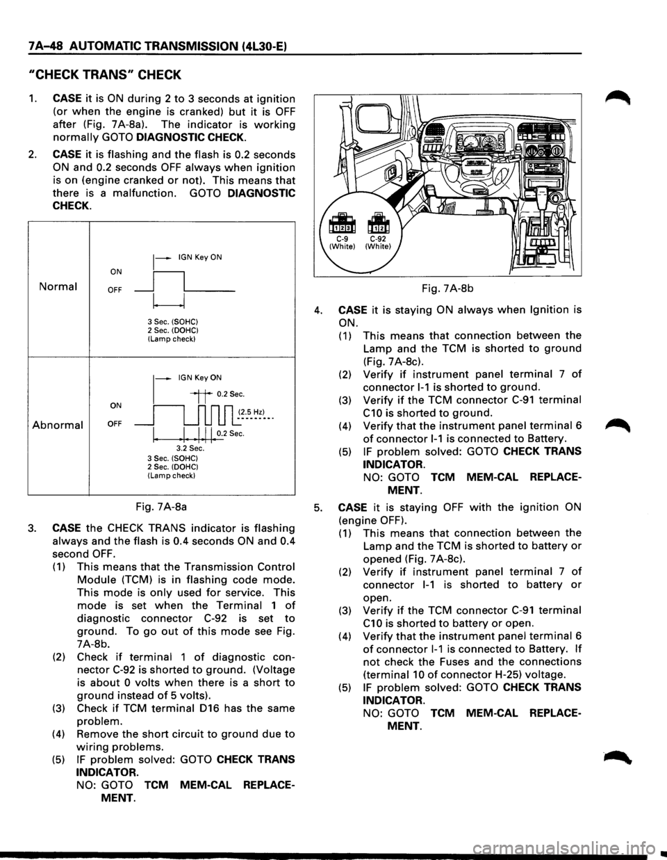
1. CASE it is ON during 2 to 3 seconds at ignition
(or when the engine is cranked) but it is OFF
after (Fig. 7A-8a). The indicator is working
normally GOTO DIAGNOSTIC CHECK.
2. CASE it is flashing and the flash is 0.2 seconds
ON and 0.2 seconds OFF always when ignition
is on (engine cranked or not). This means that
there is a malfunction. GOTO DIAGNOSTIC
CHECK.
Normal
Abnormal
~-IGN Key ON
ON
II
OFF __j l___
~
3 Sec. (SOHC) 2 Sec. (OOHC) (Lamp check)
1-
IGN Key ON
il 0.2Sec.
oN 11 n n n ~~--s_ ~~)-_. OFF __j u u u l:
I. .I. .1.11. 0.2
Sec.
3.2 Sec. 3 Sec. (SOHC) 2 Sec. (OOHC) (Lamp check)
Fig. 7A-8b
4. CASE it is staying ON always when Ignition is
ON.
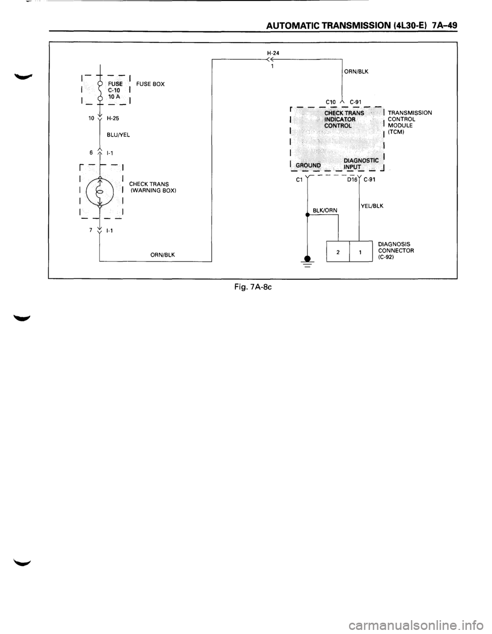
(1) This means that connection between the
Lamp and the TCM is shorted to ground
(Fig. 7 A-8c).
(2) Verify if instrument panel terminal 7 of
connector 1-1 is shorted to ground.
(3) Verify if the TCM connector C-91 terminal
C10 is shorted to ground.
(4) Verify that the instrument panel terminal 6
of connector 1-1 is connected to Battery.
(5) IF problem solved: GOTO CHECK TRANS
INDICATOR.
NO: GOTO TCM MEM-CAL REPLACE
MENT.
Fig. 7A-8a 5. CASE it is staying OFF with the ignition ON
(engine OFF). 3. CASE the CHECK TRANS indicator is flashing
always and the flash is 0.4 seconds ON and 0.4
second OFF.
(1) This means that the Transmission Control
Module (TCM) is in flashing code mode.
This mode is only used for service. This
mode is set when the Terminal 1 of
diagnostic connector C-92 is set to
ground. To go out of this mode see Fig.
7A-8b.
(2) Check
if terminal 1 of diagnostic con
nector C-92 is shorted to ground. (Voltage
is
about 0 volts when there is a short to
ground instead of 5 volts).
(3) Check if TCM terminal 016 has the same
problem.
(4) Remove the short circuit to ground due to
wiring problems.
(5) IF problem solved: GOTO CHECK TRANS
INDICATOR.
NO: GOTO TCM MEM-CAL REPLACE
MENT.
(1) This means that connection between the
Lamp and the TCM is shorted to battery or
opened (Fig. 7 A-8c).
(2) Verify if instrument panel terminal 7 of
connector 1-1 is shorted to battery or
open.
(3)
Verify if the TCM connector C-91 terminal
C1 0 is shorted to battery or open.
(4)
Verify that the instrument panel terminal 6
of connector 1-1 is connected to Battery. If
not check the Fuses and the connections
(terminal 10 of connector H-25) voltage.
(5) IF problem solved: GOTO CHECK TRANS
INDICATOR.
NO: GOTO TCM MEM-CAL REPLACE
MENT.
Page 921 of 1928
FUSE BOX
10 I H-25
BLU!YEL
6 t_l-1
r -~-~
I I CHECK TRANS I I (WARNING BOX)
I I
I
7 1-1
ORN/BLK
AUTOMATIC TRANSMISSION (4l30-E) 7 A-49
H-24
Fig. 7A-8c
ORN/BLK
C10 C-91
f - - -CHiCKTRANS--~ TRANSMISSION I tNOICAfiOR I CONTROL
I CONTROL MODULE I (TCM)
I I
I
I .. DIAGNOSTIC I _GROUNI',): _ _ t~U!_ ..:;;. .J
C1
BLK/ORN
D16 C-91
YEL!BLK
DIAGNOSIS
CONNECTOR
(C-92)
Page 922 of 1928
7 A-50 AUTOMATIC TRANSMISSION (4L30-E)
FLASHING CODES
1. ON BOARD DIAGNOSIS (SELF-DIAGNOSIS)
(1) The Transmission Control Module (TCM)
conducts a
self-test of most of the wiring
and components in the system each time
the key is turned ON. If a fault is detected
the TCM
will store a Diagnostic Trouble
Code (DTC) in memory. It's a number that
corresponds to a specific problem.
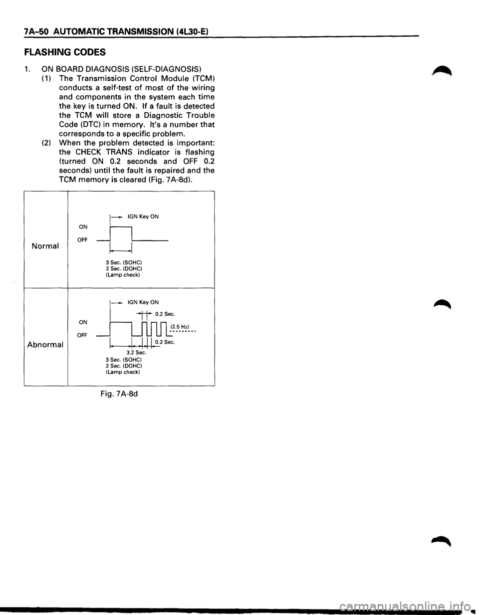
(2) When the problem detected is important:
the
CHECK TRANS indicator is flashing
(turned ON 0.2 seconds and OFF 0.2
seconds) until the fault is repaired and the
TCM
memory is cleared (Fig. 7A-8d).
ON
~--IGN Key ON
_ll___ OFF Normal w
3 Sec. (SOHC) 2 Sec. (DOHC) (Lamp check)
~-IGNKeyON
ON
"it 0.2Sec.
~~--5-~~)--· OFF
Abnormal \. Ill 0.2 Sec. • 1 ••.. 3.2 Sec. 3 Sec. (SOHC) 2 Sec. (DOHC) (Lamp check)
Fig. 7A-8d
Page 923 of 1928
2. DIAGNOSTIC TROUBLE CODES (DTC)
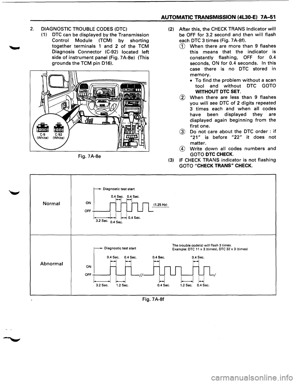
(1) DTC can be displayed by the Transmission
Control Module (TCM) by shorting
together terminals 1 and 2 of the TCM
Diagnosis Connector (C-92)
located left
side of instrument panel (Fig. 7A-8e) (This
grounds the TCM pin D16).
Normal
Abnormal
Fig. 7A-8e
r
Diagnostic test start
0.4 Sec. 0.4 Sec. ~ :..-.! ON I I I I
OFF -----J: : : :
:---f4': -:: ~ 0.4 Sec. 3.2 Sec. 0.4 Sec.
- Diagnostic test start
0.4 Sec. 0.4 Sec.
H H
ONI H H
OFFH H L;;
1*----1 3.2 Sec. 1.2 Sec.
AUTOMATIC TRANSMISSION (4L30-E) 7A-51
(1.25 Hz)
0.4Sec.
' '
' ' ' ' :++l
(2) After this, the CHECK TRANS Indicator will
be OFF for 3.2 second and then will flash
each DTC 3 times (Fig. 7 A-Sf).
CD When there are more than 9 flashes
this means that the indicator is
constantly flashing, OFF for 0.4
seconds, ON for 0.4 seconds. In this
case there is no DTC stored in
memory.
• To find the problem without a scan
tool and without DTC GOTO
WITHOUT DTC SET.
@ When there are less than 9 flashes
you will see DTC of 2 digits repeated
3
times each and when all codes
have been
displayed they are
displayed again beginning from the
first one.
@ Do not care about the DTC order : if
"21" is before "22" it does not
matter.
@ Write down all codes numbers and
GOTO DTC CHECK.
(3) IF CHECK TRANS indicator is not flashing
GOTO
"CHECK TRANS" CHECK.
The trouble code(s) will flash 3 times. Example: DTC 11 x 3 (times), DTC 32 x 3 (times)
0.4 Sec.
' ' I I I I I
1 I I I ~~ 0.4 Sec. 1.2 Sec. 0.4 Sec.
Fig. 7A-8f
Page 924 of 1928
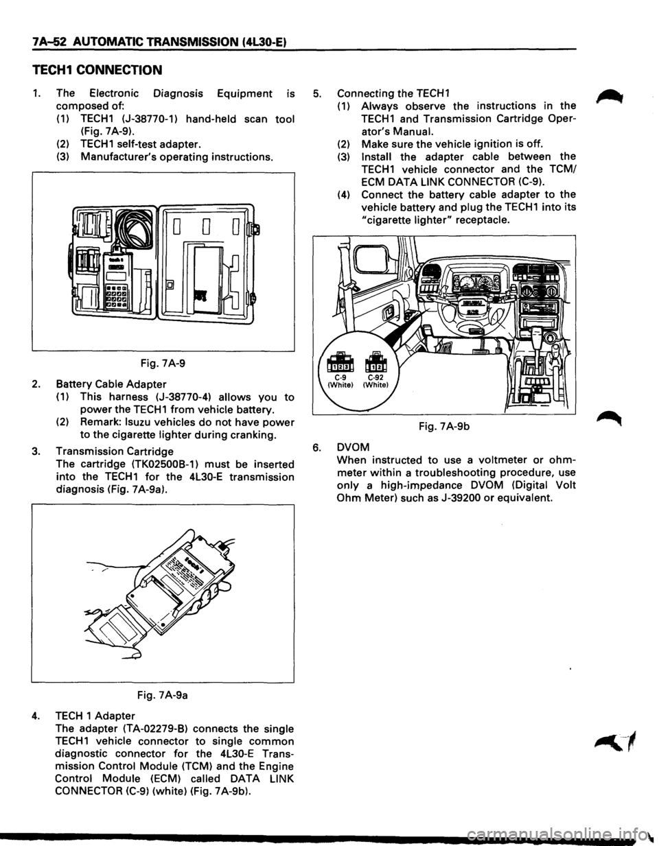
7A..J52 AUTOMATIC TRANSMISSION (4l30-E)
TECH1 CONNECTION
1. The Electronic Diagnosis Equipment is
composed of:
(1) TECH1 (J-38770-1)
hand-held scan tool
(Fig. 7 A-9).
(2)
TECH1 self-test adapter.
(3) Manufacturer's operating instructions.
Fig. 7A-9
2. Battery Cable Adapter
(1) This harness (J-38770-4) allows you to
power the TECH1 from vehicle battery.
(2) Remark:
lsuzu vehicles do not have power
to the cigarette lighter during cranking.
3. Transmission Cartridge
The cartridge
(TK025008-1) must be inserted
into the TECH1 for the 4L30-E transmission
diagnosis (Fig. 7 A-9a).
Fig. 7A-9a
4. TECH 1 Adapter
The adapter
(TA-02279-B) connects the single
TECH1 vehicle connector to single common
diagnostic connector for the 4L30-E Trans
mission
Control Module (TCM) and the Engine
Control Module (ECM) called DATA LINK
CONNECTOR (C-9)
(white) (Fig. 7A-9b).
5. Connecting the TECH1 ~
(1) Always observe the instructions in the
TECH1 and Transmission Cartridge Oper-
ator's
Manual.
(2) Make sure the vehicle ignition is off.
(3) Install the adapter cable between the
TECH1 vehicle connector and the TCM/
ECM
DATA LINK CONNECTOR (C-9).
(4) Connect the battery cable adapter to the
vehicle battery and plug the TECH1 into its
"cigarette lighter" receptacle.
Fig. 7A-9b
6. DVOM
When instructed to use a voltmeter or ohm
meter within a troubleshooting procedure, use
only a high-impedance DVOM (Digital Volt
Ohm
Meter) such as J-39200 or equivalent.
Page 925 of 1928
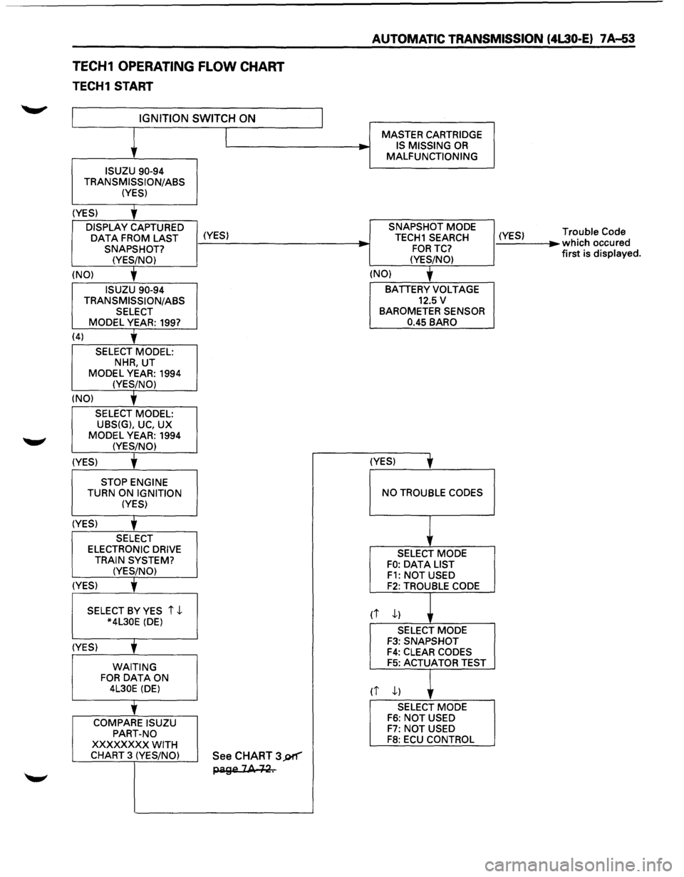
TECH1 OPERATING FLOW CHART
TECH1 START
IGNITION SWITCH ON
ISUZU 90-94
TRANSMISSION/ASS (YES)
(YES)
'
DISPLAY CAPTURED
OAT A FROM LAST (YES) SNAPSHOT?
(YES/NO)
(NO)
'
ISUZU 90-94
TRANSMISSION/ASS SELECT MODEL YEAR: 199?
(4)
'
SELECT MODEL: NHR, UT
MODEL YEAR: 1994 (YES/NO)
(NO)
'
SELECT MODEL: UBS(G), UC, UX
MODEL YEAR: 1994 (YES/NO)
(YES) t
STOP ENGINE TURN ON IGNITION (YES)
(YES)
'
SELECT ELECTRONIC DRIVE
TRAIN SYSTEM? (YES/NO)
(YES)
' SELECT BY YES i ,J.. *4L30E (DE)
(YES)
' WAITING FOR DATA ON 4L30E (DE)
'
COMPARE ISUZU
PART-NO
XXXXXXXX WITH CHART 3 (YES/NO) See CHART 3J)f"'"'"
page 2A +~.
__, -
AUTOMATIC TRANSMISSION (4L30-E) 7 A-53
MASTER CARTRIDGE
IS MISSING OR MALFUNCTIONING
SNAPSHOT MODE
TECH1 SEARCH
FORTC?
(YES/NO)
(NO)
'
BATIERY VOLTAGE 12.5 v BAROMETER SENSOR
0.45 BARO
(YES)
' NO TROUBLE CODES
SELECT MODE FO: OAT A LIST F1: NOT USED F2: TROUBLE CODE
rt ,J..)
SELECT MODE F3: SNAPSHOT F4: CLEAR CODES F5: ACTUATOR TEST
(i ,J..) ,
SELECT MODE F6: NOT USED F7: NOT USED F8: ECU CONTROL
(YES) ...
Trouble Code which occured
first is displayed.