brake ISUZU TROOPER 1995 Manual Online
[x] Cancel search | Manufacturer: ISUZU, Model Year: 1995, Model line: TROOPER, Model: ISUZU TROOPER 1995Pages: 1928
Page 363 of 1928
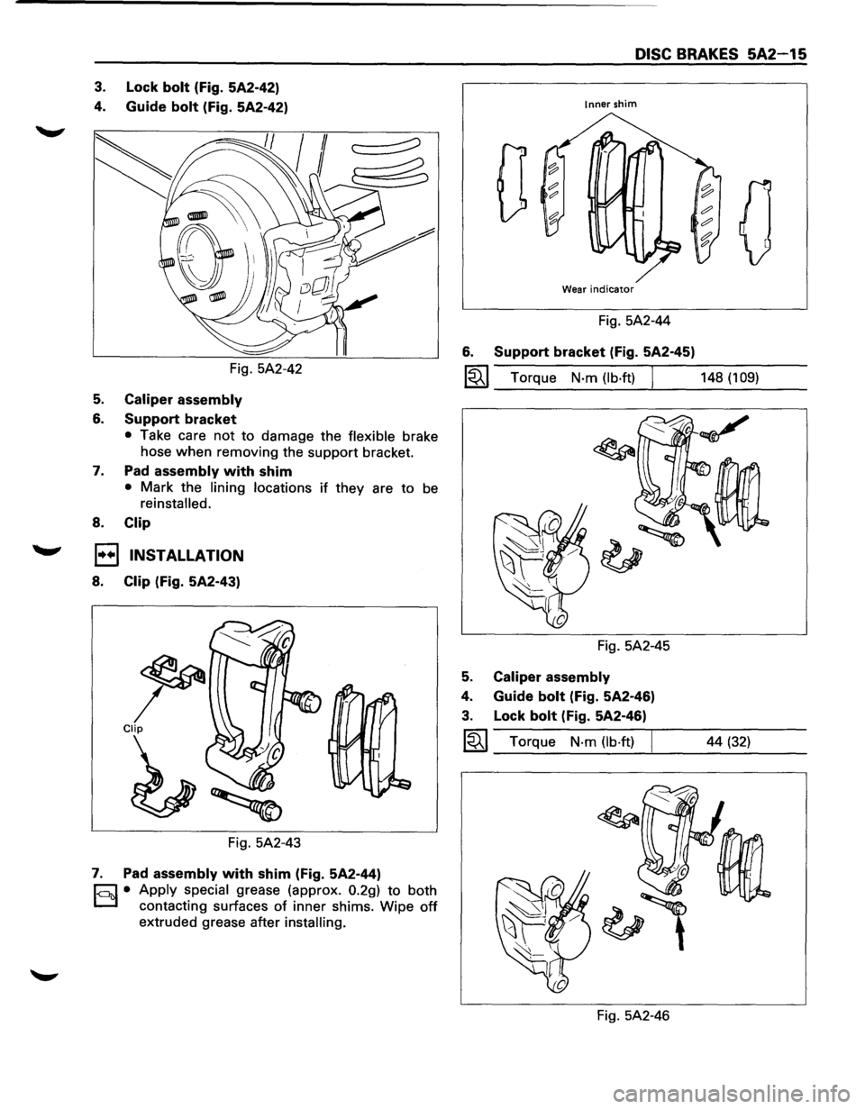
3. Lock bolt (Fig. 5A2-42)
4.
Guide bolt (Fig. 5A2-42)
Fig. 5A2-42
5. Caliper assembly
6. Support bracket
• Take care not to damage the flexible brake
hose
when removing the support bracket.
7. Pad assembly with shim
• Mark the lining locations if they are to be
reinstalled.
8. Clip
1••1 INSTALLATION
8. Clip (Fig. 5A2-43)
Fig. 5A2-43
7. Pad assembly with shim (Fig. 5A2-44)
r;::;:] • Apply special grease (approx. 0.2g) to both
D contacting surfaces of inner shims. Wipe off
extruded grease after installing.
DISC BRAKES 5A2-15
Inner shim
0
Wear indicator
Fig. 5A2-44
6. Support bracket (Fig. 5A2-45)
~~~ Torque N·m (lb·ft) I 148 (109)
Fig. 5A2-45
5. Caliper assembly
4. Guide bolt (Fig. 5A2-46)
3. Lock bolt (Fig. 5A2-46)
~~~ Torque N·m (lb·ft) I
Fig. 5A2-46
44 (32)
Page 364 of 1928
5A2-16 DISC BRAKES
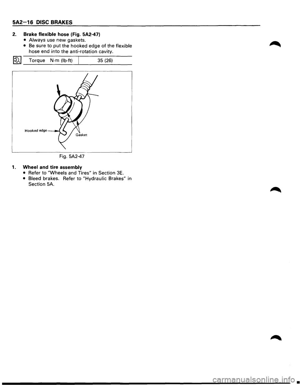
2. Brake flexible hose (Fig. 5A2-47)
• Always use new gaskets.
• Be sure to put the hooked edge of the flexible
hose end into the anti-rotation cavity.
~~~ Torque N-m (lb·ft) 35 (26)
Hooked edge
Fig. 5A2-47
1. Wheel and tire assembly
• Refer to "Wheels and Tires" in Section 3E.
• Bleed brakes. Refer to "Hydraulic Brakes" in
Section 5A.
•
Page 365 of 1928
DISC BRAKES 5A2-17
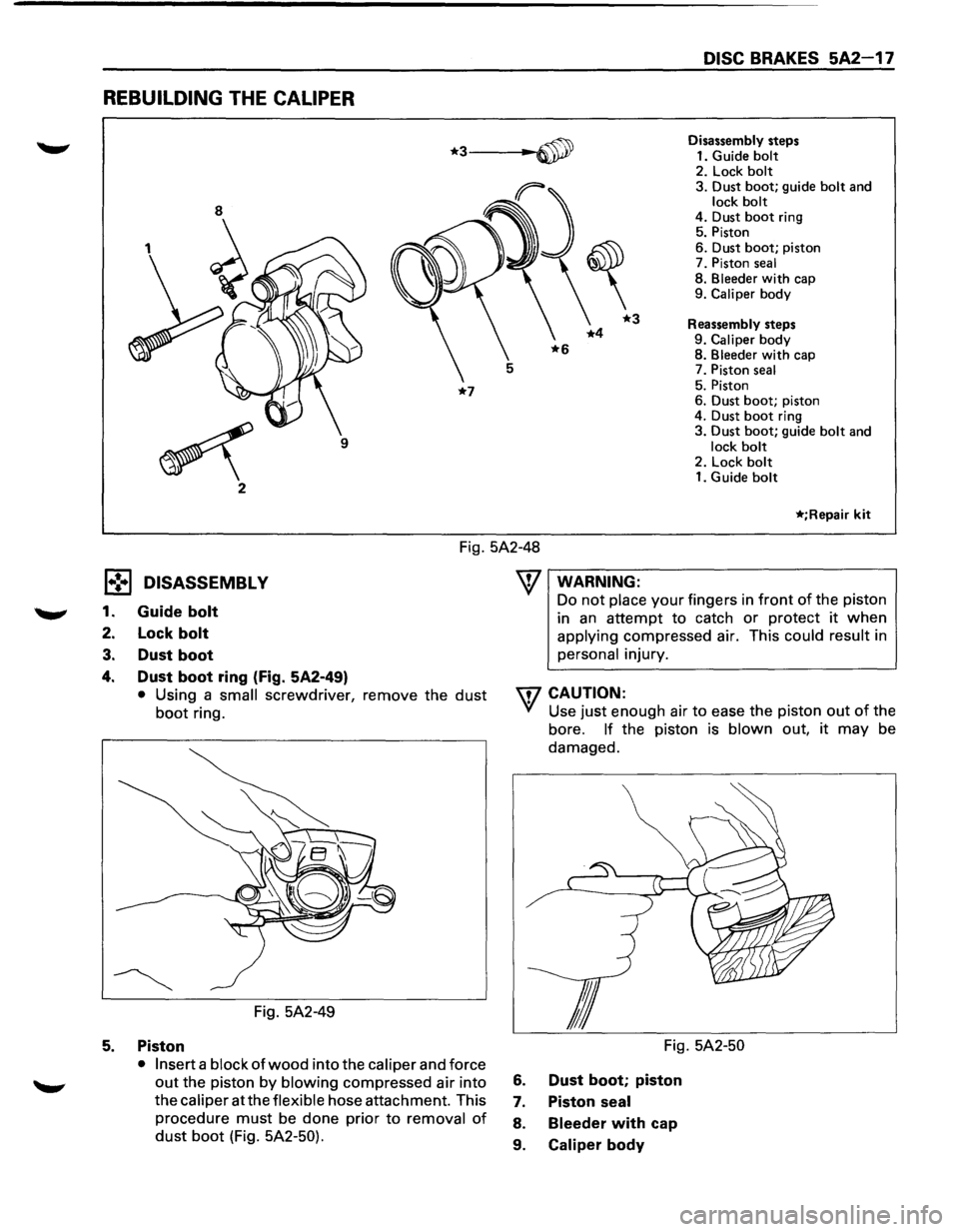
REBUILDING THE CALIPER
*3~ Disassembly steps
1. Guide
bolt
*7
9
2. Lock bolt 3. Dust boot; guide bolt and lock bolt 4. Dust boot ring
5. Piston
6. Dust
boot; piston
7. Piston seal
8. Bleeder with cap
9. Caliper body
Reassembly steps
9.
Caliper body
8. Bleeder with cap
7. Piston seal
5. Piston
6. Dust boot; piston
4. Dust boot ring
3. Dust
boot; guide bolt and lock bolt
2. Lock bolt 1. Guide bolt
*;Repair kit
Fig. 5A2-48
l•!•l DISASSEMBLY
1. Guide bolt
2. Lock bolt
3. Dust boot
4. Dust boot ring (Fig. 5A2-49)
• Using a small screwdriver, remove the dust
boot ring.
Fig. 5A2-49
5. Piston
• Insert a block of wood into the caliper and force
out the piston by blowing compressed air into
the caliper at the
flexible hose attachment. This
procedure
must be done prior to removal of
dust boot (Fig. 5A2-50).
WARNING:
Do not place your fingers in front of the piston
in
an attempt to catch or protect it when
applying compressed air. This could result in
personal injury.
\f7 CAUTION:
VI Use just enough air to ease the piston out of the
bore.
If the piston is blown out, it may be
damaged.
Fig.
5A2-50
6. Dust boot; piston
7. Piston seal
8. Bleeder with cap
9.
Caliper body
Page 366 of 1928
![ISUZU TROOPER 1995 Manual Online 5A2-18 DISC BRAKES
(1!] INSPECTION AND REPAIR
Make necessary parts replacement, if wear, damage,
corrosion
or any other abnormal conditions are found
through inspection.
Check the
followi](/img/61/57183/w960_57183-365.png "ISUZU TROOPER 1995 Manual Online 5A2-18 DISC BRAKES
(1!] INSPECTION AND REPAIR
Make necessary parts replacement, if wear, damage,
corrosion
or any other abnormal conditions are found
through inspection.
Check the
followi")
5A2-18 DISC BRAKES
(1!] INSPECTION AND REPAIR
Make necessary parts replacement, if wear, damage,
corrosion
or any other abnormal conditions are found
through inspection.
Check the
following parts;
• Rotor
• Cylinder body
• Cylinder bore
• Piston
• Slide
pin
• Support bracket
NOTE:
The piston dust seal and dust boot are to be replaced
each time the caliper is overhauled. Discard these
used rubber parts and
replace with new ones.
1•! .. 1 REASSEMBLY
9. Caliper body
8. Bleeder with cap
1~1 Torque N·m (lb·in) 8 (69)
7. Piston seal (Fig. 5A2-51)
r:::;] • Apply special rubber grease to the piston seal
D and cylinder wall, then insert the piston seal
into the cylinder. The special rubber grease is
included in the repair kit.
Fig. 5A2-51
5. Piston
6. Dust boot; piston (Fig. 5A2-52)
• When inserting the piston into the cylinder, use
finger pressure
only. Do not use a mallet or
other impact tools, since damage to the
cylinder wall or piston seal can result.
4. Dust boot ring (Fig. 5A2-53)
r:::;] • Apply special grease (Approx. 1 g) to the piston
D and attach the dust boot to the piston and
caliper. Insert the dust boot ring into the dust
boot. Fig.
5A2-52
Fig. 5A2-53
3. Dust boot (Fig. 5A2-54)
r:::;] • Install the dust boot on the support bracket
D after applying special grease (Approx. 1 g) onto
the dust
boot inner surface. Also apply special
grease onto the lock bolt and guide bolt setting
hole of the support bracket.
2. Lock bolt
1. Guide bolt
Fig. 5A2-54
~~~ Torque N-m (lb·ft) 44 (32)
•
Page 367 of 1928
DISC BRAKES 5A2-19
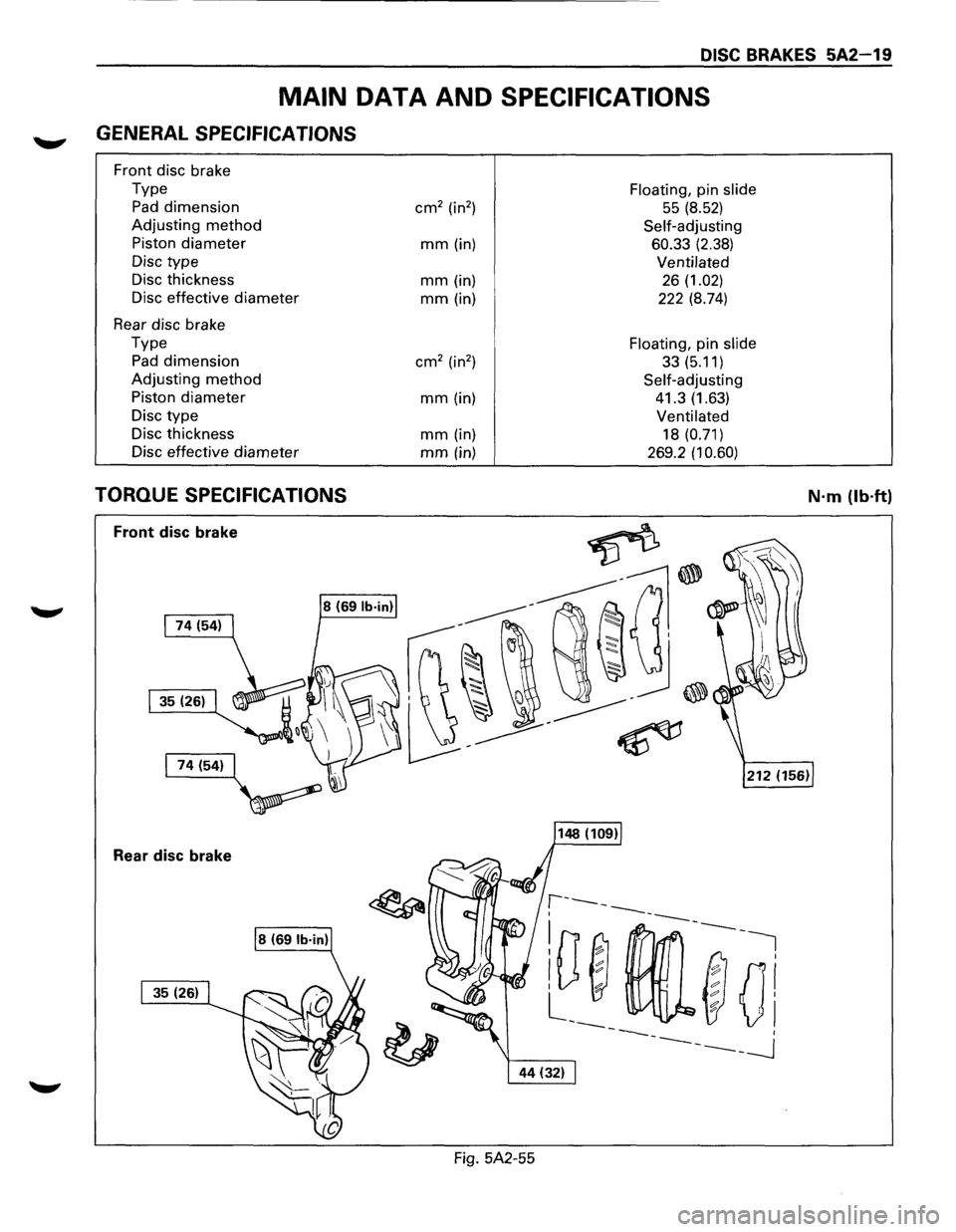
MAIN DATA AND SPECIFICATIONS
~ GENERAL SPECIFICATIONS
Front disc brake
Type
Floating, pin slide
Pad dimension cm2 (in2 ) 55 (8.52)
Adjusting method Self-adjusting
Piston
diameter mm (in) 60.33 (2.38)
Disc type Ventilated
Disc thickness mm (in) 26 (1.02)
Disc effective diameter
mm(in) 222 (8.74)
Rear disc brake
Type
Floating, pin slide
Pad dimension cm2 (in2
) 33(5.11)
Adjusting
method Self-adjusting
Piston
diameter mm (in) 41.3 (1.63)
Disc
type Ventilated
Disc thickness mm (in) 18 (0.71)
Disc effective
diameter mm (in) 269.2 (1 0.60)
TORQUE SPECIFICATIONS N·m (lb·ft)
Front disc brake
Rear disc brake
Fig. 5A2-55
Page 369 of 1928
REAR WHEEL ANTILOCK BRAKE SYSTEM 5A3-1
SECTION 5A3
REAR WHEEL ANTILOCK BRAKE SYSTEM
(RWAL}
w CAUTION:
• All brake attaching fasteners are an important attaching part in that they could affect performance of vital
parts and systems, and/or could result in major repair expense. They must be replaced with one of the same
part
number or with an equivalent part if replacement becomes necessary. Do not use replacement parts of
lesser quality or substitute design. Torque values must be used as specified during reassembly to assure
proper retention of these parts.
CONTENTS
Introduction . . . . . . . . . . . . . . . . . . . . . . . . . 5A3· 1
General Description . .
. . . . . . . . . . . . . . .
5A3· 1
Rear
Wheel Antilock (RWAL) Control
Parts Location . .
. . . . . . . . . . . . . . . . .
5A3· 5
System Diagram . .
. . . . . . . . . . . . . . . . . . . .
5A3· 6
Rear
Wheel Antilock (RWAL) System
Diagnostics . .
. . . . . . . . . . . . . . . . . . . . . .
5A3· 7
On-Vehicle Service . .
. . . . . . . . . . . . . . . . .
5A3·38
RWAL Electronic Brake Control
Module (EBCM) Replacement ....... 5A3-38
Antilock
(Isolation/Dump) Valve
Replacement ..................... 5A3-39
Speed Sensor Replacement
.......... 5A3-40
Main Data and Specifications ........... 5A3-41
Torque Specifications
............... 5A3-41
INTRODUCTION
This section deals with the complete diagnosis and
services
for vehicles equipped with rear wheel
antilock.
For service information regarding all other
components
of the brake system, refer to "Hydraulic
Brakes"
(Sec. SA), "Brake Booster System" (Sec. SA 1)
or "Disc Brakes" (Sec. SA2) of this Manual.
GENERAL DESCRIPTION
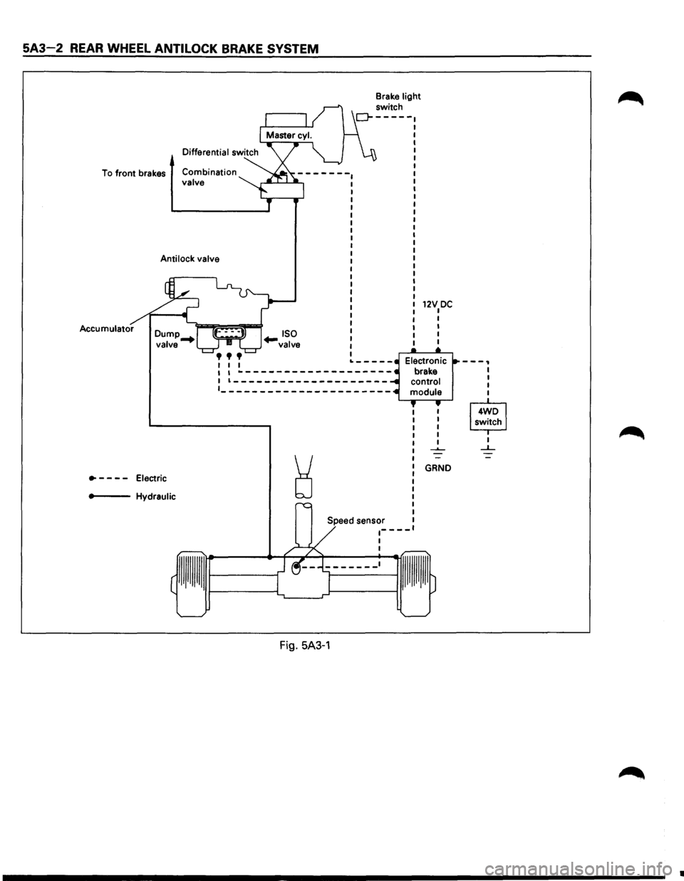
The rear wheel anti lock system (RWAL) is designed to
reduce rear wheel lock-up during a severe brake
application,
thus maintaining rear end stability. The
system functions
by regulating the rear hydraulic
brake line pressure. The pressure regulation is
accomplished
by an anti lock valve which is located on
the
front right side of engine room. The anti lock valve
is made up of two valves, a dump valve which releases
pressure into an accumulator and an isolation valve
which maintains rear brake pressure. The valve is
controlled
by a microcomputer which is part of the
Electronic Brake Control Module (EBCM). The
EBCM is mounted at the
front of the center
console. Under severe brake application, as pressure
is
applied to the brake pedal, the EBCM is designed to
permit the valve to do one of three functions or a
combination
of all three. The EBCM will allow the valve
to either maintain the same amount of hydraulic
pressure, release hydraulic pressure through the
dump valve into the accumulator or increase the
pressure by
pulsing the isolation valve.
The EBCM operates by receiving signals from the
speed sensor (which
is located in the differential
carrier), combination
valve and the brake light switch.
The RWAL system is connected
to the RWAL indicator
light located on the dash. An indication of the RWAL
operation and a
bulb check is performed each time the
ignition is turned
"ON". The indicator light will remain
on
for about two seconds. A RWAL system
malfunction is indicated if the RWAL indicator light
stays on, or comes on during driving. To determine the
specific
trouble, refer to "RWAL System Diagnostics"
in this section.
Page 370 of 1928
5A3-2 REAR WHEEL ANTILOCK BRAKE SYSTEM
To front brakes Combination valve
Anti lock valve
Accumulator
•
- -
- -
Electric
.,_ __ Hydraulic
I I I I I ~-------------------1 1--------------------
1_---------------------
Speed sensor
~----1 I
Fig. 5A3-1
12V DC I I
I
I
I
GRND
---, I I I
I
I
--'--
•
Page 371 of 1928
REAR WHEEL ANTILOCK BRAKE SYSTEM 5A3-3
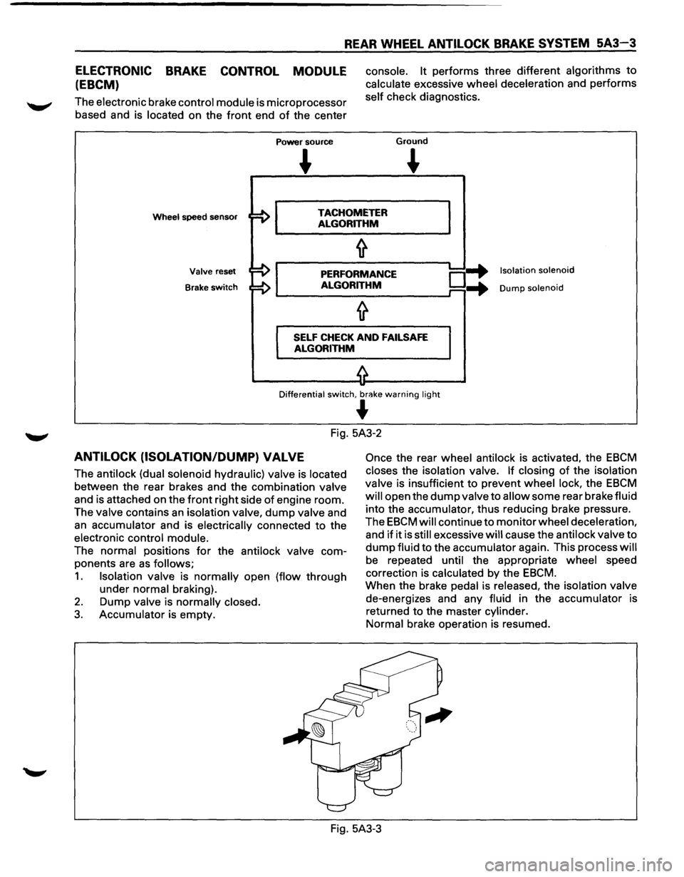
ELECTRONIC BRAKE CONTROL MODULE
(EBCM)
The electronic brake control module is microprocessor
based and is located on the
front end of the center
Power source
console. It performs three different algorithms to
calculate excessive wheel deceleration and performs
self check diagnostics.
Ground
~
Wheel speed sensor TACHOMETER
ALGORITHM
Valve reset
Brake
switch
PERFORMANCE
ALGORITHM o-+ ...
Isolation solenoid
Dump solenoid
SELF CHECK AND FAILSAFE
ALGORITHM
Differential switch, br<'!ke warning light
~
Fig. 5A3-2
ANTILOCK (ISOLATION/DUMP) VALVE
The antilock (dual solenoid hydraulic) valve is located
between the rear brakes and the combination valve
and is attached on the
front right side of engine room.
The valve contains
an isolation valve, dump valve and
an accumulator and is electrically connected to the
electronic control module.
The normal positions
for the antilock valve com
ponents are
as follows;
1. Isolation valve is normally open (flow through
under normal braking).
2. Dump valve is normally closed.
3. Accumulator is empty.
Once the rear wheel antilock is activated, the EBCM
closes the isolation valve. If closing of the isolation
valve is insufficient to prevent wheel lock, the
EBCM
will open the dump valve to allow some rear brake fluid
into the accumulator, thus reducing brake pressure.
The
EBCM will continue to monitor wheel deceleration,
and
if it is still excessive will cause the antilock valve to
dump fluid to the accumulator again. This process will
be repeated until the appropriate wheel speed
correction is calculated by the
EBCM.
When the brake pedal is released, the isolation valve
de-energizes and any fluid in the accumulator is
returned to the master cylinder.
Normal brake operation is resumed.
Fig. 5A3-3
Page 372 of 1928
5A3-4 REAR WHEEL ANTILOCK BRAKE SYSTEM
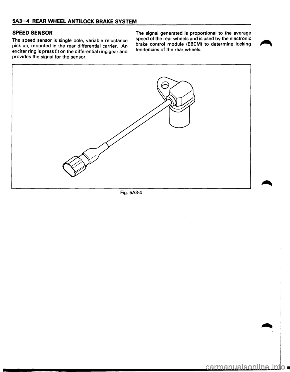
SPEED SENSOR
The speed sensor is single pole, variable reluctance
pick up, mounted
in the rear differential carrier. An
exciter ring
is press fit on the differential ring gear and
provides the signal for the sensor. The
signal generated is proportional
to the average
speed
of the rear wheels and is used by the electronic
brake control module
(EBCM) to determine locking
tendencies
of the rear wheels.
Fig. 5A3-4
•
Page 373 of 1928
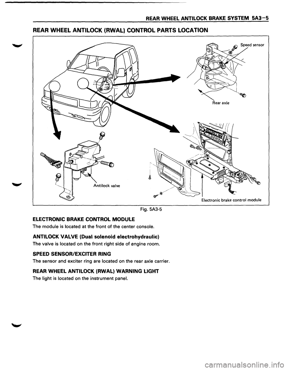
REAR WHEEL ANTILOCK BRAKE SYSTEM 5A3-5
REAR WHEEL ANTILOCK (RWAL} CONTROL PARTS LOCATION
Fig. 5A3-5
ELECTRONIC BRAKE CONTROL MODULE
The module is located at the front of the center console.
ANTILOCK VALVE (Dual solenoid electrohydraulic)
The valve is located on the front right side of engine room.
SPEED SENSOR/EXCITER RING
The sensor and exciter ring are located on the rear axle carrier.
REAR WHEEL ANTILOCK (RWAL) WARNING LIGHT
The light is located on the instrument panel.
Rear axle
Electronic
brake control module