transmission ISUZU TROOPER 1995 Manual Online
[x] Cancel search | Manufacturer: ISUZU, Model Year: 1995, Model line: TROOPER, Model: ISUZU TROOPER 1995Pages: 1928
Page 878 of 1928
7A-6 AUTOMATIC TRANSMISSION (4L30-E)
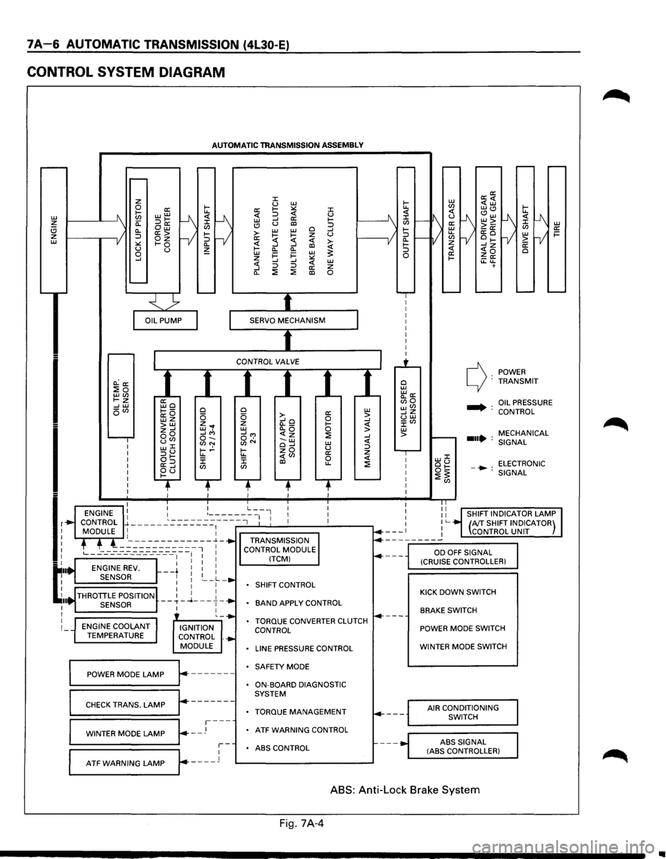
CONTROL SYSTEM DIAGRAM
L1J ~ (!) z L1J
I
I
lr
t:··
~ .. I I
I
I
AUTOMATIC TRANSMISSION ASSEMBLY
O.:a: :Eo LLJ(J) t-z --' L1J oVl
ENGINE COOLANT TEMPERATURE
ffio ~---a:O wz >LLJ z--' oo uCJ> w::C :::>u at-a:=> ~d
0 0 z ... w, --'"' o-.. (J)N t-.!-u.. J: CJ)
IGNITION
CONTROL .
MODULE
~==PO=W==ER==M=O=D=E=L=A=M=P~r.-------
r-------CHECK TRANS. LAMP
~=W=IN=T=E=R=M=O=D=E=LA=M=P~~--J---
::c u L1J a: 1-:.:: ::c <( :::> <( u L1J --' a: 1-(!) u al :::> >-L1J L1J 0 --' 1-~ z u a: :5 <( ~ ~ --' al Cl.
Cl. L1J i=
i= L1J ~ z :.:: --' --' <( L1J :5 :::> :::> a: z Cl. ::!: ::!: al 0
0 a: L1J 0 >-0 > --'o --' z (l._ 1-<( L1J Cl.Q 0 > __,...,
SHIFT
CONTROL
BAND APPLY CONTROL
TORQUE CONVERTER CLUTCH CONTROL
LINE PRESSURE CONTROL
SAFETY MODE
ON-BOARD DIAGNOSTIC
SYSTEM
TORQUE MANAGEMENT
ATF WARNING CONTROL
r-ABS CONTROL
L--A-T_F_w_A_R_N_I_N_G_L_A_M_P_...Jr---_l 1---------------'
0 L1J "'a: Bio wVl __,z uw J:Vl L1J >
POWER c): TRANSMIT
.... : OIL PRESSURE
CONTROL
MECHANICAL
...• : SIGNAL
LLJJ: ou ELECTRONIC ot:: -•: ::!:~ SIGNAL
KICK DOWN SWITCH
BRAKE SWITCH
POWER MODE SWITCH
WINTER MODE SWITCH
AIR CONDITIONING
SWITCH
ABS
SIGNAL (ASS CONTROLLER)
ABS: Anti-Lock Brake System
Fig. 7A-4
..
Page 879 of 1928
1. SHIFT CONTROL
The transmission gear is shifted according to the
shift pattern selected by the driver.
~ In shifting gears, the gear ratio is controlled by the
ON/ OFF signal using the 1-2/3-4 shift solenoids and
the 2-3 shift solenoid.
2. BAND APPLY CONTROL
The band apply is controlled when in the 3-2
downshift (engine overrun prevention) and the
garage shift (shock control).
The band
apply solenoid is controlled by the signal
from the Pulse Width Modulation (PWM) to regulate
the
flow of the oil.
3. TORQUE CONVERTER CLUTCH CONTROL
The clutch ON/OFF is controlled by moving the
converter clutch valve through shifting Torque
Converter Clutch
(TCC) solenoid using the ON/OFF
signal.
4. LINE PRESSURE CONTROL
The throttle signal allows the current signal to be
sent
to the force motor. After receiving the current
signal, the force motor activates the pressure
regulator valve to regulate the line pressure.
5. ON-BOARD DIAGNOSTIC SYSTEM
Several malfunction displays can be stored in the
Transmission Control Module (TCM) memory, and
read
out of it afterward.
The serial data lines, which are required for the
testing of the final assembly and the coupling to
other electronic modules, can be regulated by this
function.
6 FAIL-SAFE MECHANISM
If there is a problem in the transmission system, the
TCM will go into a "backup" mode. The vehicle can
still be driven, but the driver must use the gear
lever to shift gears.
7. TORQUE MANAGEMENT CONTROL
The TCM sends the absolute spark advance signal
to the Engine Control Module (ECM) while the
transmission is being shifted, to control the engine
spark timing in compliance with the vehicle running
condition to reduce the shocks caused by the
change of speed.
8. ATF WARNING CONTROL
The oil temperature sensor detects the ATF oil
temperature to control the oil temperature warning,
TCC and the winter mode.
9. ABS CONTROL
When the select lever is at "L" or "R" range, a
signal is sent
to the ABS controller as one of the
ABS control conditions.
AUTOMATIC TRANSMISSION (4L30-E) 7A-7
Page 880 of 1928
7 A-8 AUTOMATIC TRANSMISSION (4l30-E)
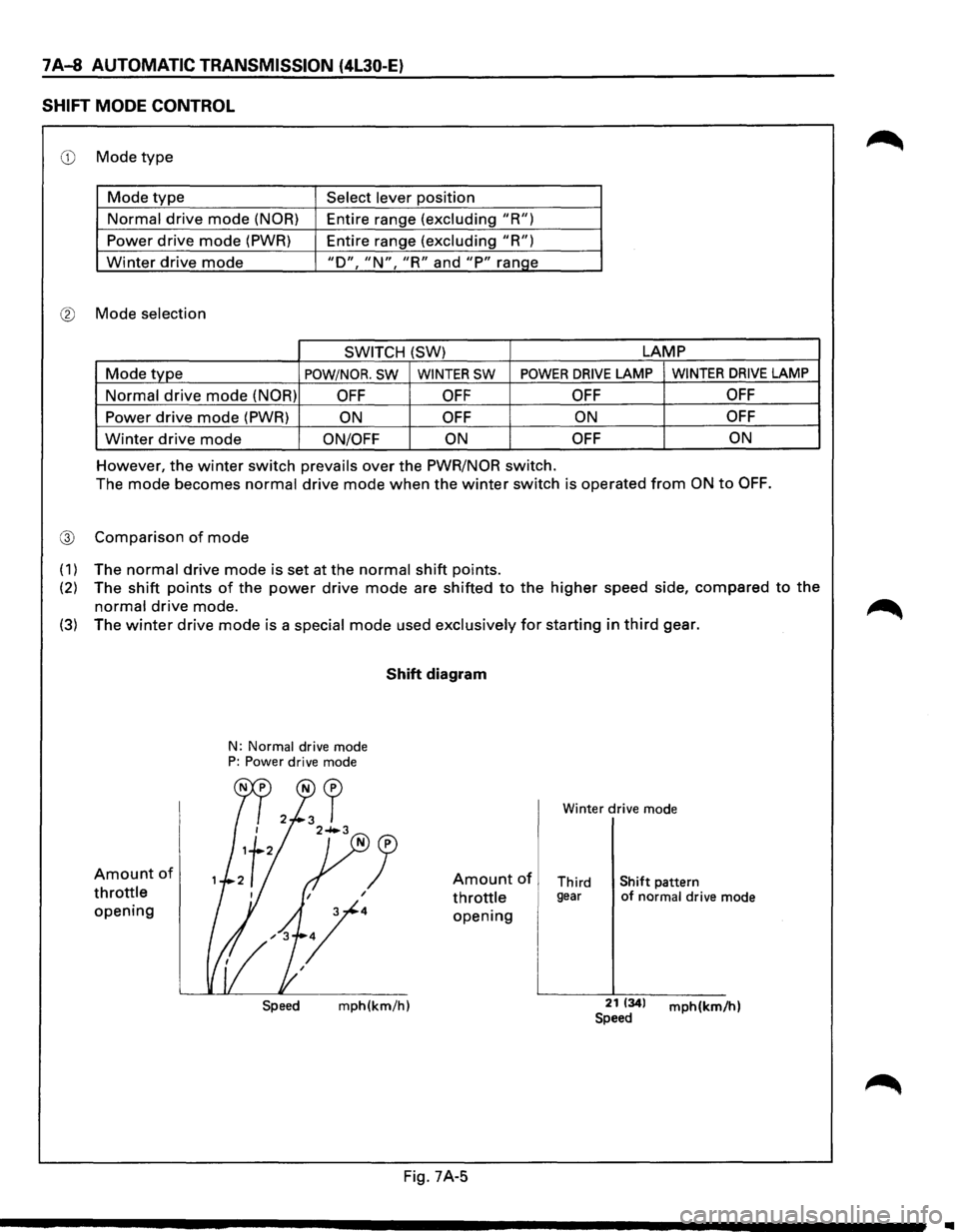
SHIFT MODE CONTROL
CD Mode type
Mode type Select lever position
Normal drive mode (NOR) Entire range (excluding "R")
Power drive mode (PWR) Entire range (excluding "R")
Winter drive mode "D", "N", "R" and "P" range
® Mode selection
SWITCH
(SW) LAMP
Mode type POW/NOR. SW WINTER SW POWER DRIVE LAMP WINTER DRIVE LAMP
Normal drive mode (NOR) OFF OFF
OFF OFF
Power drive mode (PWR) ON OFF ON OFF
Winter drive mode ON/OFF
ON OFF ON
However, the winter switch prevails over
the PWR/NOR switch.
The
mode becomes normal drive mode when the winter switch is operated from ON to OFF.
@ Comparison of mode
(1) The normal drive mode is set at the normal shift points.
(2) The shift points of the power drive mode are shifted to the higher speed side, compared to the
normal drive mode.
(3) The winter drive mode is a special mode used exclusively for starting in third gear.
Amount of
throttle
opening
N: Normal drive mode P: Power drive mode
Shift diagram
Winter drive mode
Amount of Third Shift pattern
throttle gear of normal drive mode
opening
Speed mph(km/h) 21 1341 mph(km/h) Speed
Fig. 7A-5
..
Page 881 of 1928
AUTOMATIC TRANSMISSION (4L30·E) 7A-9
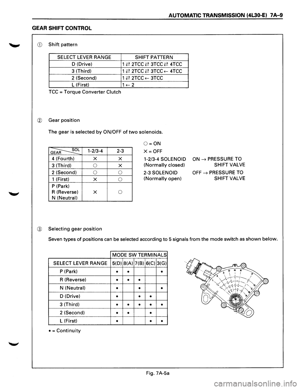
GEAR SHIFT CONTROL
CD Shift pattern
SELECT
LEVER RANGE SHIFT PATTERN
D (Drive)
1
~ 2TCC ~ 3TCC ~ 4TCC
3 (Third)
1 ~ 2TCC ~ 3TCC f-4TCC
2 (Second)
1 ~ 2TCC f-3TCC
L (First) 1f-2
TCC =Torque Converter Clutch
® Gear position
The gear is selected by ON/OFF of two solenoids.
G~ 1-2/3-4
4 (Fourth)
X
3 (Third)
0
2 (Second) 0
1 (First)
X
P (Park)
R (Reverse)
X
N
(Neutral)
@ Selecting
gear position
2-3
X
X
0
0
0
0=0N
X=OFF
1-2/3-4 SOLENOID
(Normally closed)
2-3 SOLENOID
(Normally open)
ON ~ PRESSURE TO
SHIFT
VALVE
OFF~ PRESSURE TO
SHIFT VALVE
Seven types
of positions can be selected according to 5 signals from the mode switch as shown below.
MODE
SW TERMINALS
SELECT LEVER RANGE 5(D)
8(A) 7(8) 6(C) 3(G)
P (Park)
• • •
R (Reverse) • • •
N (Neutral) • • •
D (Drive) • • •
3 (Third) • • • • •
2 (Second) • • •
L (First) • • •
• =Continuity
Fig. 7A-5a
Page 882 of 1928
7A-10 AUTOMATIC TRANSMISSION (4L30-E)
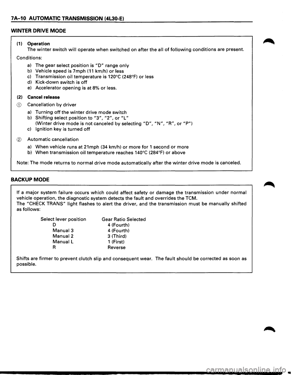
WINTER DRIVE MODE
(1) Operation
The winter switch will operate when switched on after the all of following conditions are present.
Conditions:
a) The gear select position is "D" range only
b) Vehicle speed is 7mph (11 km/h) or less
c) Transmission oil temperature is 120°C (248°F) or less
d) Kick-down switch is off
e) Accelerator opening is at 8% or less.
(2) Cancel release
CD Cancellation by driver
a) Turning off the winter drive mode switch
b) Shifting select position to "3", "2", or "L"
(Winter drive mode is not canceled by selecting "D", "N", "R", or "P")
c) Ignition key is turned off
® Automatic cancellation
a) When vehicle runs at 21mph (34 km/h) or more for 1 second or more
b) When transmission oil temperature reaches 140°C (284°F) or above
Note: The mode returns
to normal drive mode automatically after the winter drive mode is canceled.
BACKUP MODE
If a major system failure occurs which could affect safety or damage the transmission under normal
vehicle operation, the diagnostic system detects the fault and overrides the TCM.
The "CHECK TRANS" light flashes to alert the driver, and the transmission must be manually shifted
as follows:
Select lever
position
D
Manual3
Manual2
Manual L
R
Gear Ratio Selected
4 (Fourth)
4 (Fourth)
3 (Third)
1 (First)
Reverse
Shifts are firmer to prevent clutch slip and consequent wear. The fault should be corrected as soon as
possible.
Page 883 of 1928

AUTOMATIC TRANSMISSION (4L30-E) 7 A-11
FUNCTIONS OF INPUT /OUTPUT COMPONENTS
Components Function
Speed sensor
Senses rotation
of output shaft and feeds the data to Transmission
(fixed
to transmission (T/M)) Control Module (TCM)
Throttle Senses the extent of throttle valve opening and the speed of the throttle
position sensor (TPS) valve lever motion to open the valve and feeds the data to TCM (fed to
(fixed to engine)
Engine Control Module (ECM) also)
I
Brake Switch (SW) Senses whether the driver has pressed the brake pedal or not and feeds
N (fixed
to brake pedal) the
information to TCM
p Kick-down SW (fixed to Senses whether the driver has pushed the accelerator pedal fully or not
u accelerator pedal) and feeds the information to TCM
T Mode
SW (fixed to T/M) Senses the select lever position and feeds the information to TCM
s Power drive SW Senses whether the driver has selected the power mode and feeds the
I (fixed to front console) information to TCM
G T/M
oil temp. sensor
Senses the T/M oil temperature and feeds the data to TCM
N Engine
coolant Senses the engine cooling water temperature and feeds the data to TCM
A temperature
SW (feeds the signal from ECM)
L
Engine speed
signal Feeds the signals monitoring engine speed to TCM from Ignition Control
Module
(fed to ECM also)
Air conditioning Senses whether the air conditioner has been switched on or not and
information feeds the information
to TCM
On-board diagnostic
input By monitoring the Ground (GND), the location of failure is shown on the
T/M
monitor lamp ("CHECK TRANS") by flashing the diagnostic trouble
code
Winter switch
Senses whether the driver has selected the winter mode, and feeds the
(fixed
to front console) information to TCM
Cruise
controller Downshift takes place when Overdrive OFF signal is received from auto
(Overdrive
OFF signal) cruise control unit
Shift
solenoid Selects shift point and gear position suited to the vehicle running con-s 1-2/3-4, 2-3
dition on the basis of TCM output 0 Band apply solenoid
Controls oil flow suited to the vehicle running condition on the basis of L
E TCM output
0 N
Torque
Converter Controls clutch engagement/disengagement suited to the vehicle
u 0 Clutch solenoid running condition on the basis of TCM output
T I Force motor Adjusts the oil pump delivery pressure to line pressure suited to the p D
(Pressure regulator vehicle running condition on the basis of TCM output u valve) T
Power drive mode lamp
Informs the driver whether the vehicle is in power mode or not
s Winter drive mode lamp Informs the driver whether the vehicle is in winter mode or not
I T/M monitor lamp Informs the driver of failure in the system. It also displays the self diagnosis
G
("CHECK TRANS") code.
N Data Link Connector
(DLC) When connected with TECH 1 or tester, can communicate the data for A
L function
check, etc. (fed to ECM also). When TECH 1 is not connected, can
communicate the
signal for torque management with ECM.
Self-diagnosis connector
When short-circuited with the bipolar connector, the T/M monitor lamp
displays
a failure by code.
ATF warning
lamp Lights when ATF oil temperature rises.
ABS signal When the select lever is at "Reverse" or "L" range, sends a signal to the
ABS controller as one of the ABS control conditions.
Page 884 of 1928
7A-12 AUTOMATIC TRANSMISSION (4L30-E)
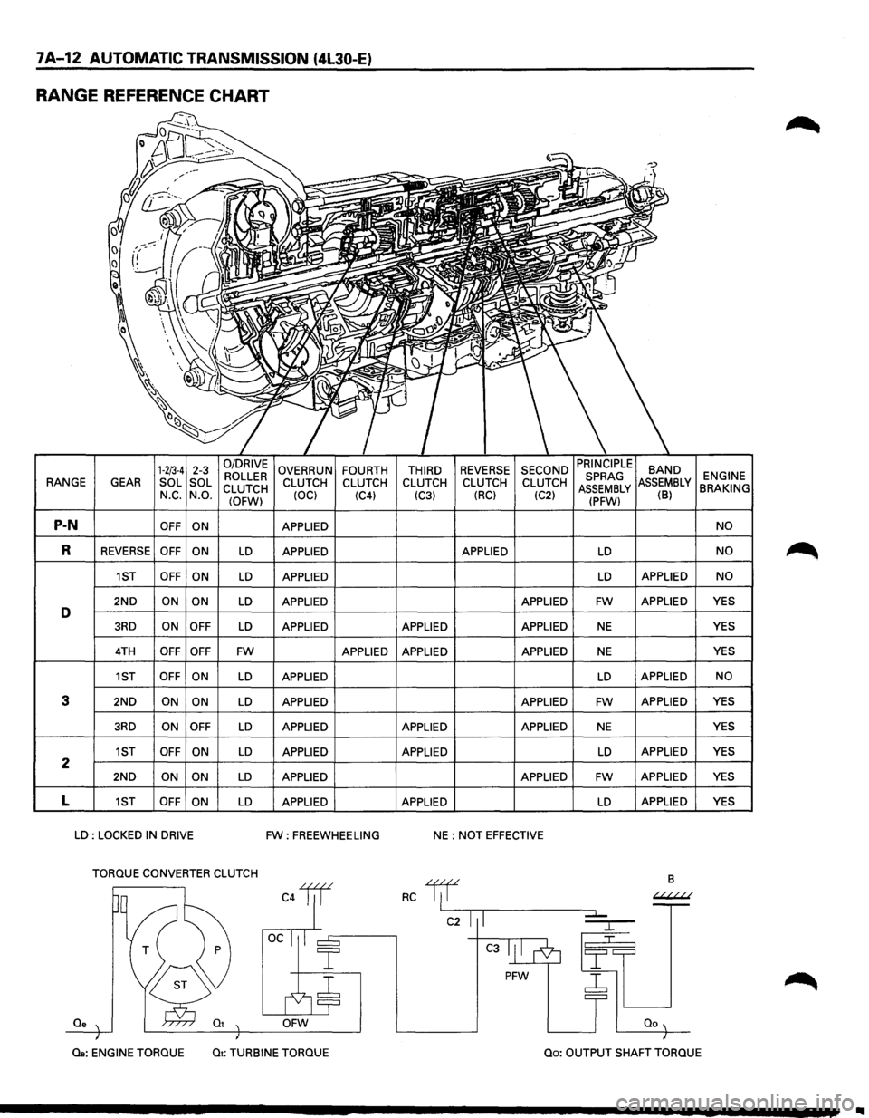
RANGE REFERENCE CHART
1-2/3-4 2-3 0/DRIVE OVERRUN FOURTH THIRD REVERSE SECOND BAND ROLLER ENGINE RANGE
GEAR SOL
SOL
CLUTCH CLUTCH
CLUTCH CLUTCH CLUTCH CLUTCH MBLY BRAKING N_c. N.O.
(OFW) (OCl
(C4)
(C3) (RC)
(C2) (B)
P-N OFF
ON APPLIED NO
R REVERSE OFF
ON LD APPLIED APPLIED LD NO
1ST OFF
ON LD APPLIED LD APPLIED NO
2ND ON ON LD APPLIED APPLIED FW APPLIED YES D 3RD ON
OFF LD APPLIED APPLIED APPLIED NE YES
4TH OFF OFF FW APPLIED APPLIED APPLIED NE YES
1ST OFF ON
LD APPLIED LD APPLIED NO
3 2ND ON ON LD APPLIED APPLIED FW APPLIED
YES
3RD ON OFF LD APPLIED APPLIED APPLIED NE YES
1ST OFF
ON LD APPLIED APPLIED LD APPLIED YES 2 2ND ON
ON LD APPLIED APPLIED FW APPLIED YES
L 1ST OFF
ON LD APPLIED APPLIED LD APPLIED
YES
LD : LOCKED IN DRIVE FW: FREEWHEELING NE : NOT EFFECTIVE
TORQUE CONVERTER CLUTCH
B
C4lil RC 1/f ~
C2 I I
C3
PFW ~
Qe OFW
Qe: ENGINE
TORQUE Qt: TURBINE TORQUE Qo: OUTPUT SHAFT TORQUE
Page 885 of 1928
AUTOMATIC TRANSMISSION (4L30-E) 7A-13
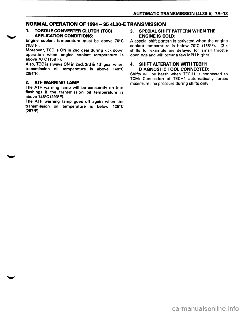
NORMAL OPERATION OF 1994-95 4L30-E TRANSMISSION
1. TORQUE CONVERTER CLUTCH (TCC)
APPLICATION CONDITIONS:
Engine coolant temperature must be above 70°C
(158°F).
Moreover, TCC is ON in 2nd gear during kick down
operation when engine coolant temperature is
above
70°C (158°F).
Also,
TCC is always ON in 2nd, 3rd & 4th gear when
transmission oil temperature is above 140°C
(284°F).
2. ATF WARNING LAMP
The ATF warning lamp will be constantly on (not
flashing) if the transmission oil temperature is
above
145°C (293°F).
The ATF warning lamp goes off again when the
transmission
oil temperature is below 125°C
(257°F).
3. SPECIAL SHIFT PATTERN WHEN THE
ENGINE IS COLD:
A special shift pattern is activated when the engine
coolant temperature is below 70°C (158°F). (3-4
shifts
for example are delayed for small throttle
openings and will occur a few MPH higher)
4. SHIFT ALTERATION WITH TECH1
DIAGNOSTIC TOOL CONNECTED:
Shifts will be harsh when TECH1 is connected to
TCM: Connection of TECH1 automatically forces
maximum line pressure during shifts only.
Page 886 of 1928
7A-14 AUTOMATIC TRANSMISSION (4l30-E)
MEMO
..
Page 887 of 1928
AUTOMATIC TRANSMISSION (4L30-E) 7A-15
DIAGNOSIS
. .,._., INTRODUCTION
The systematic trouble shooting information covered by this Section offers a practical and systematic
approach
to diagnosing 4L30-E transmission, using information that can be obtained from road tests,
electrical diagnosis, oil pressure checks or noise evaluation.
The key to correcting a complaint is to make use of all of the available symptoms and logically letting them
direct you
to the cause.
When
dealing with automatic transmission complaints, it is best to gather as many symptoms as possible
before making the decision to remove the transmission from the vehicle.
Frequently,
the correction of the cause of the complaint does not require removal of the transmission from
the vehicle.