transmission ISUZU TROOPER 1995 Repair Manual
[x] Cancel search | Manufacturer: ISUZU, Model Year: 1995, Model line: TROOPER, Model: ISUZU TROOPER 1995Pages: 1928
Page 657 of 1928
ENGINE ELECTRICAL 601-3
ON-VEHICLE SERVICE
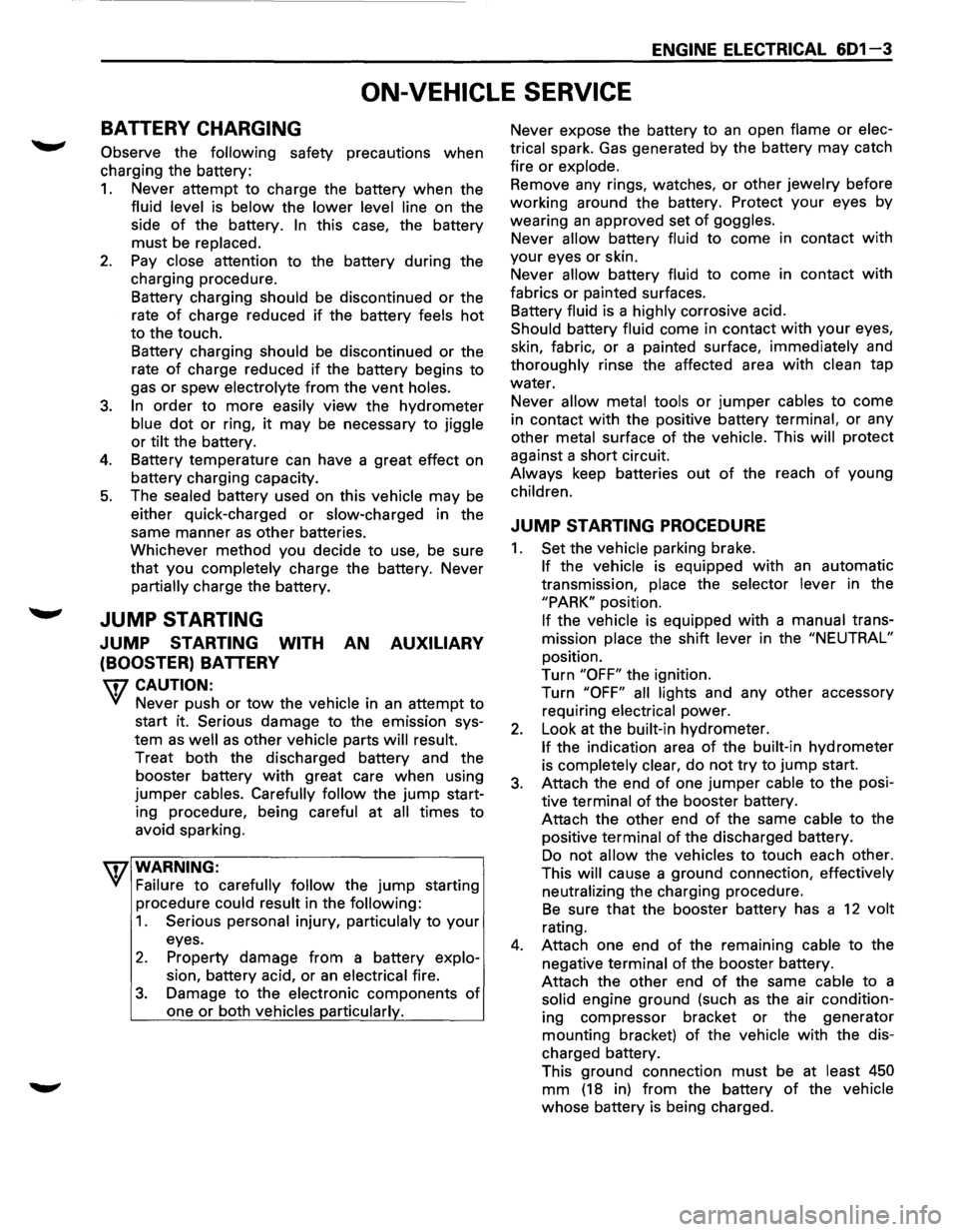
BATTERY CHARGING
Observe the following safety precautions when
charging the battery:
1. Never attempt to charge the battery when the
fluid level is below the lower level line on the
side
of the battery. In this case, the battery
must be replaced.
2. Pay close attention to the battery during the
charging procedure.
Battery charging
should be discontinued or the
rate
of charge reduced if the battery feels hot
to the touch.
Battery charging
should be discontinued or the
rate
of charge reduced if the battery begins to
gas or spew electrolyte from the vent holes.
3. In order to more easily view the hydrometer
blue dot or ring, it may be necessary to jiggle
or tilt the battery.
4. Battery temperature can have a great effect on
battery charging capacity.
5. The sealed battery used on this vehicle may be
either quick-charged or slow-charged in the
same manner
as other batteries.
Whichever method you decide
to use, be sure
that you
completely charge the battery. Never
partially charge the battery.
JUMP STARTING
JUMP STARTING WITH AN AUXILIARY
(BOOSTER)
BATTERY
W CAUTION:
Never push or tow the vehicle in an attempt to
start it.
Serious damage to the emission sys
tem as
well as other vehicle parts will result.
Treat both the discharged battery and the
booster battery
with great care when using
jumper cables. Carefully follow the jump start
ing procedure, being
careful at all times to
avoid sparking.
wwARNING:
Failure to carefully follow the jump starting
procedure
could result in the following:
1. Serious personal injury, particulaly to your
eyes.
2. Property damage from a battery explo
sion, battery acid, or an electrical fire.
3. Damage to the electronic components of
one or both vehicles particularly.
Never expose the battery to an open flame or elec
trical
spark. Gas generated by the battery may catch
fire
or explode.
Remove any rings, watches, or other jewelry before
working around the battery. Protect
your eyes by
wearing
an approved set of goggles.
Never allow battery fluid to come in contact with
your eyes or skin.
Never
allow battery fluid to come in contact with
fabrics or painted surfaces.
Battery
fluid is a highly corrosive acid.
Should battery fluid come in contact with your eyes,
skin, fabric, or a painted surface,
immediately and
thoroughly rinse the affected area with clean tap
water. Never
allow metal tools or jumper cables to come
in contact with the positive battery
terminal, or any
other
metal surface of the vehicle. This will protect
against a short circuit.
Always keep batteries out of the reach of young
children.
JUMP STARTING PROCEDURE
1. Set the vehicle parking brake.
If the vehicle is equipped with an automatic
transmission,
place the selector lever in the
"PARK" position.
If the vehicle is equipped with a manual trans
mission
place the shift lever in the "NEUTRAL"
position.
Turn
"OFF" the ignition.
Turn
"OFF" all lights and any other accessory
requiring
electrical power.
2. Look at the built-in hydrometer.
If the indication area of the built-in hydrometer
is
completely clear, do not try to jump start.
3. Attach the end of one jumper cable to the posi
tive
terminal of the booster battery.
Attach the other end
of the same cable to the
positive
terminal of the discharged battery.
Do not allow the vehicles to touch each other.
This
will cause a ground connection, effectively
neutralizing
the charging procedure.
Be sure that the booster battery has a 12 volt
rating.
4. Attach one end of the remaining cable to the
negative
terminal of the booster battery.
Attach the other end
of the same cable to a
solid engine ground (such as the air condition
ing compressor bracket or the generator
mounting bracket)
of the vehicle with the dis
charged battery.
This ground connection must be at
least 450
mm (18 in) from the battery of the vehicle
whose battery is being charged.
Page 704 of 1928
6E2-8 DRIVEABILITY AND EMISSIONS
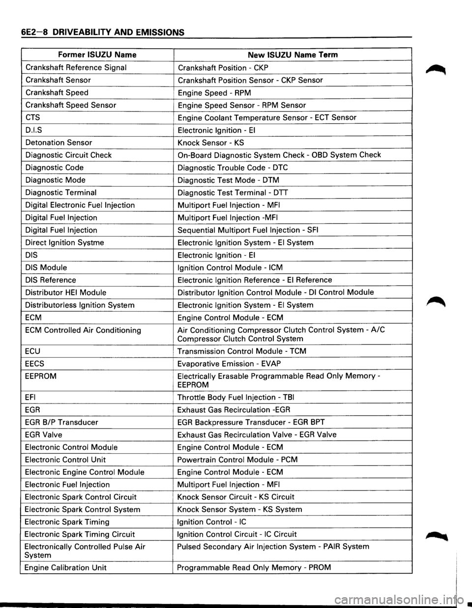
Former ISUZU Name New ISUZU Name Term
Crankshaft Reference Signal Crankshaft Position -CKP
Crankshaft Sensor
Crankshaft Position Sensor -CKP Sensor
Crankshaft Speed
Engine Speed -
RPM
Crankshaft Speed Sensor
Engine Speed Sensor -RPM Sensor
CTS Engine Coolant Temperature Sensor -ECT Sensor
D.I.S Electronic Ignition -El
Detonation Sensor
Knock Sensor-KS
Diagnostic Circuit Check On-Board Diagnostic System Check -OBD System Check
Diagnostic Code Diagnostic Trouble Code -DTC
Diagnostic Mode
Diagnostic Test Mode-DTM
Diagnostic Terminal
Diagnostic Test Terminal -DTT
Digital Electronic
Fuel Injection Multipart Fuel Injection -MFI
Digital Fuel Injection Multipart Fuel Injection -MFI
Digital Fuel Injection Sequential Multipart Fuel Injection -SFI
Direct Ignition Systme Electronic Ignition System -El System
DIS Electronic Ignition -El
DIS Module
Ignition Control Module -ICM
DIS Reference Electronic Ignition Reference -El Reference
Distributor
HEI Module Distributor Ignition Control Module -Dl Control Module
Distributorless Ignition System Electronic Ignition System -
El System
ECM Engine Control Module -ECM
ECM Controlled Air Conditioning Air Conditioning Compressor Clutch Control System -A/C
Compressor Clutch Control System
ECU Transmission Control Module -TCM
EECS Evaporative Emission-EVAP
EEPROM Electrically Erasable Programmable Read Only Memory-
EEPROM
EFI Throttle Body Fuel Injection -TBI
EGR Exhaust Gas Recirculation -EGR
EGR B/P Transducer EGR Backpressure Transducer -EGR BPT
EGR Valve Exhaust Gas Recirculation Valve -EGR Valve
Electronic Control Module Engine Control Module -ECM
Electronic Control Unit Powertrain Control Module -PCM
Electronic Engine Control Module Engine Control Module -ECM
Electronic Fuel Injection Multipart Fuel Injection -MFI
Electronic Spark Control Circuit Knock Sensor Circuit -KS Circuit
Electronic Spark Control System Knock Sensor System -KS System
Electronic Spark Timing Ignition
Control -IC
Electronic Spark Timing Circuit Ignition Control Circuit -IC Circuit
Electronically Controlled Pulse
Air Pulsed Secondary Air Injection System -PAIR System
System
Engine
Calibration Unit Programmable Read Only Memory -PROM
•
Page 707 of 1928
DRIVEABILITY AND EMISSIONS 6E2-11
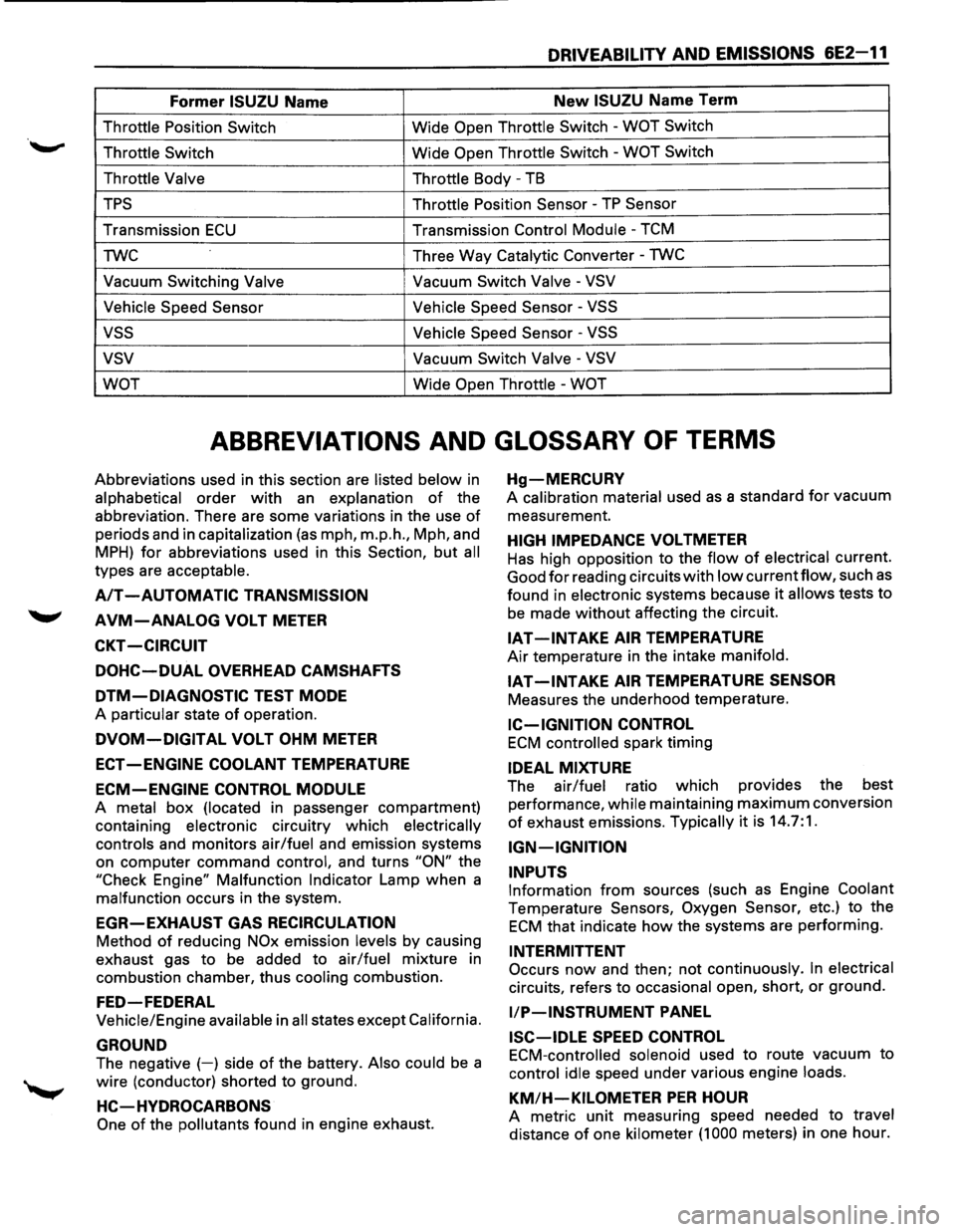
Former ISUZU Name New ISUZU Name Term
Throttle Position Switch Wide Open Throttle Switch -WOT Switch
Throttle Switch
Wide Open Throttle Switch -WOT Switch
Throttle Valve Throttle
Body -TB
TPS Throttle Position Sensor -TP Sensor
Transmission ECU Transmission Control Module -TCM
TWC Three
Way
Catalytic Converter -TWC
Vacuum Switching Valve Vacuum Switch Valve -VSV
Vehicle Speed Sensor Vehicle
Speed Sensor
-VSS
vss Vehicle Speed Sensor -VSS
vsv Vacuum Switch Valve -VSV
WOT
Wide Open Throttle -WOT
ABBREVIATIONS AND GLOSSARY OF TERMS
Abbreviations used in this section are listed below in
alphabetical order with an explanation of the
abbreviation. There are some variations in the use
of
periods and in capitalization (as mph, m.p.h., Mph, and
MPH) for abbreviations used in this Section, but all
types are acceptable.
A/T -AUTOMATIC TRANSMISSION
AVM-ANALOG VOLT METER
CKT -CIRCUIT
DOHC-DUAL OVERHEAD CAMSHAFTS
DTM-DIAGNOSTIC TEST MODE
A particular state of operation.
DVOM-DIGITAL VOLT OHM METER
ECT -ENGINE COOLANT TEMPERATURE
ECM-ENGINE CONTROL MODULE
A metal box (located in passenger compartment)
containing
electronic circuitry which electrically
controls
and monitors air/fuel and emission systems
on
computer command control, and turns "ON" the
"Check Engine"
Malfunction Indicator Lamp when a
malfunction occurs in the system.
EGR-EXHAUST GAS RECIRCULATION
Method of reducing NOx emission levels by causing
exhaust gas
to be added to air/fuel mixture in
combustion chamber, thus
cooling combustion.
FED-FEDERAL
Vehicle/Engine available in all states except California.
GROUND
The negative (-) side of the battery. Also could be a
wire (conductor) shorted to ground.
HC-HVDROCARBONS
One of the pollutants found in engine exhaust.
Hg-MERCURV
A calibration material used as a standard for vacuum
measurement.
HIGH IMPEDANCE VOLTMETER
Has high opposition to the flow of electrical current.
Good
for reading circuits with low currentflow, such as
found in electronic systems because it allows tests to
be made without affecting the circuit.
IAT -INTAKE AIR TEMPERATURE
Air temperature in the intake manifold.
IAT-INTAKE AIR TEMPERATURE SENSOR
Measures the underhood temperature.
IC-IGNITION CONTROL
ECM controlled spark timing
IDEAL MIXTURE
The air/fuel ratio which provides the best
performance,
while maintaining maximum conversion
of exhaust emissions. Typically it is 14.7:1.
IGN-IGNITION
INPUTS
Information from sources (such as Engine Coolant
Temperature Sensors, Oxygen Sensor, etc.) to the
ECM that indicate how the systems are performing.
INTERMITTENT
Occurs now and then; not continuously. In electrical
circuits, refers to occasional open, short, or ground.
liP-INSTRUMENT PANEL
ISC-IDLE SPEED CONTROL
ECM-controlled solenoid used to route vacuum to
control idle speed under various engine loads.
KM/H-KILOMETER PER HOUR
A metric unit measuring speed needed to travel
distance of one kilometer (1 000 meters) in one hour.
Page 708 of 1928
6E2-12 DRIVEABILITY AND EMISSIONS
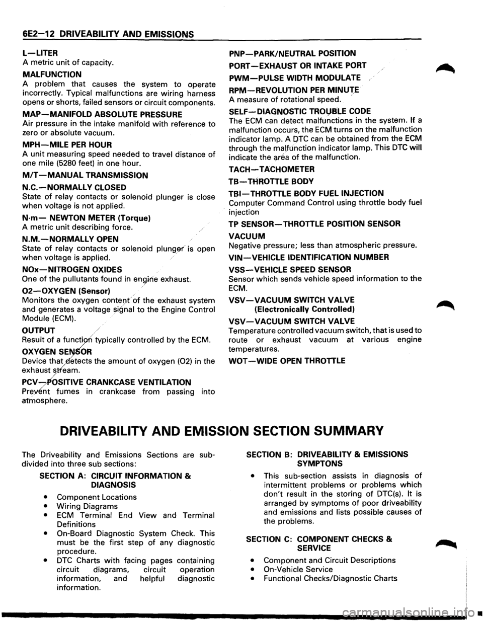
L-LITER
A metric unit of capacity.
MALFUNCTION
A problem that causes the system to operate
incorrectly. Typical malfunctions are wiring harness
opens
or shorts, failed sensors or circuit components.
MAP-MANIFOLD ABSOLUTE PRESSURE
Air pressure in the intake manifold with reference to
zero or absolute vacuum.
MPH-MILE PER HOUR
A unit measuring speed needed to travel distance of
one mile (5280 feet) in one hour.
MIT -MANUAL TRANSMISSION
N.C.-NORMALLY CLOSED
State of relay contacts or solenoid plunger is close
when voltage is not applied.
N·m-NEWTON METER (Torque)
A metric unit describing force.
N.M.-NORMALLY OPEN
State of relay contacts or solenoid plung&r' is open
when voltage is applied.
NOx-NITROGEN OXIDES
One of the pullutants found in engirie exhaust.
02-0XYGEN (Sensor)
Monitors the oxygen contel)f of the exhaust system
and generates a
voltage signal to the Engine Control
Module (ECM).
OUTPUT
Result of a functi typically controlled by the ECM.
OXYGEN SE OR
Device that etects the amount of oxygen (02) in the
exhaust
stfeam. /
PCV-~OSITIVE CRANKCASE VENTILATION
Prey£nt fumes in crankcase from passing into
atmosphere.
PNP-PARK/NEUTRAL POSITION
PORT-EXHAUST OR INTAKE PORT
PWM-PULSE WIDTH MODULATE
RPM-REVOLUTION PER MINUTE
A measure of rotational speed.
SELF-DIAGNOSTIC TROl)SLE CODE
The ECM can detect malfunctions in the system. If a
malfunction occurs, the ECM turns on the malfunction
indicator lamp. A OTC can be obtained from the ECM
through the malfunction indicator lamp. This DTC will
indicate the area of the malfunction.
TACH-TACHOMETER
TB-THROTTLE BODY
TBI-THROTTLE BODY FUEL INJECTION
Computer Command Control using throttle body fuel
injection
TP SENSOR-THROTTLE POSITION SENSOR
VACUUM
Negative pressure; less than atmospheric pressure.
VIN-VEHICLE IDENTIFICATION NUMBER
VSS-VEHICLE SPEED SENSOR
Sensor which sends vehicle speed information to the
ECM.
VSV-VACUUM SWITCH VALVE
(Electronically Controlled)
VSV-VACUUM SWITCH VALVE
Temperature controlled vacuum switch, that is used to
route or exhaust vacuum at various engine
temperatures.
WOT -WIDE OPEN THROTTLE
DRIVEABILITV AND EMISSION SECTION SUMMARY
The Driveability and Emissions Sections are sub
divided into three sub sections:
SECTION A: CIRCUIT INFORMATION &
DIAGNOSIS
• Component Locations
• Wiring Diagrams
• ECM Terminal End View and Terminal
Definitions
• On-Board Diagnostic System Check. This
must be the first step of any diagnostic
procedure.
• DTC Charts with facing pages containing
circuit diagrams, circuit operation
information, and
helpful diagnostic
information.
SECTION B: DRIVEABILITY & EMISSIONS
SYMPTONS
• This sub-section assists in diagnosis of
intermittent problems or problems which
don't result in the storing of DTC(s). It is
arranged
by symptoms of poor driveability
and emissions and lists possible causes of
the problems.
SECTION C: COMPONENT CHECKS &
SERVICE
• Component and Circuit Descriptions
• On-Vehicle Service
• Functional
Checks/Diagnostic Charts
•
Page 713 of 1928
DRIVEABILITY AND EMISSIONS 6E2-17
I OPERATING CONDITIONS READ I
I SYSTEMS CONTROLLED I
• Air Conditioning "On" or "Off" • Evaporative Emission Canister
• Engine Coolant Temperature Purge
• Crankshaft Position • Exhaust Gas Recirculation
• Exhaust Heated Oxygen Sensor • Ignition Control
• Electronic Ignition Reference • Fuel Control
• Crankshaft Position
ENGINE • Idle Air Control
• Engine Speed (RPM} CONTROL • Electric Fuel Pump
• Manifold Absolute Pressure (MAP)
MODULE • Air Conditioning
• Battery Positive Voltage (ECM) • Diagnostics
• Throttle Position Sensor • Malfunction Indicator Lamp
• Vehicle Speed Sensor • Diagnostic Test Terminal
• Fuel Pump Voltage • Data Output
• Power Steering Pressure • Transmission Control Module
• Intake Air Temperature • Knock Sensor (DOHC)
• Differential Pressure • Induction Air Control Plate System
• Knock Sensor (DOHC)
(DOHC)
• Exhaust Gas Recirculation Vacuum
• Air Conditioning High Side Pressure
Fig. 6E2-3
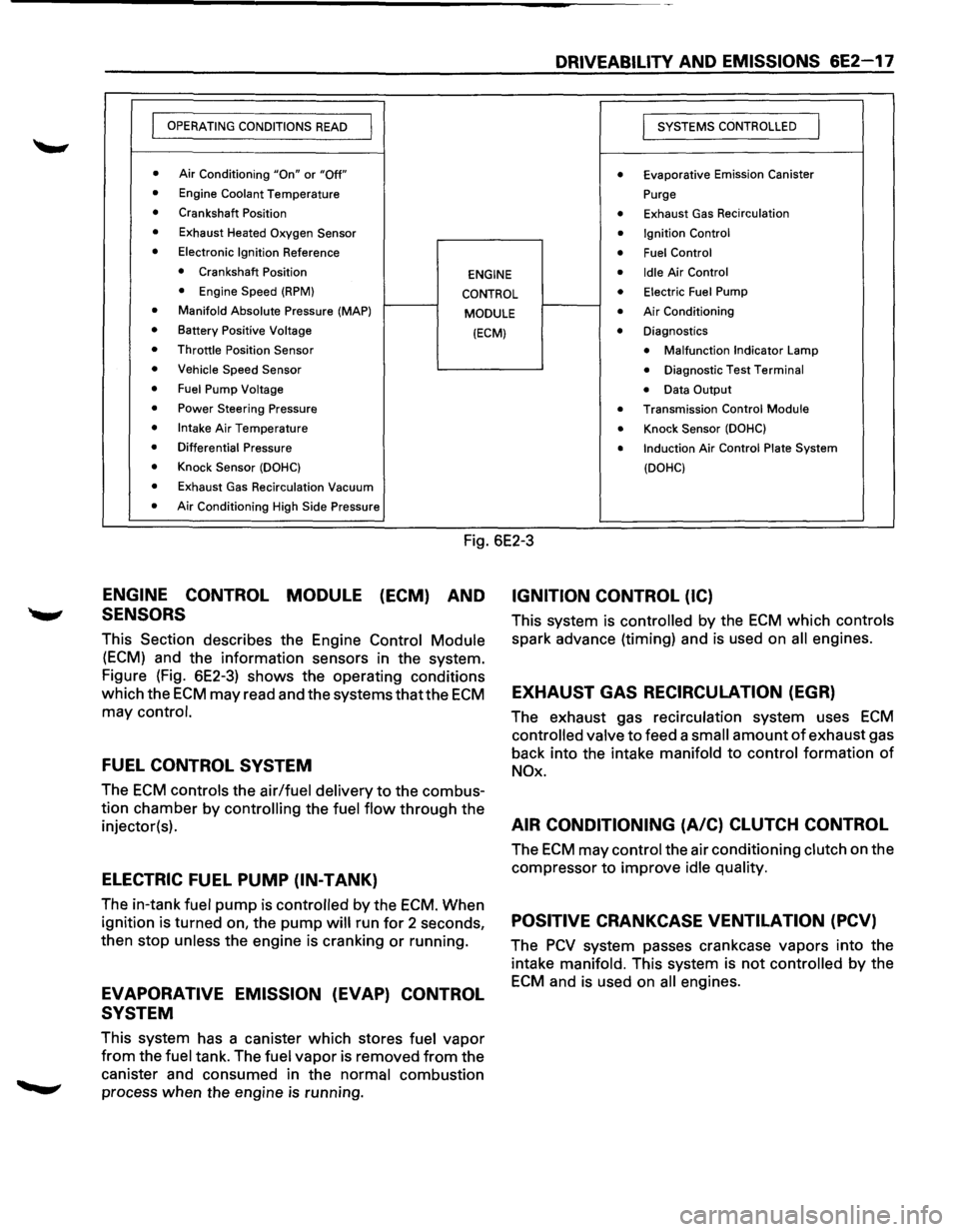
ENGINE CONTROL MODULE (ECM) AND
SENSORS
This Section describes the Engine Control Module
(ECM) and the information sensors in the system.
Figure (Fig. 6E2-3) shows the operating conditions
which the
ECM may read and the systems thatthe ECM
may control.
FUEL CONTROL SYSTEM
The ECM controls the air/fuel delivery to the combus
tion chamber by
controlling the fuel flow through the
injector(s).
ELECTRIC FUEL PUMP (IN-TANK)
The in-tank fuel pump is controlled by the ECM. When
ignition is turned on, the
pump will run for 2 seconds,
then stop
unless the engine is cranking or running.
EVAPORATIVE EMISSION (EVAP) CONTROL
SYSTEM
This system has a canister which stores fuel vapor
from the fuel tank. The fuel vapor is removed from the
canister and consumed in the
normal combustion
process when the engine
is running.
IGNITION CONTROL (IC)
This system is controlled by the ECM which controls
spark advance (timing) and is used on all engines.
EXHAUST GAS RECIRCULATION (EGR)
The exhaust gas recirculation system uses ECM
controlled valve to feed a small amount of exhaust gas
back into the intake
manifold to control formation of
NOx.
AIR CONDITIONING (A/C) CLUTCH CONTROL
The ECM may control the air conditioning clutch on the
compressor
to improve idle quality.
POSITIVE CRANKCASE VENTILATION (PCV)
The PCV system passes crankcase vapors into the
intake
manifold. This system is not controlled by the
ECM and is used on all engines.
Page 724 of 1928
6E2-28 DRIVEABILITV AND EMISSIONS
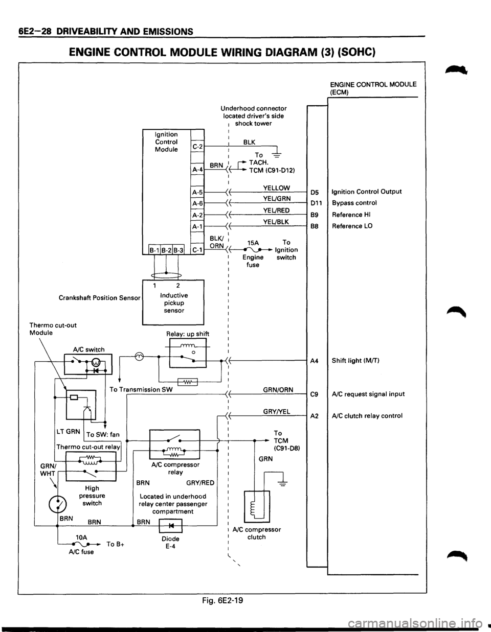
ENGINE CONTROL MODULE WIRING DIAGRAM (3) (SOHC)
Ignition Control
Module Underhood
connector
located driver's side
1 shock tower I I 1:-2~--~~--~B~L~K~--~
- : To -4-
-BRN 1. r--TACH.
A-4 ~ TCM IC91-D12) -I
I
YELLOW
·~ YEL!GRN \ VEL/RED YEL!BLK
I--B-1IB-2IB-3l C-1
l
1 2
Crankshaft Position Sensor Inductive pickup
sensor I
I
I
I
Thermo cut-out I
I
I
I
I
n I
Mo\\I•Silj ~~
To Transmission SW ~ r-------------------~ -
'---<
LT GRN To SW: fan
Thermo cut-out relay'
GRN/
WHT
....--+-----~
BRN
High
pressure switch
BRN
NC compressor relay
BRN GRY/RED
Located in underhood relay center passenger
compartment
BRN r::-1
I
I
r
I
I
I
I
I
I
I
I
I
I
I
I
I
I
GRN/ORN
GRY!YEL To
TCM IC91-D8)
GRN
n
l
I I 1 NC compressor 10A ~ToB+ NCfuse
Diode E-4
I clutch I
I
' ' '
Fig. 6E2-19
A4
C9
A2
~
ENGINE CONTROL MODULE (ECM)
Reference HI
Reference LO
Shift light (MfT)
NC request signal input
NC clutch relay control
..
Page 754 of 1928
6E2-58 DRIVEABILITY AND EMISSIONS
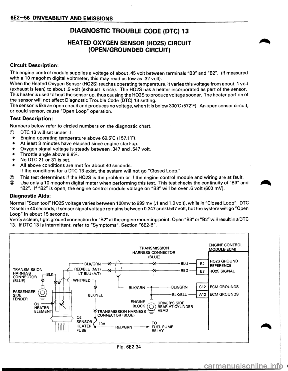
Circuit Description:
DIAGNOSTIC TROUBLE CODE (DTC) 13
HEATED OXYGEN SENSOR (H02S) CIRCUIT
(OPEN/GROUNDED CIRCUIT)
The engine control module supplies a voltage of about .45 volt between terminals "83" and "82". (If measured
with a
10 megohm digital voltmeter, this may read as low as .32 volt).
When the Heated Oxygen Sensor (H02S) reaches operating temperature, it varies this voltage from about .1 volt
(exhaust is lean) to about .9 volt (exhaust is rich). The H02S has a heater incorporated as part of the sensor.
This heater is used to
heatthe sensor up, thus causing the H02S to produce voltage sooner. The heater portion of
the sensor
will not affect Diagnostic Trouble Code (DTC) 13 setting.
The sensor
is like an open circuit and produces no voltage, when it is below 3oo·c (572.F). An open sensor circuit,
or could sensor, cause "Open Loop" operation.
Test Description:
Numbers below refer to circled numbers on the diagnostic chart.
• At least 3 minutes have elapsed since engine start-up.
• Oxygen signal voltage is steady between .347 and .547 volt.
• Throttle angle
above 9.8%.
• No DTC 21 or 31 is set.
• All above conditions are met for about 40 seconds.
If the conditions for a DTC 13 exist, the system will not go "Closed Loop."
® This test determines if the H02S is the problem or if the engine control module and wiring are at fault.
@ Use only a 10 megohm digital meter when performing this test. This test checks the continuity of "83" and
"82". If "82" is open, the engine control module voltage on "83" will be over .6 volt (600 mV).
Diagnostic Aids:
Normal "Scan tool" H02S voltage varies between 1 OOmv to 999 mv (.1 and 1.0 volt), while in "Closed Loop". DTC
13 sets in 40 seconds, if sensor signal voltage remains between 0.347 and 0.547 volt, but the system will go "Open
Loop"
in about 15 seconds.
Verify a
clean, tight ground connection for "82" at the engine mounting point. Open "83" or "82" will result in a DTC
13. If DTC 13 is intermittent, refer to "Symptoms", Section "6E2-8".
TRANSMISSION
HARNESS BLK CONNECTOR r 1
TRANSMISSION
HARNESS CONNECTOR
(BLUE) I /'< r--BLK/GRN ~~,---.,------«----BLU
RED/BLU (MIT) --« ! « RED
(BLUE) ~
PASSENGER Q SIDE
L T BLU (A/T) L
WHT/RED 1
P=H=~ r BLK/GRN ---.---BLK!GRN
BLK!YEL BLK!BLU FENDER
02 -----·'$ HEATER ELEMENT
02
l
ENGINE
BLOCK
TRANSMISSION HARNESS
-CONNECTOR (BLUE)
DRIVER'S SIDE REAR AT CYLINDER HEAD
SENSOR 10A TO
HEATER ---RED/GRN --• FUEL PUMP FUSE RELAY
Fig. 6E2-34
ENGINE CONTROL
MODULE(ECM)
H02S GROUND REFERENCE
H02S SIGNAL
ECM GROUNDS
ECM GROUNDS
•
Page 760 of 1928
/
6E2-64 DRIVEABILITY AND EMISSIONS
Circuit Description:
DIAGNOSTIC TROUBLE CODE (DTC) 21A
THROTTLE POSITION (TP) SENSOR CIRCUIT
(SIGNAL
VOLTAGE HIGH)
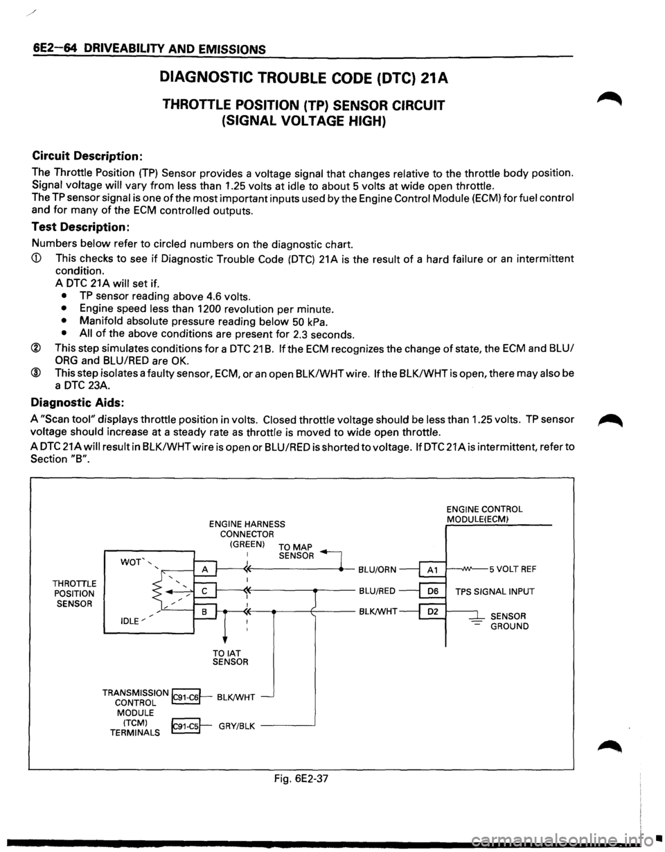
The Throttle Position (TP) Sensor provides a voltage signal that changes relative to the throttle body position.
Signal voltage
will vary from less than 1.25 volts at idle to about 5 volts at wide open throttle.
The
TP sensor signal is one of the most important inputs used by the Engine Control Module (ECM) for fuel control
and
for many of the ECM controlled outputs.
Test Description:
Numbers below refer to circled numbers on the diagnostic chart.
A
DTC 21 A will set if.
• TP sensor reading above 4.6 volts.
• Engine speed less than 1200 revolution per minute.
• Manifold absolute pressure reading below 50 kPa.
• All of the above conditions are present for 2.3 seconds.
® This step simulates conditions for a DTC 21 B. If the ECM recognizes the change of state, the ECM and BLU/
ORG and BLU/RED are OK.
® This step isolates a faulty sensor, ECM, or an open BLK/WHTwire. If the BLK/WHTis open, there may also be
a
DTC 23A.
Diagnostic Aids:
A "Scan tool" displays throttle position in volts. Closed throttle voltage should be less than 1.25 volts. TP sensor ~
voltage should increase at a steady rate as throttle is moved to wide open throttle.
A
DTC 21Awill result in BLK/WHTwire is open or BLU/RED is shorted to voltage. If DTC 21A is intermittent, refer to
Section "8".
THROTILE
POSITION
SENSOR
WOT',
IDLE"' ENGINE
HARNESS
CONNECTOR
(GREEN) TO MAP
TOIAT SENSOR SENSOR
TRANSMISSION~ BLK/WHT CONTROL ~-
MODULE
(TCM)
~ GRY/BLK -----.J TERMINALS ~
Fig. 6E2-37
ENGINE CONTROL
MODULE(ECM)
SENSOR
-GROUND
•
Page 762 of 1928
6E2-66 DRIVEABILITV AND EMISSIONS
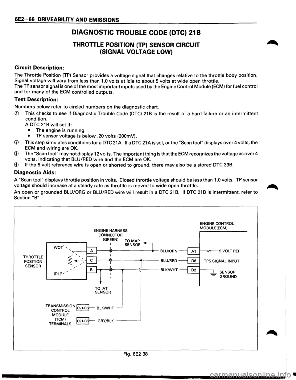
DIAGNOSTIC TROUBLE CODE (DTC) 21 8
THROTILE POSITION (TP) SENSOR CIRCUIT
(SIGNAL VOLTAGE LOW)
Circuit Description:
The Throttle Position (TP) Sensor provides a voltage signal that changes relative to the throttle body position.
Signal voltage will vary from less than 1.0 volts at idle to about 5 volts at wide open throttle.
The
TP sensor signal is one of the most important inputs used by the Engine Control Module (ECM) for fuel control
and
for many of the ECM controlled outputs.
Test Description:
Numbers below refer to circled numbers on the diagnostic chart.
CD This checks to see if Diagnostic Trouble Code (DTC) 21 B is the result of a hard failure or an intermittent
condition.
A
DTC 21 B will set if:
• The engine is running
• TP sensor voltage is below .20 volts (200mV).
® This step simulates conditions for a DTC 21 A. If a DTC 21 A is set, or the "Scan tool" displays over 4 volts, the
ECM and wiring are OK.
® The "Scan tool" may not display 12 volts. The important thing is thatthe ECM recognizes the voltage as over 4
volts, indicating that BLU/RED wire and the ECM are OK.
@ If the 5 volt reference wire is open or shorted to ground, there may also be a stored DTC 338.
Diagnostic Aids:
A "Scan tool" displays throttle position in volts. Closed throttle voltage should be less than 1.0 volts. TP sensor
voltage should increase at
a steady rate as throttle is moved to wide open throttle. ~
An open or grounded BLU/ORG or BLUIRED wire will result in a DTC 21 B. If DTC 21 B is intermittent, refer to
Section "8".
THROTTLE POSITION
SENSOR ENGINE
HARNESS
CONNECTOR
WOT',
IDLE"'
(GREEN) TO MAP
TOIAT SENSOR SENSOR
TRANSMISSION~ BLK/WHT CONTROL ~ MODULE
(TCM) IC91-C6'-GRY/BLK -----..J TERMINALS ~ -
Fig. 6E2-38
ENGINE
CONTROL
MODULE(ECMl
1---..JW--5 VOLT REF
TPS SIGNAL INPUT
SENSOR
- GROUND
•
Page 771 of 1928
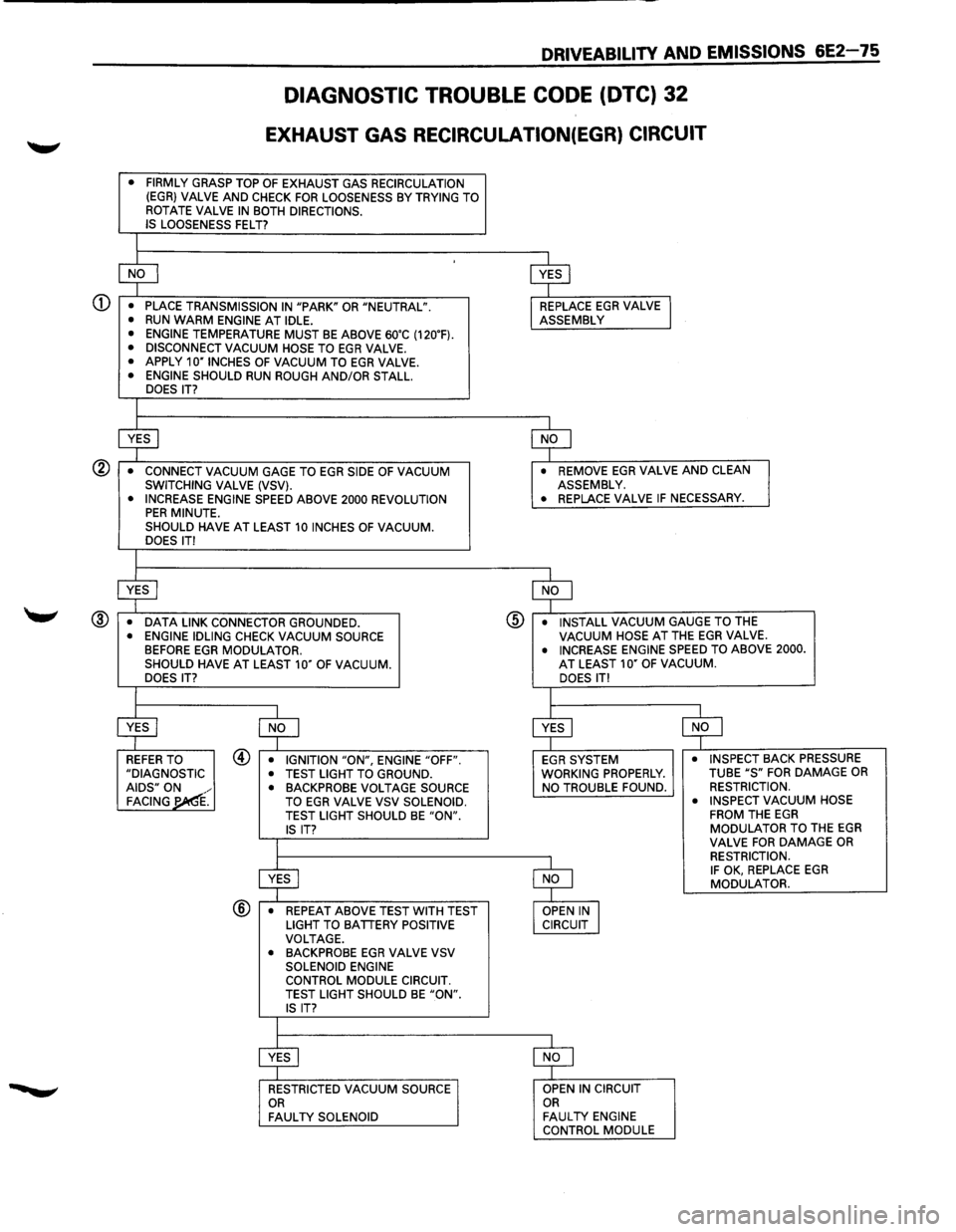
DIAGNOSTIC TROUBLE CODE (DTC) 32
EXHAUST GAS RECIRCULATION(EGR) CIRCUIT
• FIRMLY GRASP TOP OF EXHAUST GAS RECIRCULATION (EGR} VALVE AND CHECK FOR LOOSENESS BY TRYING TO
ROTATE VALVE IN BOTH DIRECTIONS.
IS LOOSENESS FELT?
l
$
-[$J
• PLACE TRANSMISSION IN "PARK" OR "NEUTRAL". REPLACE EGR VALVE I • RUN WARM ENGINE AT IDLE. ASSEMBLY
• ENGINE TEMPERATURE MUST BE ABOVE 60'C (120'F). • DISCONNECT VACUUM HOSE TO EGR VALVE. • APPLY 10"1NCHES OF VACUUM TO EGR VALVE. • ENGINE SHOULD RUN ROUGH AND/OR STALL.
DOES IT?
I
$ $
•
CONNECT VACUUM GAGE TO EGR SIDE OF VACUUM • REMOVE EGR VALVE AND CLEAN SWITCHING VALVE (VSV). ASSEMBLY.
• INCREASE ENGINE SPEED ABOVE 2000 REVOLUTION • REPLACE
VALVE IF NECESSARY. PER MINUTE.
SHOULD HAVE AT LEAST 10 INCHES OF VACUUM. DOES IT!
I
$ $
• DATA LINK CONNECTOR GROUNDED . @ • INSTALL VACUUM GAUGE TO THE
• ENGINE IDLING CHECK VACUUM SOURCE VACUUM HOSE AT THE EGR VALVE. BEFORE EGR MODULATOR. • INCREASE ENGINE SPEED TO ABOVE 2000 . SHOULD HAVE AT LEAST 10" OF VACUUM. AT LEAST 10" OF VACUUM. DOES IT? DOES IT!
I
I
$ $ $ ~
REFER TO @ • IGNITION "ON", ENGINE "OFF". EGR SYSTEM • INSPECT BACK PRESSURE
"DIAGNOSTIC • TEST LIGHT TO GROUND. WORKING PROPERLY. TUBE "S" FOR DAMAGE OR AIDS" ON
.
• BACKPROBE VOLTAGE SOURCE NO
TROUBLE FOUND. RESTRICTION. FACING'¢{ TO EGR VALVE VSV
SOLENOID. •
INSPECT VACUUM HOSE
TEST LIGHT SHOULD BE "ON". FROM THE EGR
IS IT? MODULATOR TO THE EGR
I VALVE FOR DAMAGE OR
$ $
RESTRICTION. IF OK, REPLACE EGR MODULATOR.
@ • REPEAT ABOVE TEST WITH TEST
OPEN IN I LIGHT TO BATTERY POSITIVE CIRCUIT VOLTAGE.
• BACKPROBE EGR VALVE VSV
SOLENOID ENGINE
CONTROL MODULE CIRCUIT.
TEST LIGHT SHOULD
BE "ON". IS IT?
I
$ $
RESTRICTED VACUUM SOURCE OPEN
IN CIRCUIT OR OR FAULTY SOLENOID FAULTY ENGINE
CONTROL MODULE