transmission ISUZU TROOPER 1995 Service Manual
[x] Cancel search | Manufacturer: ISUZU, Model Year: 1995, Model line: TROOPER, Model: ISUZU TROOPER 1995Pages: 1928
Page 481 of 1928
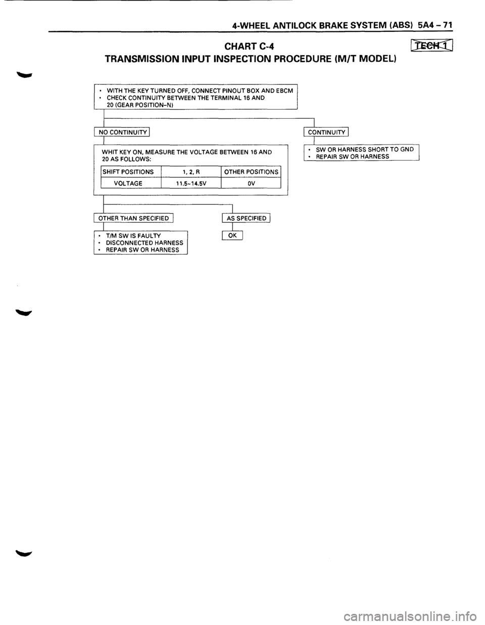
4-WHEEL ANTILOCK BRAKE SYSTEM (ABS) 5A4 -71
CHART C-4 [JEefl:(l
TRANSMISSION INPUT INSPECTION PROCEDURE (M/T MODEL)
• WITH THE KEY TURNED OFF, CONNECT PINOUT BOX AND EBCM • CHECK CONTINUITY BETWEEN THE TERMINAL 16 AND 20 (GEAR POSITION-N)
I
I I
NO
CONTINUITY I I CONTINUITY I
I I
WHIT KEY ON, MEASURE
THE VOLTAGE BETWEEN 16 AND I . sw OR HARNESS SHORT TO GND I
20 AS FOLLOWS: •
REPAIR SW OR HARNESS
I SHIFT POSITIONS I 1, 2, R I OTHER POSITIONS I
I
VOLTAGE I 11.5-14.5V I ov I
I
I I
OTHER THAN SPECIFIED I
I AS SPECIFIED I
I @ . T/M SW IS FAULTY • DISCONNECTED HARNESS • REPAIR SW OR HARNESS
Page 482 of 1928
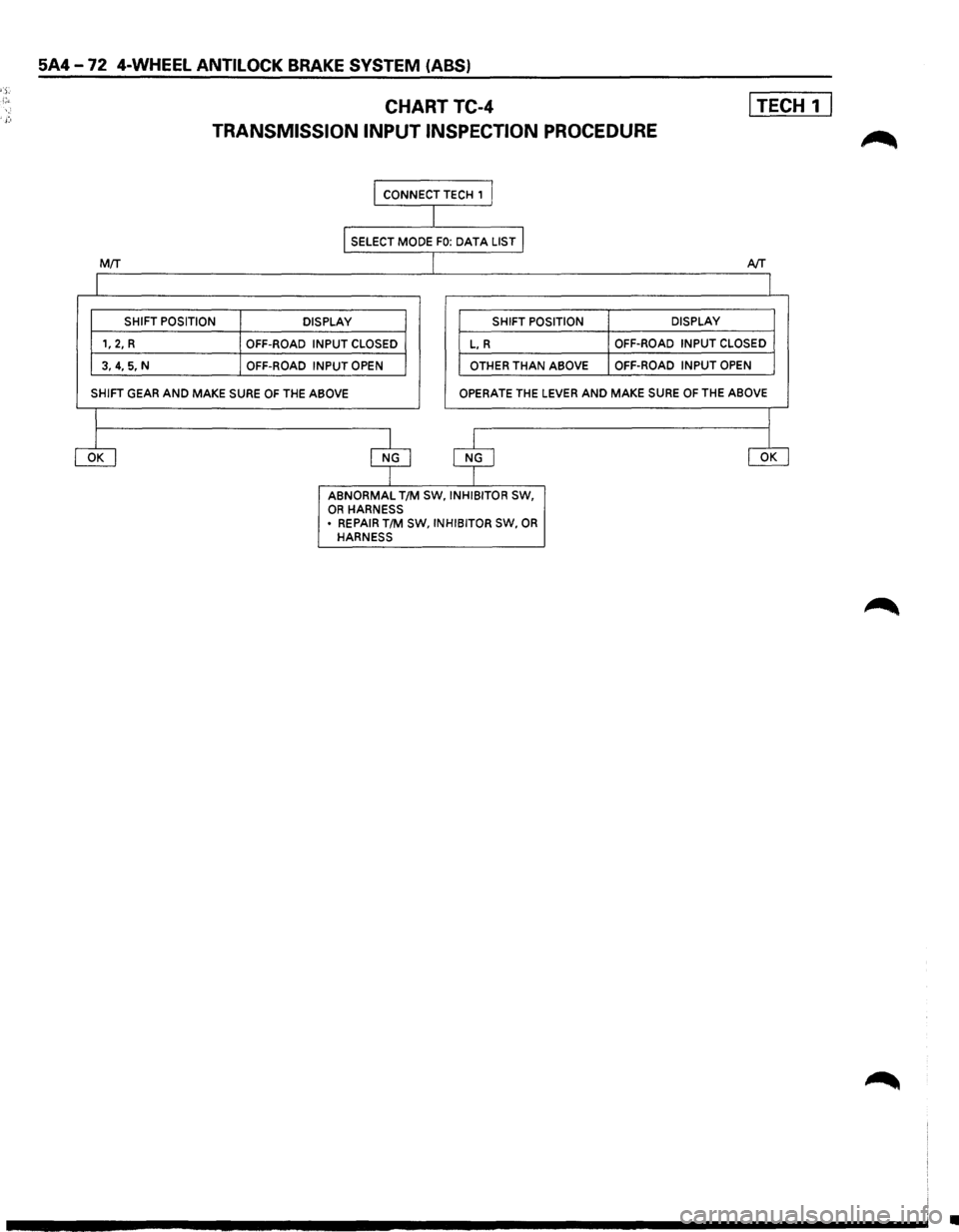
5A4-72 4-WHEEL ANTILOCK BRAKE SYSTEM (ABS)
CHARTTC-4 I TECH 1 I
TRANSMISSION INPUT INSPECTION PROCEDURE
I CONNECT TECH , I
I
I SELECT MODE FO: DATA LIST I
MIT J AfT
I I
SHIFT POSITION
DISPLAY SHIFT POSITION DISPLAY
1,
2, R OFF-ROAD INPUT CLOSED L, R OFF-ROAD
INPUT CLOSED
3, 4, 5, N
OFF-ROAD INPUT OPEN OTHER THAN ABOVE OFF-ROAD
INPUT OPEN
SHIFT GEAR AND MAKE SURE OF THE ABOVE OPERATE THE LEVER AND MAKE SURE OF THE ABOVE
I I
ciJ $ $ ciJ
ABNORMAL T/M SW, INHIBITOR SW, OR HARNESS
• REPAIR T/M SW, INHIBITOR SW, OR HARNESS
•
Page 509 of 1928
ENGINE DIAGNOSIS 6-11
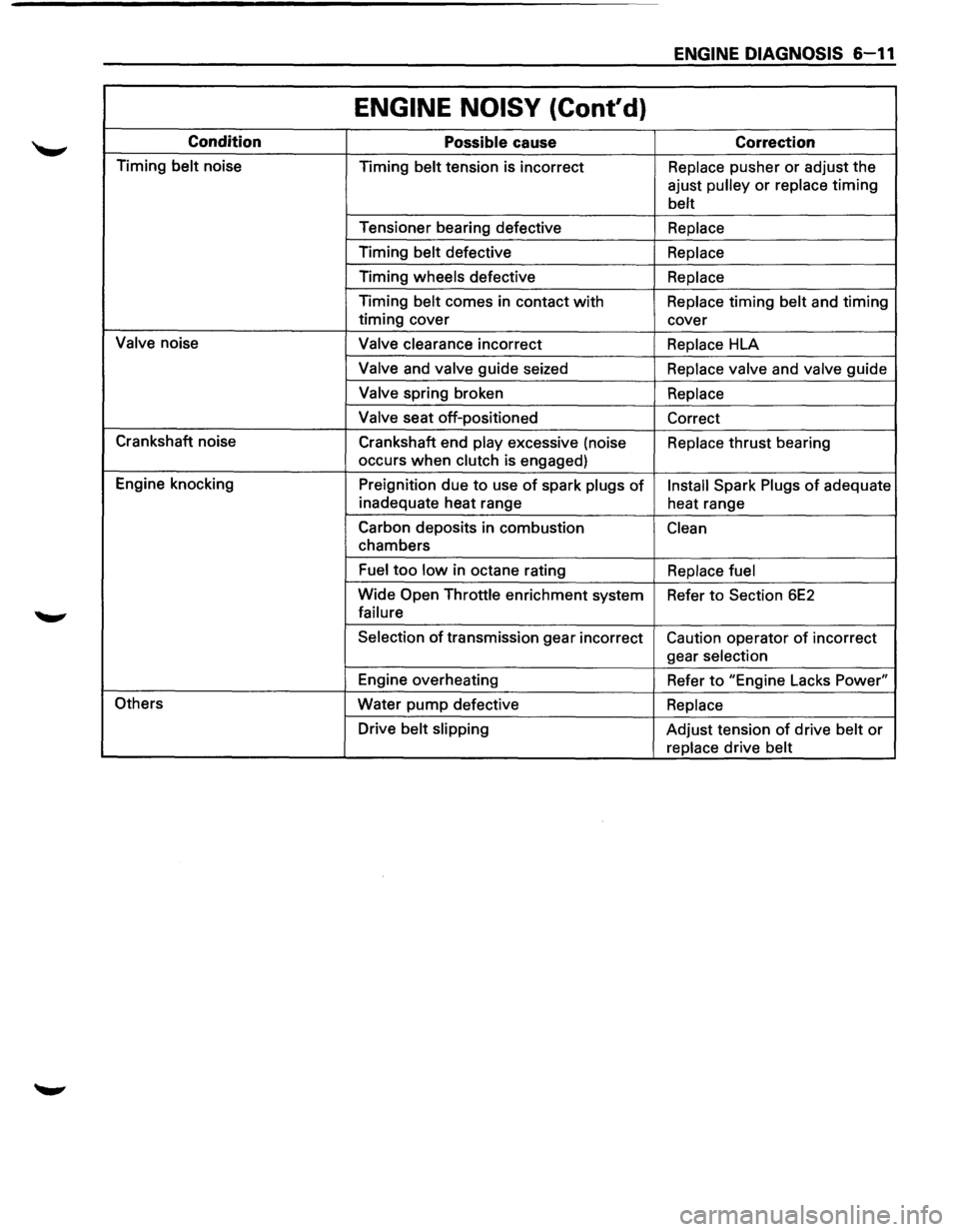
ENGINE NOISY (Cont'd)
Condition Possible cause Correction
Timing belt noise
Timing belt tension is incorrect Replace pusher or adjust the
ajust
pulley or replace timing
belt
Tensioner bearing defective Replace
Timing belt defective Replace
Timing wheels defective Replace
Timing belt comes in contact with Replace timing belt and timing
timing cover
cover
Valve noise Valve clearance incorrect Replace HLA
Valve and valve guide seized Replace valve and valve guide
Valve spring broken Replace
Valve
seat off-positioned
Correct
Crankshaft noise
Crankshaft end
play excessive (noise Replace thrust bearing
occurs
when clutch is engaged)
Engine knocking
Preignition due
to use of spark plugs of Install Spark Plugs of adequate
inadequate heat range
heat range
Carbon deposits in combustion
Clean
chambers
Fuel too low in octane rating Replace fuel
Wide Open Throttle enrichment system
Refer to Section 6E2
failure
Selection
of transmission gear incorrect Caution operator of incorrect
gear
selection
Engine overheating
Refer to "Engine Lacks Power"
Others Water
pump defective Replace
Drive belt slipping Adjust tension of drive belt or
replace drive belt
Page 512 of 1928
6-14 ENGINE DIAGNOSIS
1;:-
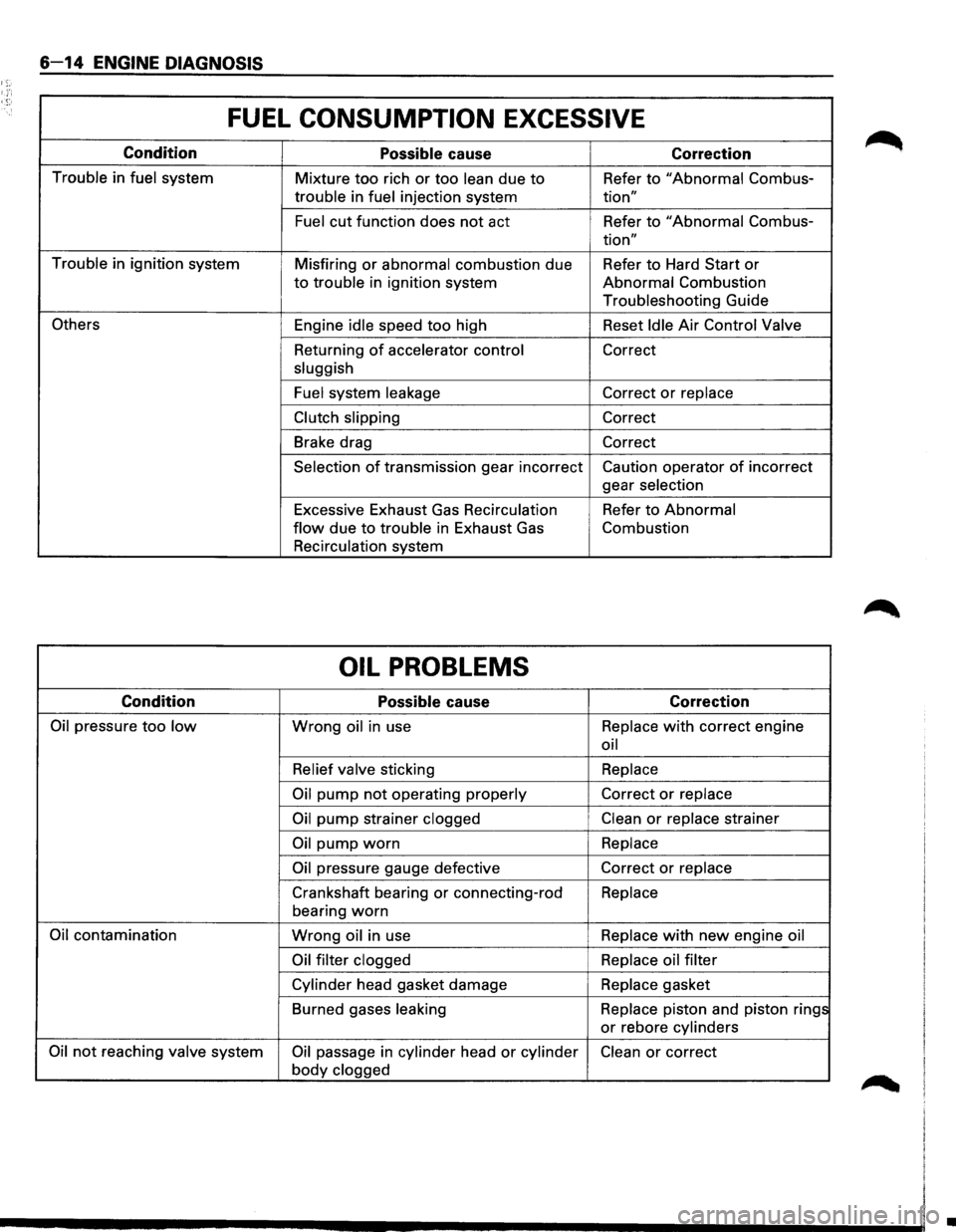
FUEL CONSUMPTION EXCESSIVE
Condition
Possible cause Correction
Trouble in fuel system
Mixture too rich or too lean due to Refer to "Abnormal Combus-
trouble in fuel injection system tion"
Fuel cut function does not act Refer to "Abnormal Combus-
tion"
Trouble in ignition system
Misfiring or abnormal combustion due Refer to Hard Start or
to trouble in ignition system Abnormal Combustion
Troubleshooting Guide
Others Engine idle speed too high Reset Idle Air Control Valve
Returning
of accelerator control Correct
sluggish
Fuel system leakage
Correct or replace
Clutch slipping Correct
Brake drag Correct
Selection of transmission gear incorrect Caution operator of incorrect
gear selection
Excessive Exhaust
Gas Recirculation Refer to Abnormal
flow due to trouble in Exhaust Gas Combustion
Recirculation system
OIL PROBLEMS
Condition
Possible cause Correction
Oil pressure too low Wrong oil in use Replace with correct
engine
oil
Relief valve sticking Replace
Oil pump not operating
properly Correct or replace
Oil pump strainer clogged Clean or replace strainer
Oil pump worn Replace
Oil pressure gauge defective Correct or replace
Crankshaft bearing or connecting-rod Replace
bearing
worn
Oil contamination Wrong oil in use Replace with new engine
oil
Oil filter clogged Replace oil filter
Cylinder head gasket damage Replace
gasket
Burned gases leaking Replace piston and piston rings
or rebore cylinders
Oil not reaching valve system Oil passage in cylinder head or cylinder Clean or correct
body clogged
•
Page 618 of 1928
6A1-60 ENGINE (V6 3.2L DOHC AND SOHC}
4. Timing belt
• See "Timing Belt Removal and Installation".
3. Timing belt cover
2. Crankshaft pulley
~ • Using special tool J-8614-01, hold the
~ crankshaft pulley.
~~~· Tighten center bolt to the specified torque.
Torque
N·m (lb·ft) 167 (123)
1. Engine assembly
• See "Engine Assembly Removal and Instal
lation".
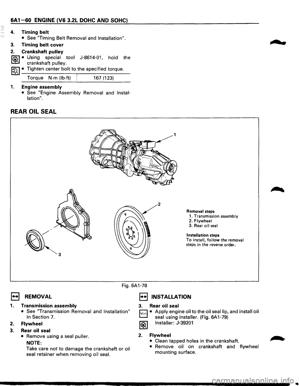
REAR OIL SEAL
Removal steps
1. Transmission assembly
2.
Flywheel 3. Rear oil seal
Installation steps To install, follow the removal
steps in the reverse order.
Fig. 6A1-78
E) REMOVAL
1. Transmission assembly
• See "Transmission Removal and Installation"
in Section 7.
2. Flywheel
3. Rear oil seal
•
Remove using a seal puller.
NOTE:
Take care
not to damage the crankshaft or oil
seal retainer
when removing oil seal.
1••1 INSTALLATION
3. Rear oil seal
C1 • Apply engine oil to the oil seal lip, and install oil
L:::l seal using installer. (Fig. 6A 1-79)
1®1 Installer: J-39201
2. Flywheel
• Clean tapped holes in the crankshaft.
• Remove oil on crankshaft and flywheel
mounting surface.
...
Page 619 of 1928
NOTE:
• Do not reuse the bolts.
•
Do not apply oil or thread lock to the bolts.
~~~ • Tighten bolts to the specified torque.
Torque
N·m (lb·ft) 54 (40)
1. Transmission
• See "Transmission Removal and Installation"
in Section 7.
Fig. 6A1-79
ENGINE ASSEMBL V
ENGINE (V6 3.2L DOHC AND SOHC) 6A 1-61
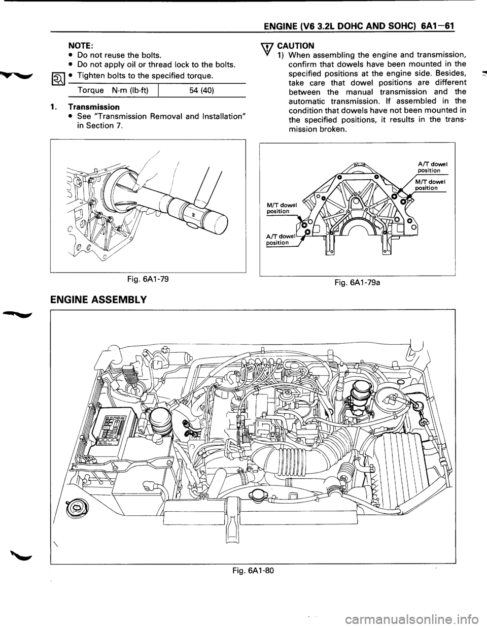
U7 CAUTION
VI 1) When assembling the engine and transmission,
confirm that
dowels have been mounted in the
specified positions at the engine side. Besides,
take care that
dowel positions are different
between the
manual transmission and the
automatic transmission.
If assembled in the
condition that
dowels have not been mounted in
the specified positions,
it results in the trans
mission broken.
M/Tdowel position
AIT dowe I Y~---...rr"lr-'1--' position
Fig. 6A1-79a
A/Tdowel position
Fig. 6A1-80
Page 620 of 1928
'.n
6A1-62 ENGINE (V6 3.2L DOHC AND SOHC)
E) REMOVAL
Preparation: • Disconnect battery ground cable.
• Remove engine hood.
In order to return the hood to the
original position exactly, make
alignment on the hood and hinges
before
removal.
•
Drain radiator coolant.
1. Accelerator cable
• Disconnect from throttle valve and common
chamber.
2. Ventilation hose
3.
Air hose
4. Air cleaner assembly
5. Canister vacuum hose
6. Vacuum booster hose
7. Engine harness connectors
• Disconnect three connectors on canister side.
8. Battery ground cables
• Disconnect two black and white connector
clips
from the power steering pump bracket.
9. Ground cables
• Disconnect two terminals connected to the
battery support and the
front right frame.
1 0. Bonding cable connector
• Disconnect connector on the left side dash
panel.
11. Bonding cable terminal
• Disconnect terminal on the back of left bank.
12. Starter harness connector
• Disconnect from starter.
13. Radiator
• Disconnect upper and lower hoses from the
engine.
• Disconnect coolant reserve tank hose from
radiator.
• Disconnect ATF hose from the pipe. (A/T)
• Remove radiator lower hose clip from the hose
bracket.
• Remove radiator lower fan shroud.
• Remove radiator.
14. Power steering pump drive belt
15. Power steering pump
• Remove two bolts on the bracket, and place the
pump along with piping on the body side.
16. Air Conditioning compressor drive belt
17. Air Conditioning compressor
• Remove fixing bolts and shift aside the
compressor
with piping attached.
18. Heater hoses
• Disconnect two hoses from the engine.
19. ATF pipes
• Disconnect two pipes from right side engine
mount.
20. Transmission assembly
• See "Transmission Removal and Installation"
in Section 7.
21. Left side engine mount
• Support the engine.
• Remove two fixing bolts from engine mount on
chassis side.
22. Right side engine mount
• Remove two fixing bolts from engine mount on
chassis side.
23. Engine assembly
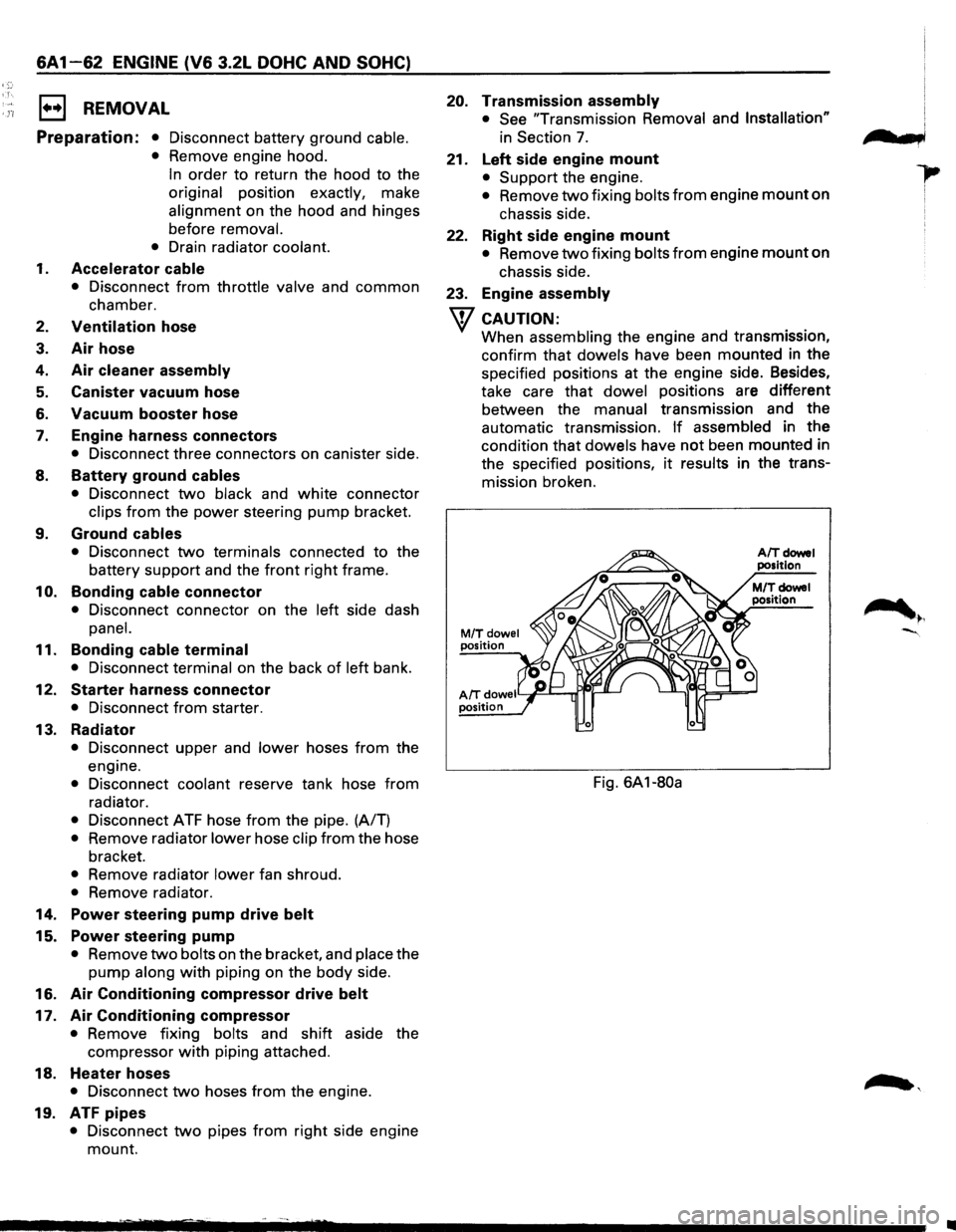
w CAUTION:
When assembling the engine and transmission,
confirm
that dowels have been mounted in the
specified positions at the engine side. Besides,
take care
that dowel positions are different
between the manual transmission and the
automatic transmission.
If assembled in the
condition that dowels have not been mounted in
the specified positions,
it results in the trans
mission broken.
M/Tdowel position
AIT doweiY~--r..ri~-' position
Fig. 6A1-80a
n t b,
•
Page 630 of 1928
68 - 2 ENGINE COOLING
The cooling system is a pressurized Engine Coolant
(EC) forced circulation type which consists of water
pump, thermostat cooling fan, radiator and other
components. The automatic transmission fluid is
cooled by the EC in radiator.
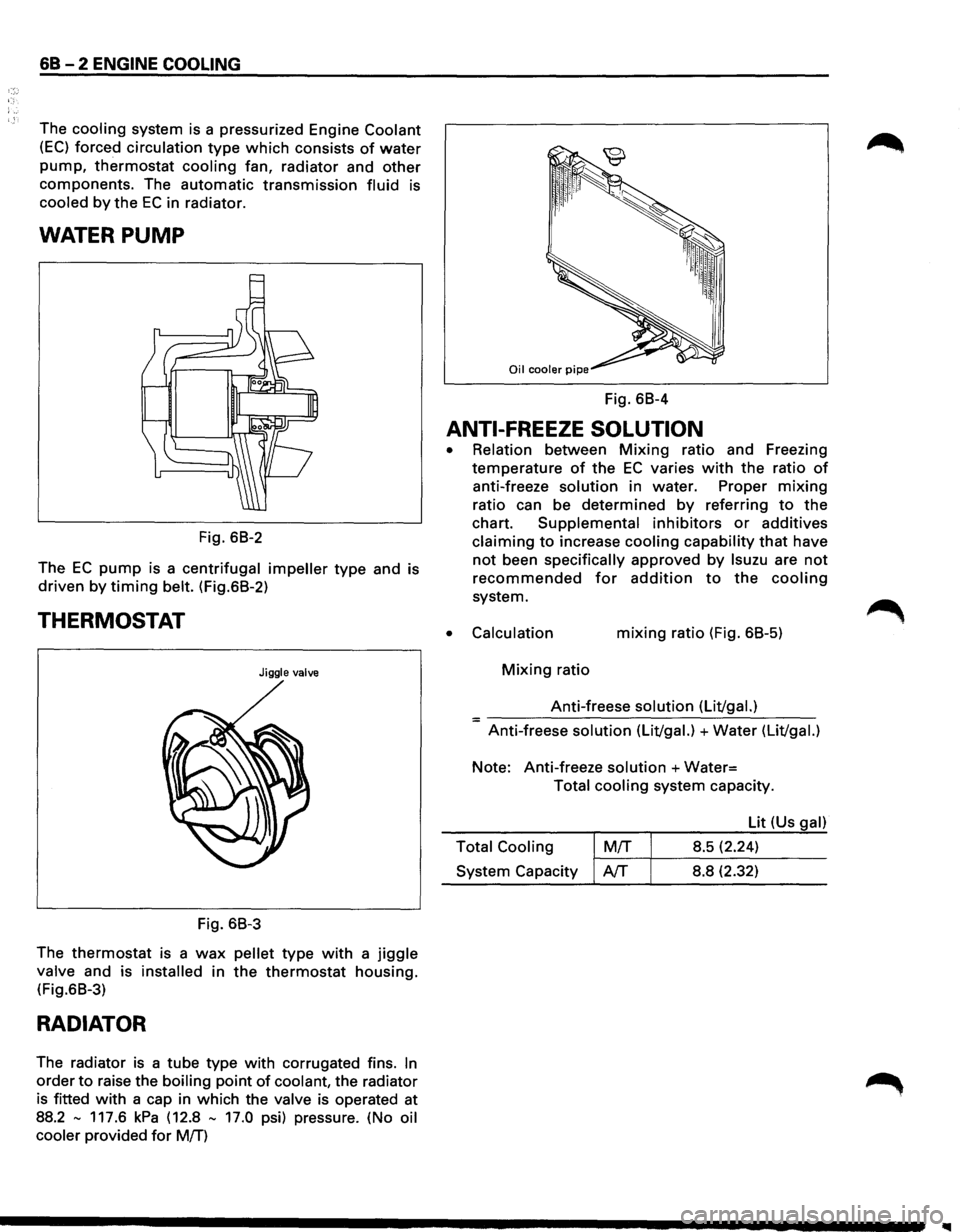
WATER PUMP
Fig. 68-2
The
EC pump is a centrifugal impeller type and is
driven by timing belt. (Fig.68-2)
THERMOSTAT
Jiggle valve
Fig. 68-3
The
thermostat is a wax pellet type with a jiggle
valve and is installed in the thermostat housing.
(Fig.68-3)
RADIATOR
The radiator is a tube type with corrugated fins. In
order to raise the boiling point of coolant, the radiator
is fitted
with a cap in which the valve is operated at
88.2
-117.6 kPa (12.8 - 17.0 psi) pressure. (No oil
cooler
provided for M!f)
Fig. 68-4
ANTI-FREEZE SOLUTION
•
•
Relation between Mixing ratio and Freezing
temperature
of the EC varies with the ratio of
anti-freeze solution in water. Proper mixing
ratio can be determined by referring to the
chart. Supplemental inhibitors or additives
claiming to increase cooling capability that have
not been specifically approved by lsuzu are not
recommended for addition to the cooling
system.
Calculation mixing ratio (Fig. 68-5)
Mixing ratio
Anti-freese
solution (Lit/gal.) =-----------------Anti-freese solution (Lit/gal.) +Water (Lit/gal.)
Note: Anti-freeze solution +Water=
Total cooling system capacity.
Lit (Us
gal)
Total Cooling
M!f 8.5 (2.24) ~-~~--------System Capacity AfT 8.8 (2.32)
Page 632 of 1928
68 - 4 ENGINE COOLING
ON-VEHICLE SERVICE
DRAINING AND REFILLING COOLING
SYSTEM
Before draining the cooling system, inspect the sys
tem and perform any necessary service to ensure that
it is clean, does not leak and is in proper working
order. The Engine Coolant (EC) level should be be
tween the "MIN" and "MAX" lines of reserve tank
when the engine is cold. If low, check for leakage and
add
EC up to the "MAX" line. There should not be any
excessive deposit of rust or scales around the radiator
cap
or radiator filler hole, and the EC should also be
free
from oil. Replace the EC if excessively dirty.
1. Completely drain the cooling system by opening
the drain petcock at the bottom of the radiator.
2. Remove the radiator cap.
W WARNING
To avoid the danger of being burned, do not
remove the cap while the engine and radiator
are still hot. Scalding fluid and steam can be
blown out under pressure.
3. Disconnect all hoses from the EC reserve tank.
Scrub and clean the inside of the reserve tank with
soap and water. Flush it well with clean water,
then drain it. Install the reserve tank and hoses.
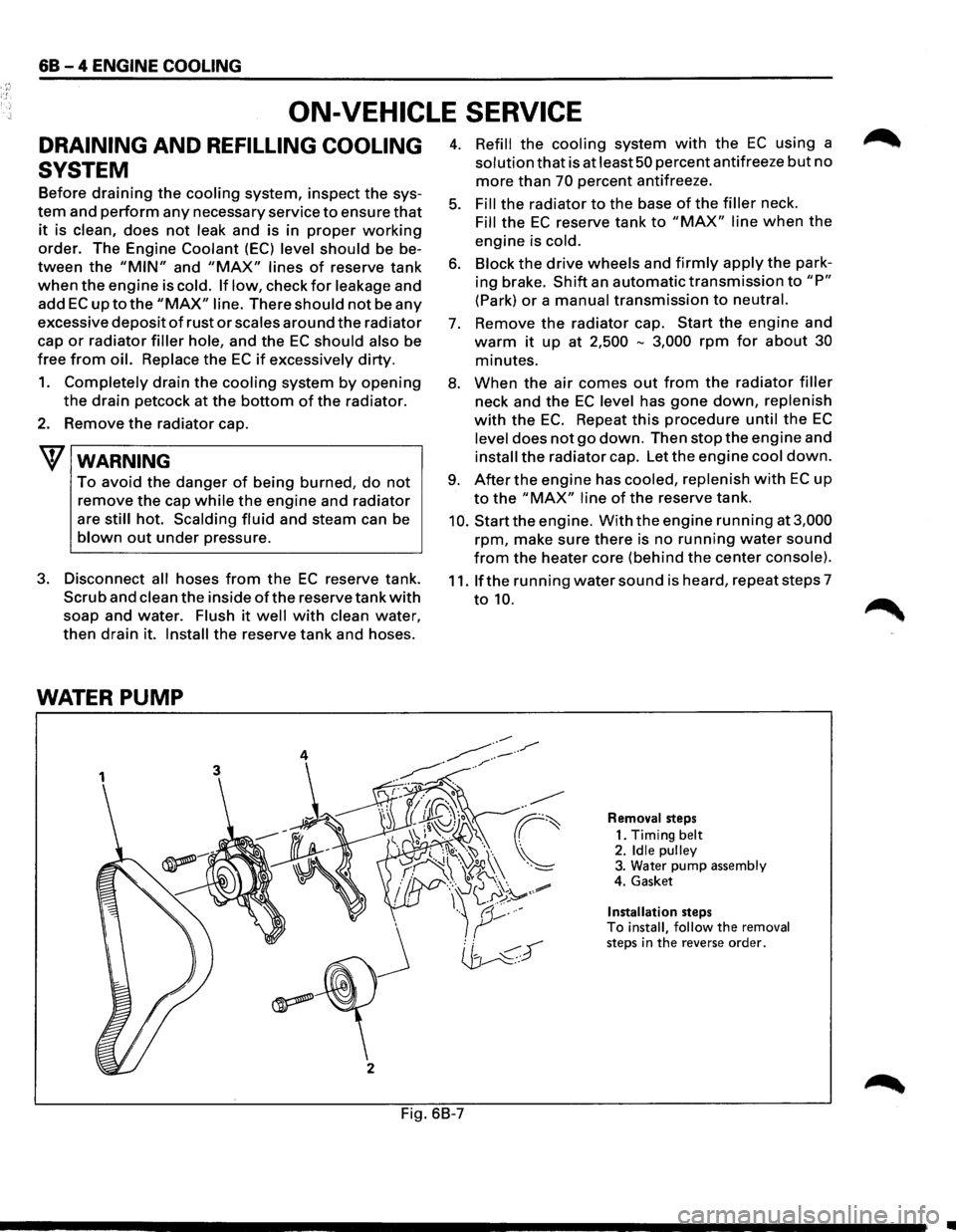
WATER PUMP
3
j
2
4. Refill the cooling system with the EC using a
solution that is at least 50 percent antifreeze but no
more than 70 percent antifreeze.
5. Fill the radiator to the base of the filler neck.
Fill the EC reserve tank to "MAX" line when the
engine is cold.
6. Block the drive wheels and firmly apply the park
ing brake.
Shift an automatic transmission to "P"
(Park) or a manual transmission to neutral.
7. Remove the radiator cap. Start the engine and
warm it up at 2,500 -3,000 rpm for about 30
minutes.
8. When the air comes out from the radiator filler
neck and the EC level has gone down, replenish
with the EC. Repeat this procedure until the EC
level does not go down. Then stop the engine and
install the radiator cap. Let the engine cool down.
9. After the engine has cooled, replenish with EC up
to the "MAX" line of the reserve tank.
10. Start the engine. With the engine running at 3,000
rpm, make sure there is no running water sound
from the heater core (behind the center console).
11. If the running water sound is heard, repeat steps 7
to 10.
Removal steps
1. Timing
belt 2. Idle pulley 3. Water pump assembly
4. Gasket
Installation steps To install, follow the removal steps in the reverse order.
Fig. 6B-7
•
Page 652 of 1928
6C -10 ENGINE FUEL
Adjustment of pedal stroke
Manual Transmission:
• Rotate counterclockwise to loosen the stopper
bolt sufficiently.
• Fully depress the pedal and hold it there hand.
Next, rotate the stopper bolt until it hits the
stopper of pedal bracket. Then, lock the stopper
bolt there.
Automatic Transmission:
• Rotate counterclockwise to loosen the kickdown
switch sufficiently.
• Fully depress the pedal and hold it there hand.
Rotate
the switch clockwise and then rotate
further by 1/2 turn from the position where the
switch clicks. Lock the switch there.
• Step on the accelerator pedal and make sure that
you can hear clicking sound at the full stroke
position.
AIR CLEANER FILTER
EJ REMOVAL
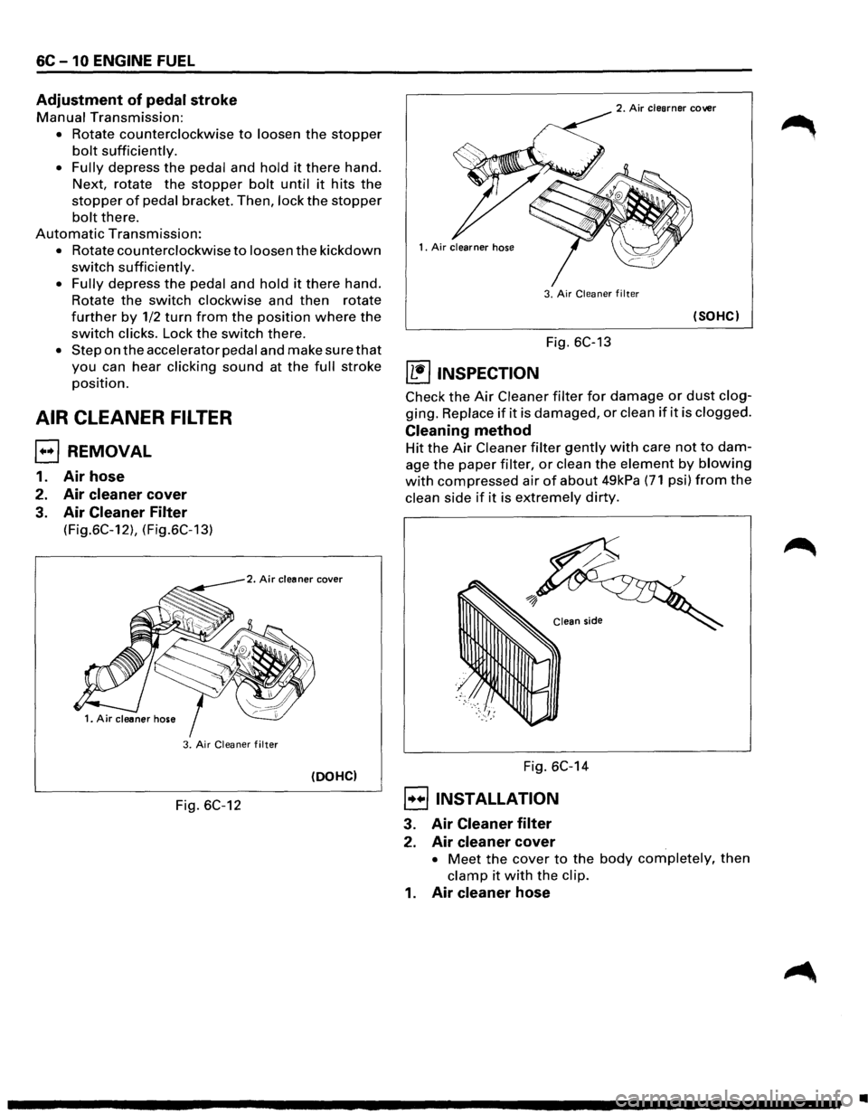
1. Air hose
2. Air cleaner cover
3. Air Cleaner Filter
(Fig.6C-12), (Fig.6C-13)
2. Air cleaner cover
3. Air Cleaner filter
(DOHC)
Fig. 6C-12
2. Air clearner cover
3.
Air Cleaner filter
(SOHC)
Fig. 6C-13
~ INSPECTION
Check the Air Cleaner filter for damage or dust clog
ging. Replace if it is damaged, or clean if it is clogged.
Cleaning method
Hit the Air Cleaner filter gently with care not to dam
age the paper filter, or clean the element by blowing
with compressed air of about 49kPa (71 psi) from the
clean side if it is extremely dirty.
Fig. 6C-14
8 INSTALLATION
3. Air Cleaner filter
2. Air cleaner cover
• Meet the cover to the body completely, then
clamp it with the clip.
1. Air cleaner hose
•