wheel torque ISUZU TROOPER 1995 Manual Online
[x] Cancel search | Manufacturer: ISUZU, Model Year: 1995, Model line: TROOPER, Model: ISUZU TROOPER 1995Pages: 1928
Page 1750 of 1928
9J-126 Supplemental Restraint System
INSTALLATION
1. Install the steering wheel and align the setting ~
marks.
2. Tighten the steering fixing nut to the specified
torque.
Torque : 34N·m(25 lb·ft.).
3. Connect horn lead connector.
4. Connect inflator module to 2-way yellow wiring
harness connector.
5. Install inflator module into steering wheel and
torque fasteners.
Torque: 8N·m(69 lb·in.)
6. Enable the SRS (Refer to "Enabling the SRS" in
this section.).
•
Page 1752 of 1928
9J-128 Supplemental Restraint System
12. Remove steering column cover.
13. Disconnect the wiring harness connectors ~
located base of steering column.
14. Remove the combination switch assembly with
SRScoil.
NOTE: SRS
coil is a part of combination switch
assembly, which
cannot be replaced individually.
Therefore, be sure not to remove the
SRS coil from the
combination switch assembly.
INSTALLATION
1. Install the combination switch assembly with
SRScoil.
2. Connect the wiring harness connector located In
base of steering column.
3. Turn the SRS coil clockwise to full, return about
3 turns and align the neutral mark.
CAUTION: WHEN TURNING THE SRS COIL
CLOCKWISE TO FULL, STOP TURNING IF
RESISTANCE IS FELT. FORCED FURTHER
TURNING MAY CAUSE DAMAGE TO THE CABLE IN
THE SRS COIL.
4. Install steering column cover.
CAUTION: WHEN INSTALLING THE STEERING
COLUMN COVER, BE SURE TO WIRE (THROUGH ~
EACH HARNESS) AS ILLUSTRATED SO THAT THE
HARNESSES OF STARTER SWITCH,COMBINATION
SWITCH
AND SRS COIL MAY NOT CATCH WIRING.
5. Install the steering wheel and align the setting
marks.
6. Tighten the steering fixing nut to the specified
torque.
Torque : 34N·m(25 lb·ft.).
7. Connect horn lead connector.
8. Connect inflator module to 2-way yellow wiring
harness connector.
9. Install inflator module into steering wheel and
torque fasteners.
NOTE: Always replace inflator module {Air Bag)
fasteners with new fasteners. Never reuse old fasteners.
Torque: 8N·m(69 lb·ln.)
10. Install the steering lower cover and engine hood
opening lever.
11. Install front console assembly and connect the
wiring harness connector.
12. Install the transmission knob{for M/T) and
transfer control knob. ~
13. Enable the SRS (Refer to "Enabling the SRS" in
this section.).
•
Page 1754 of 1928
9J .. 130 Supplemental Restraint System
CAUTION: NEVER APPLY FORCE TO THE
STEERING WHEEL IN DIRECTION OF THE SHAFT
BY USING A HAMMER OR OTHER I~PACT TOOLS
IN AN ATTEMPT TO REMOVE THE STEERING
WHEEL. THE STEERING SHAFT IS DESIGNED AS
AN ENERGY ABSORBING UNIT.
12. Remove steering column cover.
13.
Disconne~t the wiring harness connectors
located base of steering column.
14. Remove the combination switch assembly with
SRScoil.
NOTE: SRS
coil is a part of combination switch
assembly,
which cannot be replaced individually.
Therefore, be sure not to remove the SRS coil from the
combination switch assembly.
15. Remove snap ring.
16. Remove cushion rubber.
17. Disconnect shift
lock cable(For AfT)
18. Disconnect the starter switch harness connector.
Located base of steering column.
19. Remove steering
lock cylinder assembly.
20. Apply a setting mark across the universal joint
and steering shaft to reassemble the parts
in ~
their original position. ~
21. Remove steering column assembly.
NOTE: A setting mark can be easily made if the shaft
is with draw a little by loosening the steering shaft
universal joint.
INSTALLATION
1. Install steering column assembly and align the
setting marks on the universal joint and steering
shaft made during removal.
2. Tighten the steering column fixing bolts( dash
panel side) to the specified torque.
Torque:
19N·m(14 lb·ft.).
3. Tighten the steering column fixing bolts( Pedal
bracket) to the specified torque.
Torque:
17N·m(13 lb·ft.).
4. Tighten the universal joint to the specified
torque.
Torque:
25N·m(181b·ft.).
5. Install steering lock cylinder assembly.
6. Connect shift lock cable(For AfT)
7. Install cushion rubber.
8. Install snap ring.
9. Install the combination switch assembly with
SRScoil.
Page 1755 of 1928
1 o. Connect the wiring harness connector located
base of steering column.
11. Turn the SRS coil clockwise to full, return about
3 turns and align the neutral mark.
CAUTION: WHEN TURNING THE SRS COIL
CLOCKWISE TO FULL, STOP TURNING IF
RESISTANCE IS FELT. FORCED FURTHER
TURNING MAY CAUSE DAMAGE TO THE CABLE IN
THE SRS COIL.
12. Install steering column cover.
CAUTION: WHEN INSTALLING THE STEERING
COLUMN COVER,
BE SURE TO WIRE {THROUGH
EACH HARNESS) AS ILLUSTRATED SO THAT THE
HARNESSES OF STARTER SWITCH,COMBINATION
SWITCH
AND SRS COIL MAY NOT CATCH WIRING.
13. Install the steering wheel and align the setting
marks.
14. Tighten the steering fixing nut to the specified
torque.
Torque: 34N·m(25 lb·ft.).
15. Connect horn lead connecor.
16. Connect inflator module to
2-way yellow wiring
harness connector.
17.
Install inflator module into steering wheel and
torque fasteners.
Torque: 8N·m(69 lb-in.)
18. Install the steering lower cover and engine hood
opening lever.
19.
Install front console assembly and connect the
wiring harness connector.
20.
Install the transmission knob(for M/T) and
transfer control knob.
21. Enable the
SRS (Refer to "Enabling the SRS" in
this section.).
Supplemental Restraint System 9J-131
Page 1845 of 1928
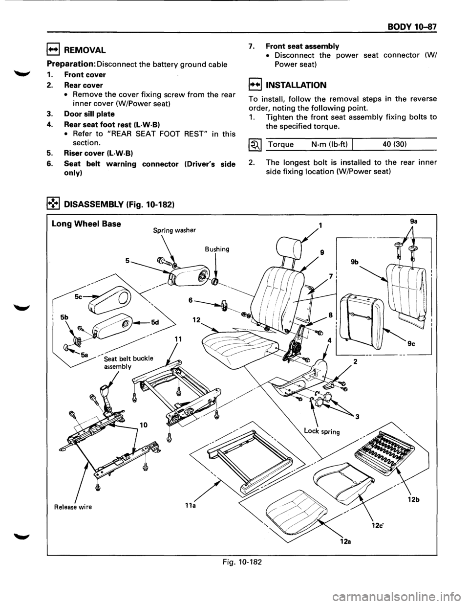
1++1 REMOVAL
Preparation:
Disconnect the battery ground cable
1. Front cover
2. Rear cover
• Remove the cover fixing screw from the rear
inner cover (W/Power seat)
3. Door sill plate
4. Rear seat foot rest (l·W·B)
• Refer to "REAR SEAT FOOT REST" in this
section.
5. Riser cover (L·W·B)
6. Seat belt warning connector (Driver's side
only)
1•!•1 DISASSEMBLY (Fig. 10-182)
Long Wheel Base Spring washer
Bushing
5
Release wire
BODY 10-87
7. Front seat assembly
•
Disconnect the power seat connector (W/
Power seat)
I++IINSTALLATION
To install, follow the removal steps in the reverse
order,
noting the following point.
1. Tighten the front seat assembly fixing bolts to
the specified torque.
~~~ Torque N-m (lb·ft) 40 (30)
2. The longest bolt is installed to the rear inner
side fixing location (W/Power seat)
9a
Fig. 10-182
Page 1861 of 1928
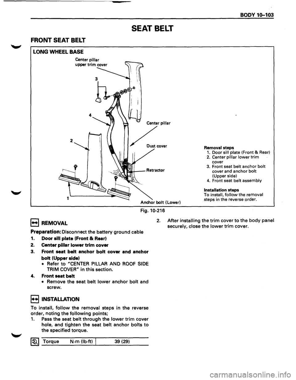
FRONT SEAT BELT
LONG WHEEL BASE
2
1
Center pillar
upper trim cover
SEAT BELT
Center pillar
~ .....
Anchor bolt (Lower)
Fig. 10-216
BODY 1Q-103
Removal steps 1. Door sill plate (Front & Rear)
2. Center pillar lower trim cover 3. Front seat belt anchor bolt cover and anchor bolt (Upper side) 4. Front seat belt assembly
Installation
steps
To install, follow the removal
steps in the reverse order.
B REMOVAL 2. After installing the trim cover to the body panel
securely, close
the lower trim cover.
Preparation: Disconnect the battery ground cable
1. Door sill plate (Front & Rear)
2. Center pillar lower trim cover
3. Front seat belt anchor bolt cover and anchor
bolt (Upper side)
• Refer to "CENTER PILLAR AND ROOF SIDE
TRIM COVER" in this section.
4. Front seat belt
• Remove the seat belt lower anchor bolt and
screw.
I••IINSTALLATION
To install, follow the removal steps in the reverse
order, noting the
following points;
1. Pass the seat belt through the lower trim cover
hole, and tighten the seat belt anchor bolts to
the specified torque.
~~~ Torque N·m (lb·ft) I 39 (29)
Page 1862 of 1928
----
10-104 BODY
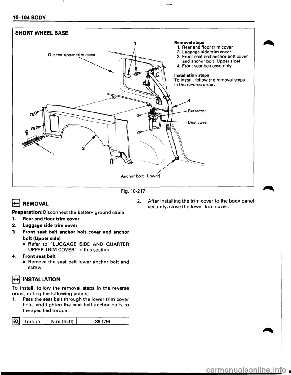
SHORT
WHEEL BASE
3 Removal steps 1. Rear end floor trim cover 2. Luggage side trim cover 3. Front seat belt anchor bolt cover
and anchor bolt (Upper side)
4. Front seat belt assembly
Installation steps
To install, follow the removal steps
in the reverse order.
4
Retractor
Anchor bolt (Lower)
Fig. 10-217
1++1 REMOVAL
Preparation: Disconnect the battery ground cable
1. Rear end floor trim cover
2. Luggage side
trim cover
3.
Front seat belt anchor bolt cover and anchor
bolt (Upper side)
• Refer to "LUGGAGE SIDE AND QUARTER
UPPER TRIM COVER" in this section.
4. Front seat belt
• Remove the seat belt lower anchor bolt and
screw.
I••IINSTALLATION
To install, follow the removal steps in the reverse
order,
noting the following points;
1. Pass the seat belt through the lower trim cover
hole, and tighten the seat belt anchor bolts to
the specified torque.
~~~ Torque N-m (lb·ft) 39 (29)
2. After installing the trim cover to the body panel
securely, close
the lower trim cover.
•
Page 1864 of 1928
10-106 BODY
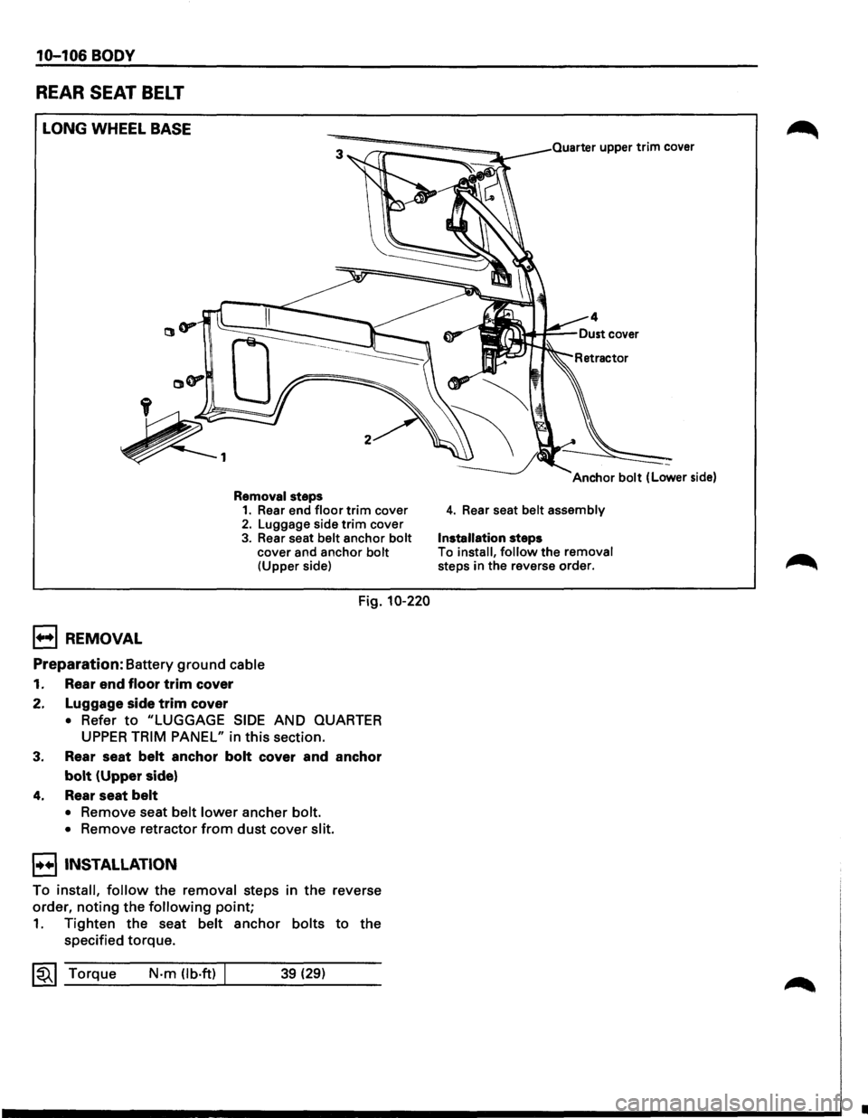
REAR SEAT BELT
LONG WHEEL BASE
B REMOVAL
Removal steps 1. Rear end floor trim cover 2. Luggage side trim cover
3. Rear seat belt anchor bolt cover and anchor bolt (Upper side)
Fig. 10-220
Preparation: Battery ground cable
1. Rear end floor trim cover
2. Luggage side
trim cover
• Refer to "LUGGAGE SIDE AND QUARTER
UPPER TRIM PANEL" in this section.
3. Rear seat belt anchor bolt cover and anchor
bolt (Upper side)
4. Rear seat belt
• Remove seat belt lower ancher bolt.
•
Remove retractor from dust cover slit.
I••IINSTALLATION
To install, follow the removal steps in the reverse
order,
noting the following point;
1. Tighten the seat belt anchor bolts to the
specified torque.
~~~ Torque N·m (lb.ft) 39 (29)
Quarter upper trim cover
4. Rear seat belt assembly
Installation steps
To install, follow the removal steps in the reverse order.
•