wheel torque ISUZU TROOPER 1995 Repair Manual
[x] Cancel search | Manufacturer: ISUZU, Model Year: 1995, Model line: TROOPER, Model: ISUZU TROOPER 1995Pages: 1928
Page 485 of 1928
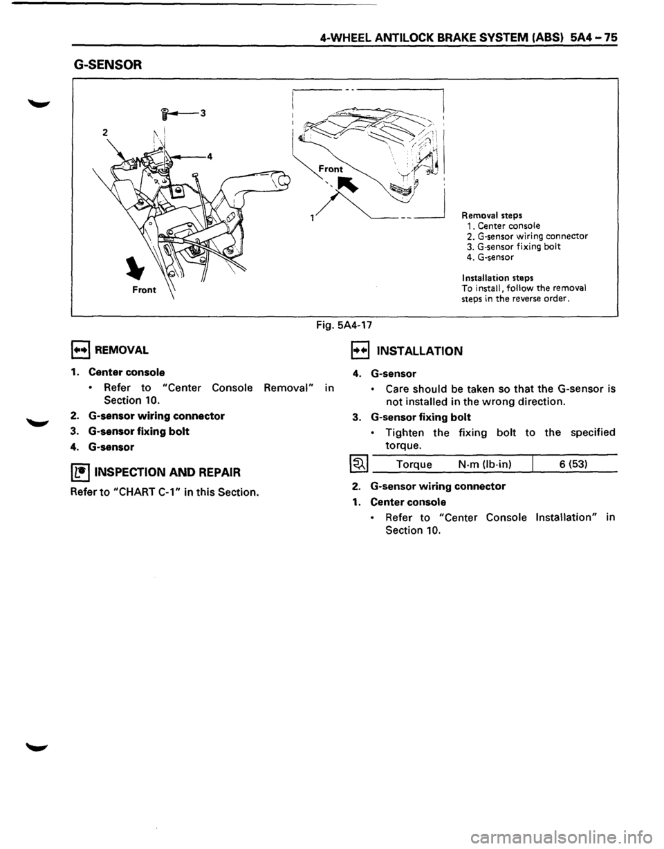
G-SENSOR
, .... ,REMOVAL
1. Center console
4-WHEEL ANTILOCK BRAKE SYSTEM (ABS) 5A4-75
Fig. 5A4-17
Removal steps 1. Center console 2. G-sensor wiring connector 3. G·sensor fixing bolt 4. G-sensor
Installation steps To install, follow the removal steps in the reverse order.
, .. .,, INSTALLATION
4. G-sensor
• Refer to "Center Console Removal" in • Care should be taken so that the G-sensor is
not installed in the wrong direction.
Section 10.
2. G-sensor wiring connector
3. G-sensor fixing bolt
4. G-sensor
IL•ItNSPECTION AND REPAIR
Refer to "CHART
C-1" in this Section.
3. G-sensor fixing bolt
• Tighten the fixing bolt to the specified
torque.
I~I ____ T_o_rq~u~e ____ N~·-m~(lb_·_in~)--~ ___ 6_(_53~) __ __
2. G-sensor wiring connector
1. Center console
• Refer to "Center Console Installation" in
Section
10.
Page 487 of 1928
I••! INSTALLATION
5. Speed sensor
4-WHEEL ANTILOCK BRAKE SYSTEM (ABS) 5A4-77
,.....,. • Take care not to hit the speed sensor pole
piece during installation.
4. Speed sensor fixing bolt
• Tighten the fixing bolt to the specified
torque.
1~1 Torque N·m (lb·in) 8 (69)
3. Speed sensor cable fixing bolt (lower side)
• Tighten the fixing bolt to the specified
torque.
~~~ Torque N·m (lb-ft) 24 (18)
2. Speed sensor cable fixing bolt (Upper side)
• Tighten
torque.
1~1 Torque the
fixing
bolt to the specified
N-m (lb·in) 6 (52)
• Confirm that a white line marked on the
cable is not twisted when connecting the
speed sensor
cable.
1. Speed sensor connector
Page 488 of 1928
5A4-78 4-WHEEL ANTILOCK BRAKE SYSTEM (ABS)
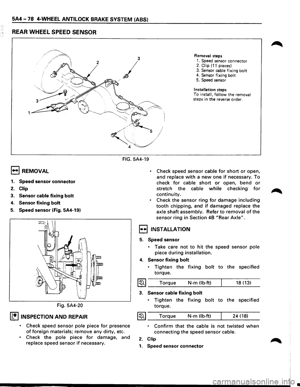
REAR WHEEL SPEED SENSOR
3 Removal steps
2
/
1. Speed sensor connector 2. Clip (11 pieces)
3.
Sensor cable fixing bolt 4. Sensor fixing bolt 5. Speed sensor
j
/
Installation steps
To
install, follow the removal
steps in the reverse order.
FIG. 5A4-19
1+•1 REMOVAL
1. Speed sensor connector
2. Clip
3. Sensor cable fixing bolt
4. Sensor fixing bolt
5. Speed sensor (Fig. 5A4-19)
Fig.
5A4-20
IL•ItNSPECTION AND REPAIR
• Check speed sensor pole piece for presence
of foreign materials; remove any dirty, etc.
• Check the pole piece for damage, and
replace speed sensor if necessary.
• Check speed sensor cable for short or open,
and
replace with a new one if necessary. To
check
for cable short or open, bend or
stretch the cable while checking for
continuity.
• Check the sensor ring for damage including
tooth chipping, and if damaged replace the
axle shaft assembly. Refer to removal of the
sensor ring in
Section 48 "Rear Axle".
,,..,,INSTALLATION
5. Speed sensor
• Take care not to hit the speed sensor pole
piece during installation.
4. Sensor fixing bolt
• Tighten the fixing bolt to the specified
torque.
I~I ____ T_o_rq~u_e ____ N __ ·m __ O_b·_ft_) __ ~ ____ 18_(_1_3_) __
3. Sensor cable fixing bolt
• Tighten the fixing bolt to the specified
torque.
~~~ Torque N·m (lb.ft) 24 (18)
• Confirm that the cable is not twisted when
connecting the speed sensor cable.
2. Clip
1. Speed sensor connector
•
Page 491 of 1928
PARKING BRAKES 5C-1
SECTION 5C
PARKING BRAKES
'\f7 CAUTION:
Yf All brake attaching fasteners are an important attaching part in that they could affect performance of vital
parts and systems, and/or could result in major repair expense. They must be replaced with one ofthe same
part number
or with and equivalent part if replacement becomes necessary. Do not use replacement parts of
lesser quality or substitute design. Torque values must be used as specified during reassembly to assure
proper retention
of these parts.
CONTENTS
General Description ..................... 5C-1
Operation . . . . . . . . . . . . . . . . . . . . . . . . . . . . . 5C-2
On-Vehicle Service
..................... 5C-3
Parking Brake Lever Replacement . .
. . . . .
5C-3
Parking Brake Front Cable . .
. . . . . . . . . . .
5C-4
Parking Brake Rear Cable . .
. . . . . . . . . . . .
5C-5
Parking Brake Lining Inspection ......... 5C-6
Parking Brake Rotor (Drum) Inspection ... 5C-6
Parking Brake Adjustment .............. 5C-7
Main Data and Specifications ............. 5C-8
General
Specifications ................. 5C-8
Torque Specifications ................. 5C-8
GENERAL DESCRIPTION
Pulling up the parking brake lever by hand will set the
parking brake.
Once pulled up, the lever is held by a
ratchet type
lock until it is released. The position of the
lever is transmitted through cable/lever systems to the
rear
wheels. These parts are designed to obtain
sufficient braking force
when parking on slopes. When
the parking brake is set,
or when the ignition SW is in
the
"ON" position, the brake warning light illuminates.
The rear wheel parking brake is a duo-servo brake
(mechanical inside expansion type) built in to the rear
disc brake. Parking brake adjustment is made through
the adjusting
hole (bored through back plate). Parking
brake
lever stroke should be adjusted to 6 or 7
notches. Refer
to "Parking Brake Adjustment" in
this Section.
Page 496 of 1928
5C-6 PARKING BRAKES
1••1 INSTALLATION
15. Rear cable
hl • Apply grease (BESCO L-2 or equivalent) to the
D connecting portion of the rear cable and
equalizer.
14. Equalizer
13. Back plate
12. Adjust nut
• Tighten the adjust nut to the specified torque.
1~1 Torque N-m (lb-in) I 6 (52)
• To adjust the parking brake, refer to "Parking
Brake Adjustment" in this Section.
11,10, 9. Clip
~~~ Torque N·m (lb·in) I 6 (52)
8. Cable fixing bolt
• Tighten the cable fixing bolt to the specified
torque.
~~~ Torque N·m (lb·in) 6 (52)
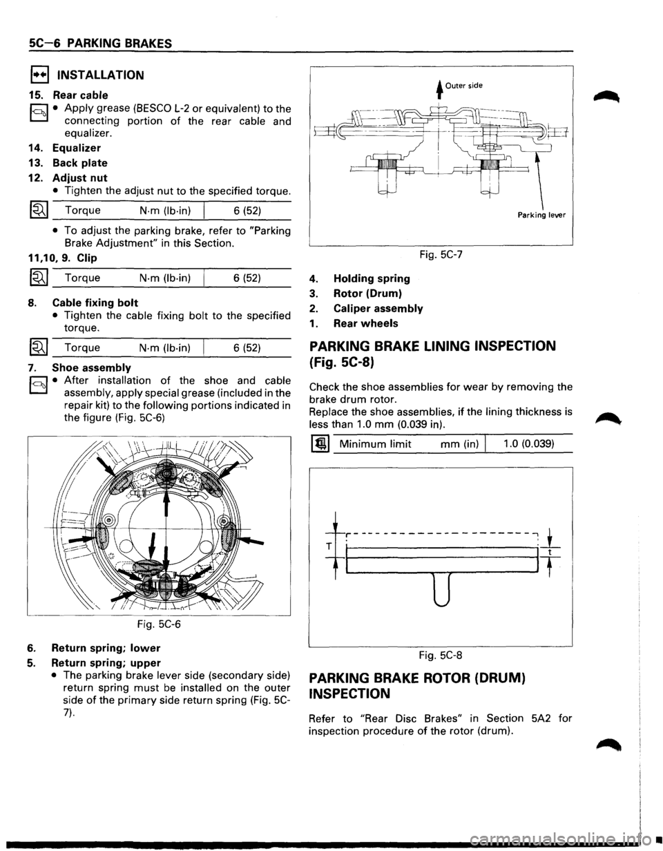
7. Shoe assembly
h1 • After installation of the shoe and cable
D assembly, apply special grease (included in the
repair kit)
to the following portions indicated in
the figure (Fig.
5C-6)
Fig. 5C-6
6. Return spring; lower
5. Return spring; upper
• The parking brake lever side (secondary side)
return spring
must be installed on the outer
side
of the primary side return spring (Fig. 5C-
7).
+Outer side
Fig. 5C-7
4. Holding spring
3. Rotor (Drum)
2. Caliper assembly
1. Rear wheels
Parking lever
PARKING BRAKE LINING INSPECTION
(Fig. SC-8)
Check the shoe assemblies for wear by removing the
brake
drum rotor.
Replace the shoe assemblies, if the lining thickness is
less than 1.0 mm (0.039 in).
1@1 Minimum limit mm (in) J 1.0 (0.039)
-1---r-----------------------,_1_ . '
T I It
u
Fig. 5C-8
PARKING BRAKE ROTOR (DRUM)
INSPECTION
Refer to "Rear Disc Brakes" in Section 5A2 for
inspection procedure
of the rotor (drum).
•
Page 544 of 1928
6A-28 GENERAL ENGINE MECHANICAL
Fig. 6A-80
/
Fig. 6A-81
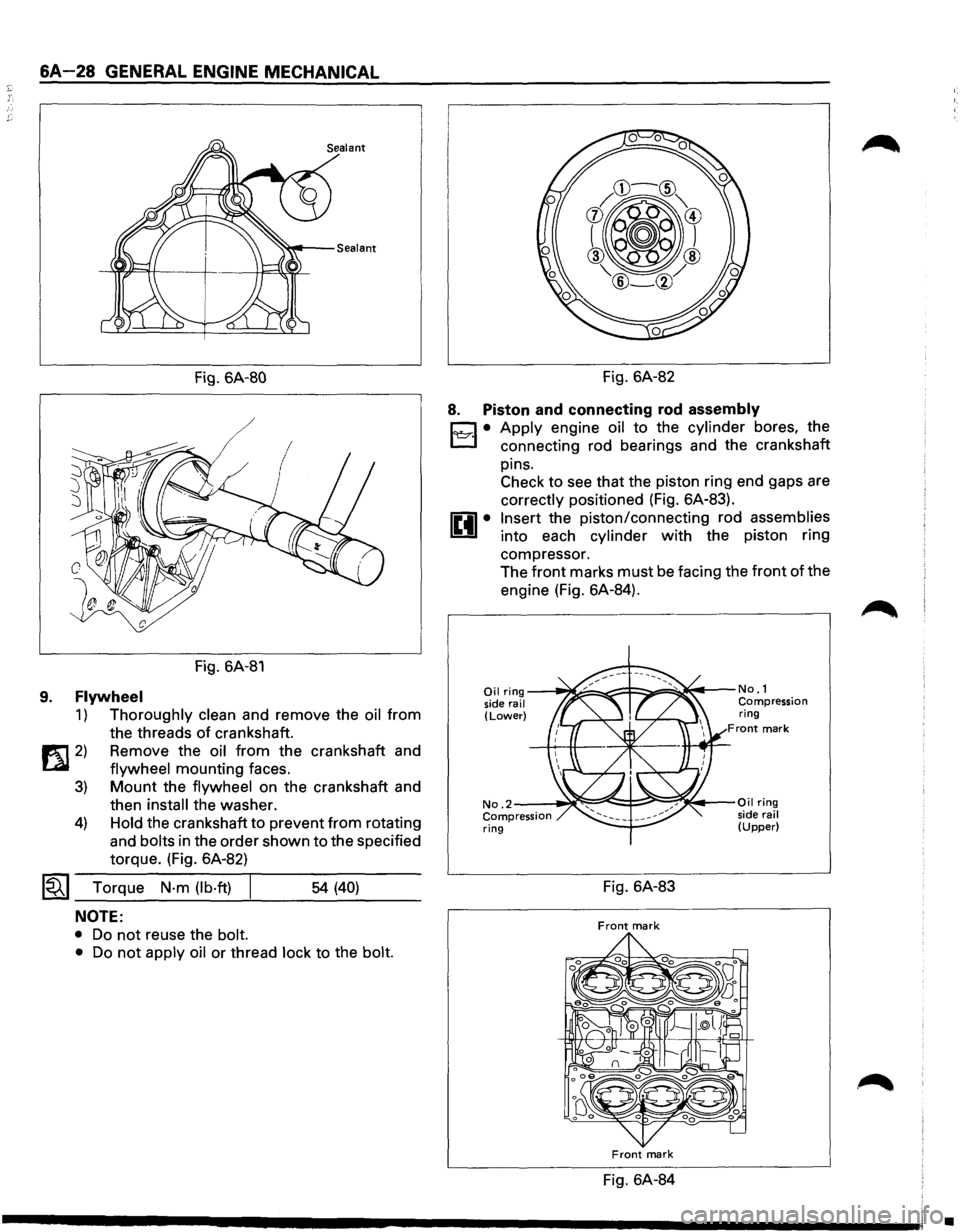
9. Flywheel
1) Thoroughly clean and remove the oil from
the threads
of crankshaft.
1!t1 2) Remove the oil from the crankshaft and
LQI flywheel mounting faces.
3) Mount the flywheel on the crankshaft and
then
install the washer.
4) Hold the crankshaft to prevent from rotating
and
bolts in the order shown to the specified
torque. (Fig. 6A-82)
~~~ Torque N·m (lb·ft) I ___ ___,_ ___ _ 54 (40)
NOTE:
• Do not reuse the bolt.
•
Do not apply oil or thread lock to the bolt.
Fig. 6A-82
8. Piston and connecting rod assembly
D • Apply engine oil to the cylinder bores, the
l:J connecting rod bearings and the crankshaft
pins. Check to see that the piston ring end gaps are
correctly positioned (Fig. 6A-83).
Insert the piston/connecting rod assemblies
into each cylinder with the piston ring
compressor. The
front marks must be facing the front of the
engine (Fig. 6A-84).
Oil ring ---~====-~::F::::::.===~~t---No. 1
side rail Compression (Lower) ring Front mark
No .2--~~:::::=:e!::::!-;::::!!;~~·-Oil ring
Compression side rail ring (Upper)
Fig. 6A-83
Front mark
Front mark
Fig. 6A-84
•
Page 555 of 1928
1,.!.,1 REASSEMBLY
14. Cylinder block
13. Crankshaft
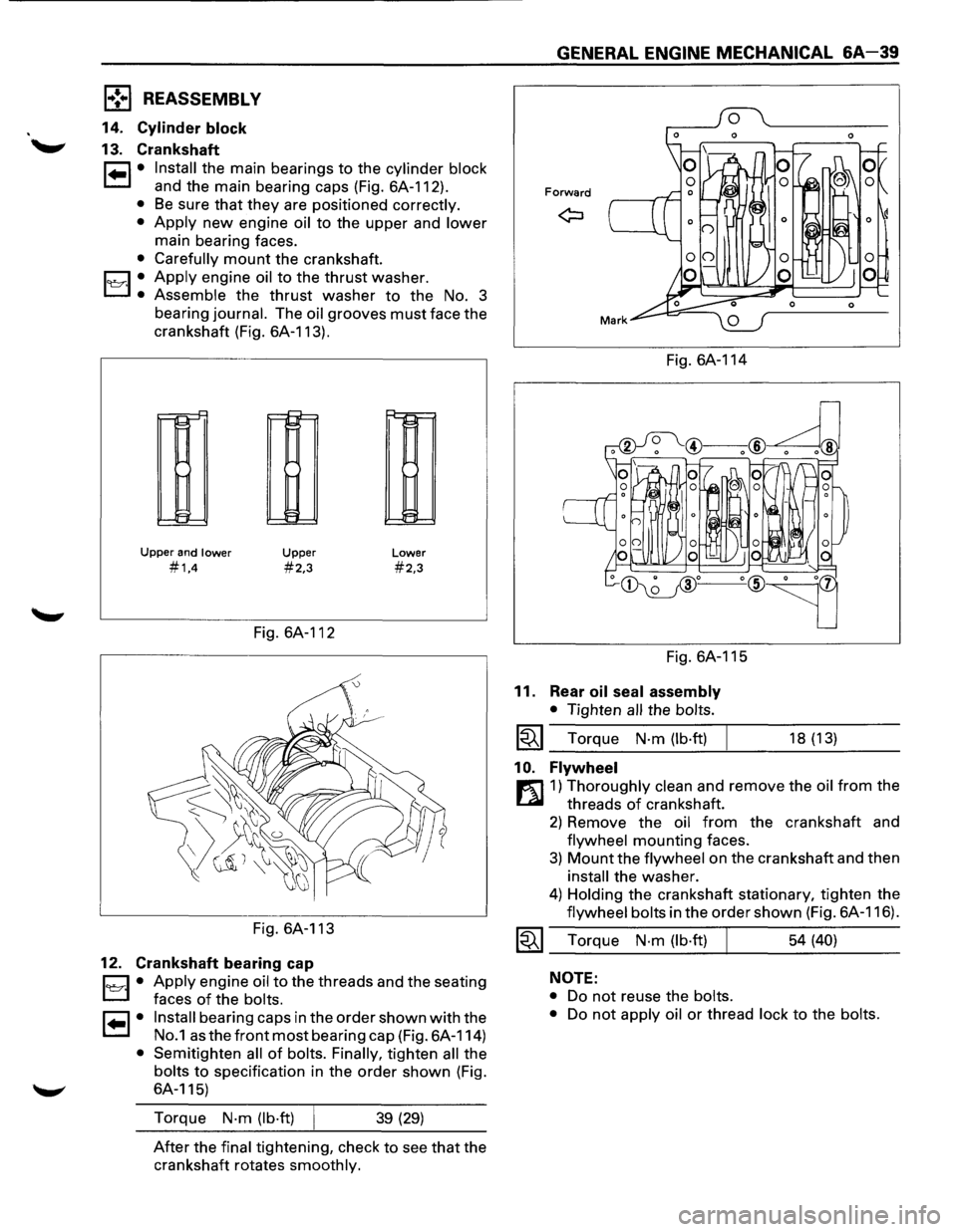
1•1• Install the main bearings to the cylinder block
and the main bearing caps (Fig. 6A-112).
• Be sure that they are positioned correctly.
•
Apply new engine oil to the upper and lower
main bearing faces.
• Carefully mount the crankshaft.
1~·1 .• Apply engine oil to the thrust washer.
Assemble the thrust washer to the No. 3
bearing
journal. The oil grooves must face the
crankshaft (Fig. 6A-113).
r--!::"
11-1
~
Upper and lower
#1,4
Upper
#2,3
Fig. 6A-112
Fig. 6A-113
12. Crankshaft bearing cap
Lower
#2,3
D • Apply engine oil to the threads and the seating
L:J faces of the bolts.
I• I• Install bearing caps in the order shown with the
No.1 as the front most bearing cap (Fig. 6A-114)
• Semitighten all of bolts. Finally, tighten all the
bolts to specification in the order shown (Fig.
6A-115)
Torque
N·m (lb·ft) 39 (29)
After the final tightening, check to see that the
crankshaft rotates
smoothly.
GENERAL ENGINE MECHANICAL &A-39
Forward
Fig. 6A-114
Fig. 6A-115
11. Rear oil seal assembly
• Tighten all the bolts.
~~~ Torque N·m (lb·ft)
1 0. Flywheel
18 (13)
r:l]1) Thoroughly clean and remove the oil from the
threads
of crankshaft.
2) Remove the oil from the crankshaft and
flywheel mounting faces.
3) Mount the flywheel on the crankshaft and then
install the washer.
4) Holding the crankshaft stationary, tighten the
flywheel bolts in the order shown (Fig. 6A-116).
~~~ Torque N·m (lb·ft) 54 (40)
NOTE:
•
Do not reuse the bolts.
•
Do not apply oil or thread lock to the bolts.
Page 609 of 1928
.., ¢'
-
Fig. 6A1-59
1••1 INSTALLATION
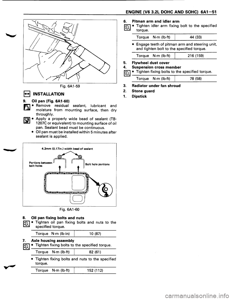
9. Oil pan (Fig. 6A1-60)
m • Remove residual sealant, lubricant and
~ moisture from mounting surface, then dry
throughly.
ISPI• Apply a properly wide bead of sealant (TB-
1207C or equivalent) to mounting surface of oil
pan. Sealant bead must be continuous.
• Oil pan must be installed within 5 minutes after
sealant is applied.
4.3mm (0.17in.) width bead of sealant
Portions between bolt holes
Fig. 6A1-60
8. Oil pan fixing bolts and nuts
Bolt hole portions
~ • Tighten oil pan fixing bolts and nuts to the
~ specified torque.
Torque
N·m (lb·in)
10 (87)
7. Axle housing assembly
~~~· Tighten fixing bolts to the specified torque.
Torque
N·m (lb·ft) 82 (61)
• Tighten fixing bolts and nuts to the specified
torque.
Torque
N·m (lb·ft) 152 (112)
ENGINE (V6 3.2L DOHC AND SOHC) 6A 1-51
6. Pitman arm and idler arm
~·
Tighten idler arm fixing bolt to the specified
torque.
Torque
N·m (lb·ft) 44 (33)
• Engage teeth of pitman arm and steering unit,
and tighten
bolt to the specified torque.
Torque
N·m (lb·ft) 216 (159)
5. Flywheel dust cover
4. Suspension cross member
~~~ • Tighten fixing bolts to the specified torque.
Torque
N·m (lb·ft) I 78 (58)
3. Radiator under fan shroud
2. Stone guard
1. Dipstick
Page 616 of 1928
,): .. • T·
6A 1-58 ENGINE (V6 3.2L DOHC AND SOHC)
EJ REMOVAL
1. Engine assembly
• See "Engine Assembly
Removal and Instal-
lation".
2. Crankshaft pulley
3. Timing belt cover
4. Timing belt
5. Oil pan
6. Oil pipe and rubber ring
7. Oil strainer and rubber ring
8. Oil pump assembly
9. Crankcase side bolts
10.
Oil gallery
11. Flywheel
12.
Rear oil seal retainers
13.
Connecting rod caps
14.
Crankshaft main bearing caps
15.
Crankshaft and main bearings
1•+1 INSTALLATION
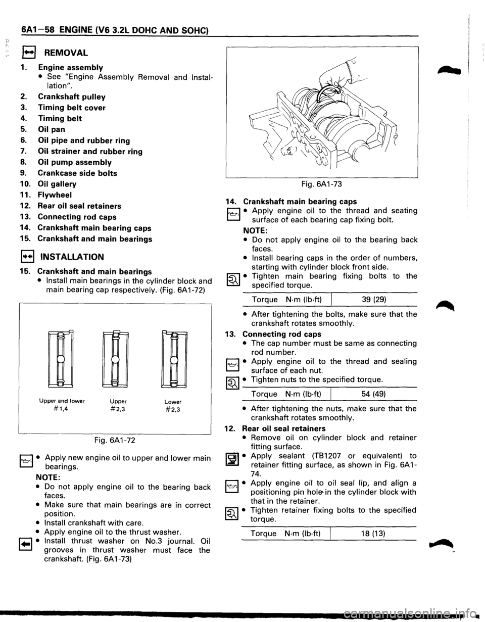
15. Crankshaft and main bearings
• Install main bearings in the cylinder block and
main bearing cap respectively. (Fig. 6A1-72)
r-r-'
II-
!:=
Upper and lower
#1,4
~
!::
E:
Upper
#2,3
Fig. 6A1-72
Lower
#2,3
1~1· Apply new engine oil to upper and lower main
bearings.
NOTE:
• Do not apply engine oil to the bearing back
faces.
• Make sure that main bearings are in correct
position.
• Install crankshaft with care.
• Apply engine oil to the thrust washer.
1•1• Install thrust washer on No.3 journal. Oil
grooves in thrust washer must face the
crankshaft. (Fig. 6A1-73) Fig.
6A1-73
14. Crankshaft main bearing caps
C1 • Apply engine oil to the thread and seating
L:::J surface of each bearing cap fixing bolt.
NOTE:
• Do not apply engine oil to the bearing back
faces.
• Install bearing caps in the order of numbers,
starting
with cylinder block front side.
~~~ • Tighten main bearing fixing bolts to the
specified torque.
Torque
N·m (lb·ft) I 39 (29)
• After tightening the bolts, make sure that the
crankshaft rotates
smoothly.
13. Connecting rod caps
• The cap number must be same as connecting
rod number.
1~1· Apply engine oil to the thread and sealing
surface of each nut.
~~~· Tighten nuts to the specified torque.
Torque
N·m (lb·ft) 54 (49)
• After tightening the nuts, make sure that the
crankshaft rotates
smoothly.
12. Rear oil seal retainers
• Remove oil on cylinder block and retainer
fitting surface.
~~~· Apply sealant (TB1207 or equivalent) to
retainer fitting surface, as shown in Fig. 6A 1-
74.
C1 • Apply engine oil to oil seal lip, and align a
El positioning pin hole< in the cylinder block with
that in the retainer.
~~~· Tighten retainer fixing bolts to the specified
torque.
Torque
N·m (lb·ft) 18 (13)
IIIII
Page 617 of 1928
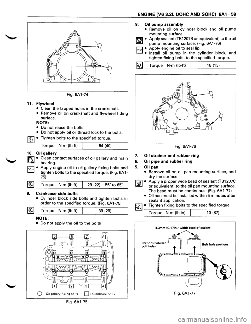
Fig. 6A1-74
11. Flywheel
• Clean the tapped holes in the crankshaft.
• Remove oil on crankshaft and flywheel fitting
surface.
NOTE:
• Do not reuse the bolts.
•
Do not apply oil or thread lock to the bolts.
~~~ • Tighten bolts to the specified torque.
Torque
N-m (lb·ft) 54 (40)
10. Oil gallery
m • Clean contact surfaces of oil gallery and main
~ bearing.
D • Apply engine oil to oil gallery fixing bolts and
L:::J tighten bolts to the specified torque. (Fig. 6A 1-
75)
~~~ Torque N·m (lb·ft) 29 (22) -55° to 65°
9. Crankcase side bolts
• Cylinder block side bolts and tighten bolts in
order
to the specified torque. (Fig. 6A 1-75)
~~~ Torque N·m (lb·ft) 39 (29)
NOTE:
• Do not apply the oil to the bolts
0 :Oil gallery fixing bolts 0: Crankcase bolts
Fig. 6A1-75
ENGINE (V6 3.2L DOHC AND SOHC) 6A1-59
8. Oil pump assembly
• Remove oil on cylinder block and oil pump
mounting surface.
ll:JI• Apply sealant (TB12078 or equivalent) to the oil
pump mounting surface. (Fig. 6A1-76)
19Y·I •. Apply engine oil to seal lip.
Install oil
pump in the cylinder block, and
tighten fixing
bolts to the specified torque.
1~1 Torque N·m (lb·ft)
Fig. 6A1-76
7. Oil strainer and rubber ring
6. Oil pipe and rubber ring
5. Oil pan
18 (13)
• Remove oil on oil pan mounting surface, and
dry the surface.
~~~· Apply a proper wide bead of sealant (TB1207C
or equivalent) to the oil pan mounting surface.
The bead
must be continuous. (Fig. 6A1-77)
• Oil pan must be installed within 5 minutes after
sealant application.
~~~· Tighten fixing bolts to the specified torque.
Torque
N·m (lb·in) 10 (87)
4.3mm (0.17in.) width bead of sealant
Portions between bolt holes I Bolt hole portions
D
Fig. 6A1-77