wheel torque ISUZU TROOPER 1995 Manual PDF
[x] Cancel search | Manufacturer: ISUZU, Model Year: 1995, Model line: TROOPER, Model: ISUZU TROOPER 1995Pages: 1928
Page 1056 of 1928
7A-184 AUTOMATIC TRANSMISSION (4L30-E)
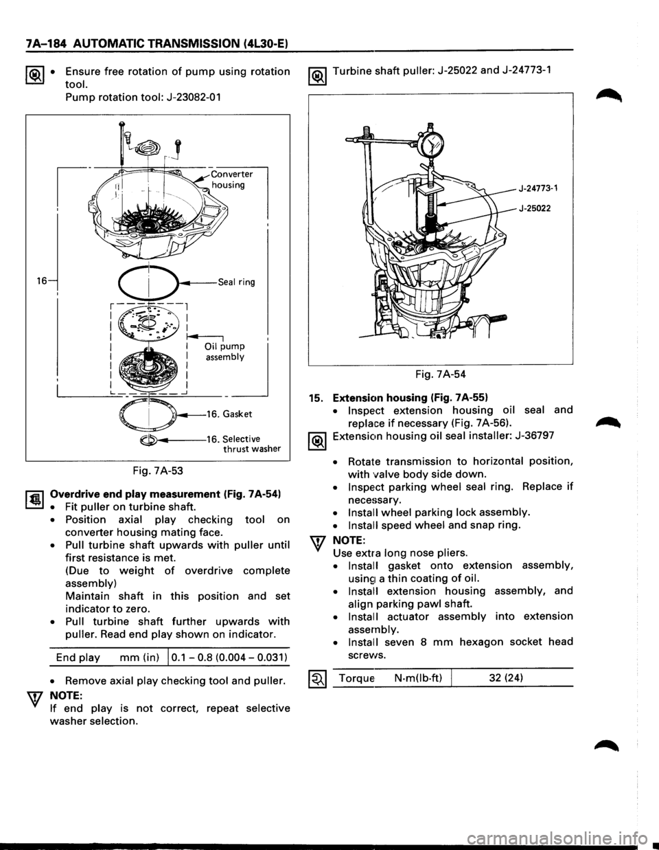
~· Ensure free rotation of pump using rotation
tool.
16
Pump rotation tool: J-23082-01
-----16. Selective thrust washer
Fig. 7A-53
l'fil Overdrive end play measurement (Fig. 7A-54)
~ • Fit puller on turbine shaft.
• Position axial play checking tool on
converter housing mating face.
• Pull turbine shaft upwards with puller until
first resistance is met.
(Due
to weight of overdrive complete
assembly)
Maintain shaft in this position and set
indicator to zero.
• Pull turbine shaft further upwards with
puller. Read end play shown on indicator.
End
play mm (in) I 0.1 -0.8 (0.004-0.031)
1®.1 Turbine shaft puller: J-25022 and J-24773-1
J-24773·1
J-25022
Fig. 7A-54
15. Extension housing (Fig. 7A-55)
• Inspect extension housing oil seal and
replace if necessary (Fig. 7 A-56).
1®.1 Extension housing oil seal installer: J-36797
• Rotate transmission to horizontal position,
with valve body side down.
• Inspect parking wheel seal ring. Replace if
necessary.
• Install wheel parking lock assembly.
• Install
speed wheel and snap ring.
NOTE:
Use extra long nose pliers.
• Install
gasket onto extension assembly,
usin£1 a thin coating of oil.
• Install
extension housing assembly, and
align parking pawl shaft.
• Install actuator assembly into extension
assembly.
• Install
seven 8 mm hexagon socket head
screws.
• Remove axial play checking tool and puller. ~~~ Torque N-m(lb.ft) 32 (24) W NOTE: _ __:_ ___ __:___:__J_ _ __.::..:::....=_:..:.__ __
If end play is not correct, repeat selective
washer selection.
Page 1057 of 1928
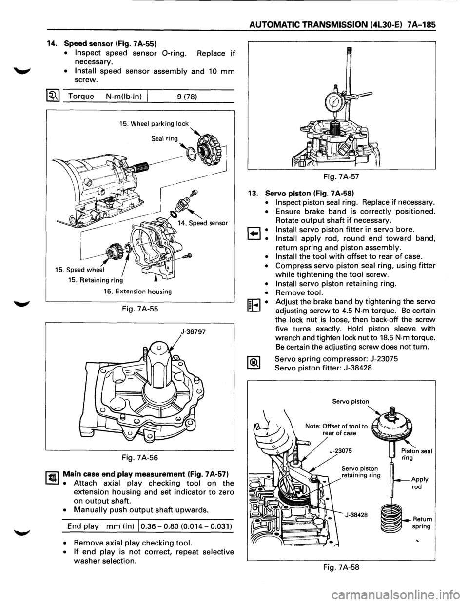
14. Speed sensor (Fig. 7A-55)
• Inspect speed sensor 0-ring. Replace if
necessary.
~ • Install speed sensor assembly and 10 mm
screw.
~~~ Torque N-m(lb-in) 9 (78)
15. Wheel parking lock
15. Retaining ring
15. Extension housing
Fig. 7A-55
J-36797
Fig. 7A-56
rfil Main case end play measurement (Fig. 7A-57)
~ • Attach axial play checking tool on the
extension housing and set indicator to zero
on
output shaft.
• Manually push output shaft upwards.
End play mm (in) 10.36-0.80 (0.014-0.031)
• Remove axial play checking tool.
• If end play is not correct, repeat selective
washer selection.
AUTOMATIC TRANSMISSION (4l30-E) 7A-185
Fig. 7A-57
13. Servo piston (Fig. 7A-58)
•
•
8:
•
•
•
•
[E•
Inspect piston seal ring. Replace if necessary .
Ensure brake band is correctly
positioned .
Rotate
output shaft if necessary.
Install servo piston fitter in servo bore.
Install apply rod, round end toward band,
return
spring and piston assembly.
Install the tool with offset to rear of case .
Compress servo
piston seal ring, using fitter
while tightening the tool screw.
Install servo piston retaining ring .
Remove
tool.
Adjust the brake band by tightening the servo
adjusting screw
to 4.5 N-m torque. Be certain
the lock nut
is loose, then back-off the screw
five turns exactly. Hold piston sleeve with
wrench and tighten lock nut to
18.5 N-m torque.
Be certain the adjusting screw does not turn.
Servo
spring compressor: J-23075
Servo piston fitter: J-38428
Servo piston
Note: Offset
of tool to rear of case
Servo piston
retaining ring
J-38428
Fig. 7A-58
~~--Return spring
Page 1099 of 1928
12. Flywheel under cover bolts
• Install
three flywheel under cover bolts.
11. Gear control lever
• Install
the transmission control lever and
transfer
control lever.
• Install
the grommet assembly.
• Install
the front console assembly.
• Install
the gear control lever knob.
• Support the transfer case with a jack and then
remove the transmission jack
from
transmission side.
10. Front propeller shaft
• Install the front propeller shaft.
~~~ Torque N·m (lb·ft) 63 (46)
9. Front crossmember
• Install the front crossmember.
~~~ Torque N·m (lb·ft) 78 (58)
8. Engine rear mount
• Install the engine rear mount.
~~~ Torque N·m (lb·ft) 41 (30)
7. 3rd crossmember
• Install the 3rd crossmember.
1~1 Torque N-m (lb·ft) 50 (37)
6. Engine rear mount nuts
~~~ Torque N-m (lb·ft) 50 (37)
• Remove the transmission jack.
5. Transmission harness connectors
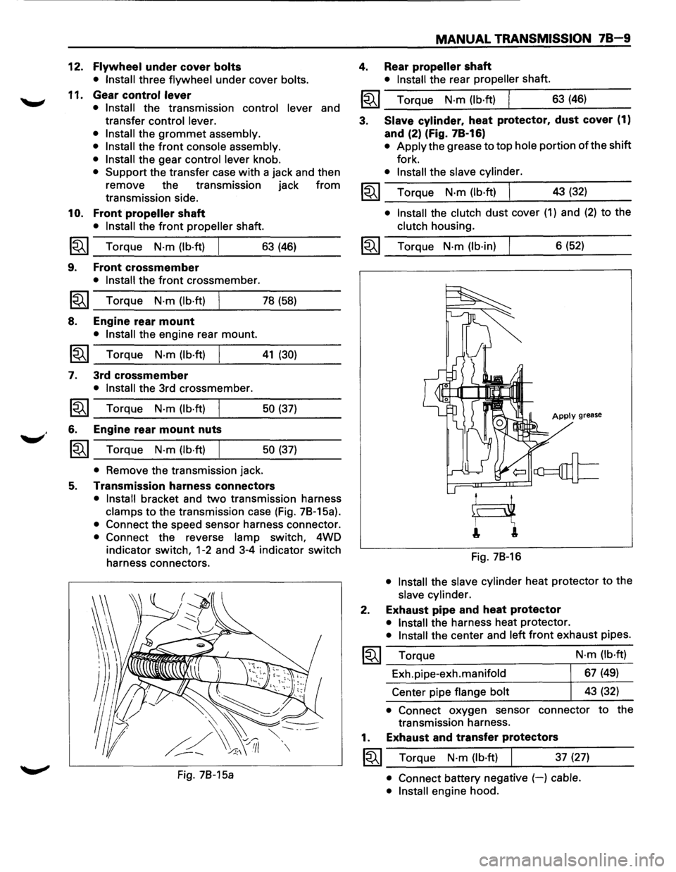
• Install bracket and two transmission harness
clamps to the transmission case (Fig. 78-15a).
• Connect the speed sensor harness connector.
• Connect the reverse lamp switch, 4WD
indicator
switch, 1-2 and 3-4 indicator switch
harness connectors.
Fig. 78-15a
MANUAL TRANSMISSION 78-9
4. Rear propeller shaft
• Install the rear propeller shaft.
I~I __ T_o_rq~u_e __ N_·m~(_lb_·ft~)~ _____ 6_3~(_46~) ____ _
3. Slave cylinder. heat protector. dust cover (1)
and (2) (Fig. 78-16)
• Apply the grease to top hole portion of the shift
fork.
• Install the slave cylinder.
~~~ Torque N·m (lb·ft) I 43 (32) _..:....__~----
• Install the clutch dust cover (1) and (2) to the
clutch housing.
~~~ Torque N·m (lb·in) 6 (52)
Apply grease
Fig. 78-16
• Install the slave cylinder heat protector to the
slave cylinder.
2. Exhaust pipe and heat protector
• Install the harness heat protector.
• Install the center and left front exhaust pipes.
~~~ Torque
Exh.pipe-exh.manifold
Center pipe
flange bolt N·m
(lb·ft)
67 (49)
43 (32)
• Connect oxygen sensor connector to the
transmission harness.
1. Exhaust and transfer protectors
~~~ Torque N·m (lb·ft) 37 (27)
• Connect battery negative (-) cable.
• Install
engine hood.
Page 1145 of 1928
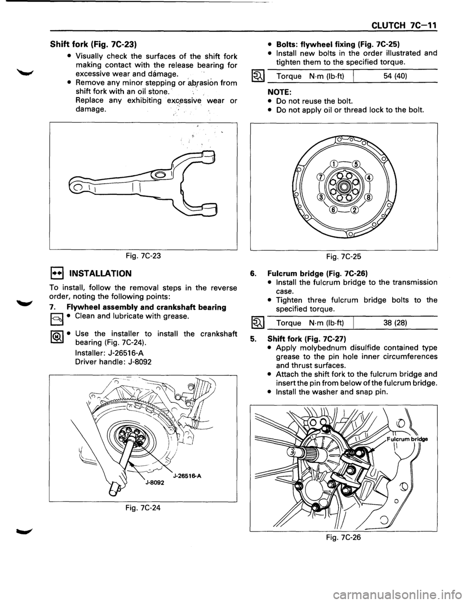
Shift fork (Fig. 7C-23)
• Visually check the surfaces of the shift fork
making contact
with the release bearing for
excessive wear and damage.
• Remove any minor stepping or ah,rasion from
shift fork with an oil stone.
Replace any exhibiting
· ex«?~ssive wear or
damage.
Fig.
7C-23
1••1 INSTALLATION
To install, follow the removal steps in the reverse
order, noting the
following points:
7. Flywheel assembly and crankshaft bearing
§I• Clean and lubricate with grease.
1®..1• Use the installer to install the crankshaft
bearing (Fig. 7C-24).
Installer: J-26516-A
Driver handle: J-8092
Fig.
7C-24
CLUTCH 7C-11
• Bolts: flywheel fixing (Fig. 7C-25)
• Install new bolts in the order illustrated and
tighten them to the specified torque.
1~1 Torque N·m (lb·ft) I 54 (40)
6.
NOTE:
• Do not reuse the bolt.
•
Do not apply oil or thread lock to the bolt.
Fig. 7C-25
Fulcrum bridge (Fig. 7C-26)
• Install the fulcrum bridge to the transmission
case.
• Tighten three fulcrum bridge bolts to the
specified torque.
I~I __ T_o_rq~u_e __ N_·_m~(_lb_·ft_l~ _____ 3_8_(_28_) ____ _
5. Shift fork (Fig. 7C-27)
• Apply molybednum disulfide contained type
grease
to the pin hole inner circumferences
and thrust surfaces.
• Attach the shift fork to the fulcrum bridge and
insert the pin
from below of the fulcrum bridge.
• Install the washer and snap pin.
Fig.
7C-26
Page 1149 of 1928
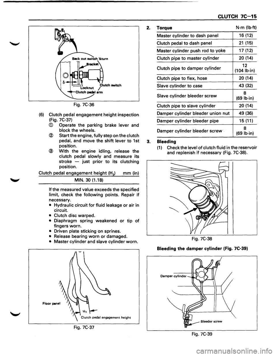
Fig. 7C-36
(6) Clutch pedal engagement height inspection
(Fig.
7C-37)
® Start the engine, fully step on the clutch
pedal,
and move the shift lever to 1st
position.
@ With the engine idling, release the
clutch pedal slowly and measure its
stroke -just prior
to its clutching
position.
Clutch pedal engagement height (H3) mm (in)
MIN. 30 (1.18)
If the
measured value exceeds the specified
limit, check the following points. Repair if
necessary.
• Hydraulic circuit for fluid leakage or air in
circuit.
• Clutch disc warped.
• Diaphragm spring weakened or tip of
fingers worn.
• Driven plate sticking on sprines.
• Release bearing worn or damaged.
• Master cylinder and slave cylinder worn.
Floor panel
Fig. 7C-37
CLUTCH 7C-15
2. Torque N·m (lb·ft)
Master cylinder to dash panel 16 (12)
Clutch pedal to dash panel 21 (15)
Master cylinder push rod to yoke 17 (12)
Clutch pipe to master cylinder 20 (14)
Clutch pipe
to damper cylinder 12
(104 lb·in)
Clutch
pipe to flex, hose 20 (14)
Slave cylinder to case 43 (32)
Slave
cylinder bleeder screw 8 (691b·in)
Clutch
pipe to slave cylinder 20 (14)
Damper cylinder bleeder union nut 49 (36)
Damper cylinder bleeder pipe 15 (11)
Damper cylinder
bleeder screw 8 (69 lb·in)
3. Bleeding
(1) Check
the level of clutch fluid in the reservoir
and
replenish if necessary (Fig. 7C-38).
Fig. 7C-38
Bleeding the damper cylinder (Fig. 7C-39)
Damper cylinder
Fig. 7C-39
Page 1159 of 1928
TRANSFER CASE 7D-1
SECTION 70
TRANSFER CASE
w CAUTION:
When fasteners are removed, always reinstall them at the same location from which they were removed. If a
fastener needs
to be replaced, use the correct part number fastener for that application. If the correct part
number is not available, a fastener
of equal size and strength (or stronger) may be used. Fasteners that are
not reused, and those requiring thread locking compound, will
be called out. The correct torque values must
be used when installing fasteners that require torque.
If the above conditions are not followed, parts or
system damage could result.
CONTENTS
General Description ................... 7D-1
Construction . . . . . . . . . . . . . . . . . . . . . . . . . 7D-2
On-Vehicle Service .................... 7D-3
Transfer
Case (A/T) .................. 7D-3
Transfer Rear
Oil Seal ................ 7D-5
Unit Repair ........................... 7D-8
Transfer
Case Assembly (AfT) ........ 7D-8
Transfer Rear
Case Assembly . .
. . . . . 7D-11
Detent, Shift Arm, And
Interlock Pin (Transfer
Case Assembly) . .
. . . . . . . . . . . . . . . . . . 7D-14 Transfer
Case
Assembly . .
. . . . . . . . . .
7D-17
Main Data And Specifications . . . . . . . .
70-29
General
Specifications . .
. . . . . . . . . . . .
70-29
Torque
Specifications ............... 7D-30
Special Tools
........................ 7D-32
GENERAL DESCRIPTION
The transfer case is used to provide a means of
providing power flow to the front axle. The transfer
case also provides a means of disconnecting the front
axle, providing better fuel economy and quieter
operation when the vehicle is driven
on improved
roads where four wheel drive is not required.
In
addition, the transfer case provides an additional gear
reduction when placed in low range, which
is useful
when difficult off-road conditions are encountered. A
floor mounted shift lever is used to select the
operating range. When four wheel drive has been
selected, the four wheel drive indicator light is
designed to come
on when the front axle has been
engaged.
Page 1191 of 1928

CHASSIS ELECTRICAL 8-1
·SECTION 8
CHASSIS ELECTRICAL
'\f CAUTION: .
When fasteners are removed, always reinstall them at the same location from which they were removed.
If a fastener needs to be replaced, use the correct part number fastener for that application. If the correct
part number fastener is not
available, a fastener of equal size and strength (or stronger) may be used.
Fasteners that are not reused, and those requiring thread
locking compound, will be called out. The correct
torque
values must be used when installing fasteners that require it. If the above conditions are not
followed, parts or system damage could result.
CONTENTS
General Information .................................... 8-2
Notes for Working on Electrical
Items .................................................... 8-2
Symbols and Abbreviations ................. 8-8
Symbols ............................................ 8-8
Abbreviations ................................... 8-9
Parts for Electrical Circuit ..................... 8-10
Wiring ............................................... 8-10
Fuse .................................................. 8-11
Fusible Link ....................................... 8-12
Circuit Breaker ................................... 8-12
Relay ................................................. 8-12
Relay Specifications and
Configurations ................................ 8-13
Diode ................................................. 8-14
Connector ......................................... 8-15
Reading the Circuit Diagram ................ 8-17
Main Data and Specifications .................... 8-19
Bulb Specifications ................................ 8-19
Fuse,
Fusible Link and
Circuit Breaker Location ..................... 8-21
Fuse
Block Circuit .................................. 8-22
Reference Table of Fuse, Fusible
Link and Circuit Breaker ..................... 8-23
Relay Location ....................................... 8-27
Diode Location .......................................
8-28
Grounding Point .................................... 8-29
Reference Table ................................ 8-29
Location ............................................ 8-31
Cable Harness Routing .......................... 8-34
System Repair .............................................. 8-38
Start and Charging ................................ 8-38
Engine Control Module
(ECM) ................................................... 8-47
Headlight and Fog Light ........................ 8-58
Front Side Marker Light, Parking Light,
Taillight, License Plate Light and
Illumination Light .............................. 8-76
Stoplight and Rear Defogger .............. 8-92
Turn Signal Light, Hazard
Warning
Light, Cornering Light,
Backup
Light and Horn ..................... 8-106
Dome Light, Luggage room Light,
Courtesy Light, Map Light,
Seat Belt Switch and
Warning Buzzer ................................. 8-128
Power Door Lock ................................. 8-142
Power
Window .................................... 8-156
Cruise
Control ...................................... 8-172
Anti-Lock Brake
System (ABS) ........... 8-178
Rear
Wheel Anti-Lock Brake
System (RWAL) ................................. 8-185
Transmission
Control Module
(TCM) ................................................. 8-192
A/T Shift Lock ...................................... 8-200
Windshield
Wiper/Washer and
Rear
Wiper/Washer .......................... 8-205
Headlight wiper /washer ..................... 8-232
Audio, Auto Antenna,
Cigarette
Lighter and digital clock ... 8-246
Power Door Mirror ............................... 8-254
Anti-theft System ................................ 8-270
Meter and Warning/Indicator Light ... 8-288
A/T Shift Indicator ............................... 8-336
Heater and
Air Conditioning ............... 8-340
Sun
Roof ............................................... 8-346
Power Seat ........................................... 8-360
Seat
Heater .......................................... 8-37 4
Supplemental Restraint
System (SRS) -AIR BAG ................... 8-382
Page 1260 of 1928
I ..
8 -70 CHASSIS ELECTRICAL
When placing a live inflator module on a bench
or other surface, always face the bag and trim
cover up, away from the surface. This is neces
sary so that a free space is provided to allow the
air bag to expand in the unlikely event of acci·
dental
deployment.
4. Steering wheel
• Refer to STEERING WHEEL REPLACEMENT in
Section 3F4.
5. Lighting switch (Combination switch)
• Disconnect the switch connector.
• Remove four screws.
• Remove the lighting switch together with SRS
coil assembly.
'\f CAUTION:
Do not remove SRS coil assembly from the com·
bination switch assembly.
E) INSTALLATION
To install, follow the removal steps in the reverse
order, noting the
following points.
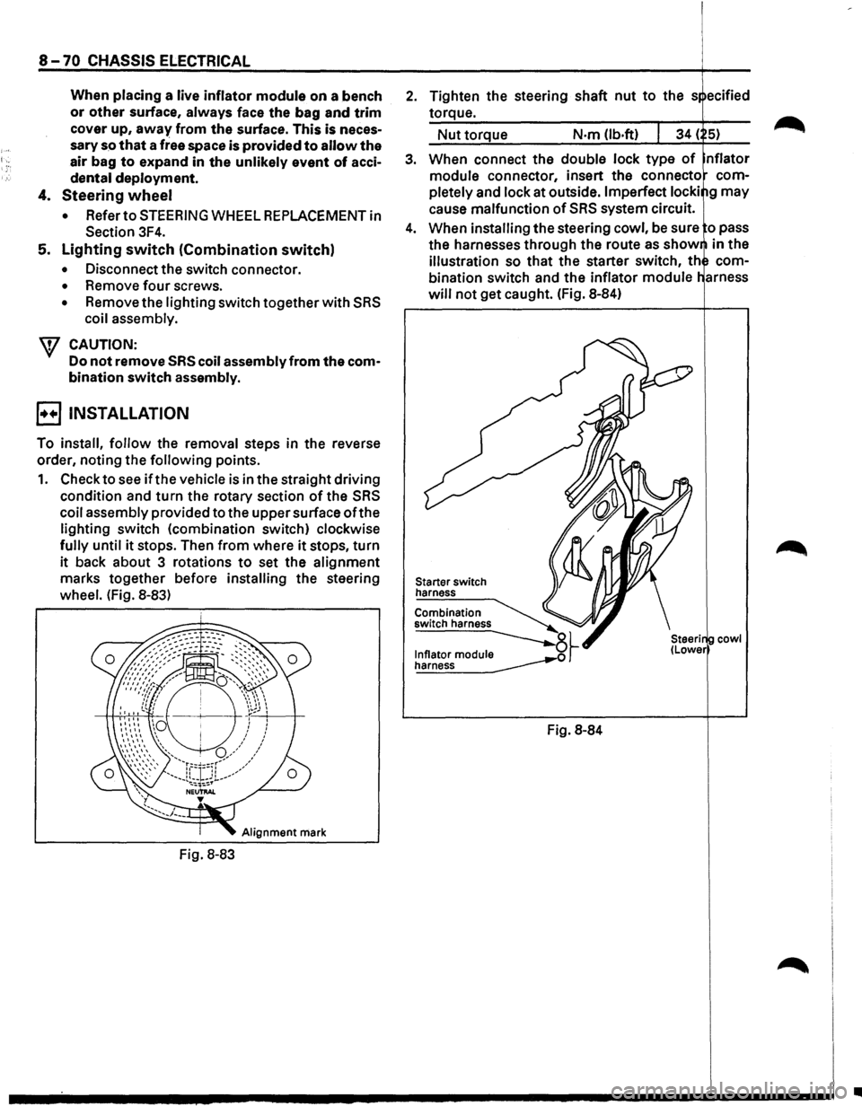
1. Check to see if the vehicle is in the straight driving
condition and turn the rotary section of the SRS
coil assembly provided to the upper surface ofthe
lighting switch (combination switch) clockwise
fully until it stops. Then from where it stops, turn
it back about 3 rotations to set the alignment
marks together before installing the steering
wheel. (Fig. 8-83)
Alignment mark
Fig. 8-83
2. Tighten the steering shaft nut to the s ecified
torque.
Nut torque N·m (lb.ft)
3. When connect the double lock type of nflator
module connector, insert the connecto com
pletely
and lock at outside. Imperfect locki g may
cause malfunction of SRS system circuit.
4. When installing the steering cowl, be sure o pass
the harnesses
through the route as show in the
illustration so that the starter switch, th com
bination switch and the inflator module
will not get caught. (Fig. 8-84)
Starter switch
harness
Combination
switch harness
~~ ~
Fig. 8-84
cowl
•
Page 1739 of 1928
Supplemental iraint System
TABLE OF CONTENTS
SUPPLEMENTAL RESTRAINT SYSTEM
{SRS)
SECTION 3 -SERVICE
9J-115
CAUTION: WHEN FASTENERS ARE REMOVED, ALWAYS REINSTALL THEM AT THE SAME LOCATION
FROM WHICH
THEY WERE REMOVED. IF A FASTENER NEEDS TO BE REPLACED, USE THE CORRECT PART
NUMBER FASTENER
FOR THAT APPLICATION. IF THE CORRECT PART NUMBER FASTENER IS NOT
AVAILABLE,
A FASTENER OF EQUAL SIZE AND STRENGTH (OR STRONGER) MAY BE USED. FASTENERS
THAT ARE NOT REUSED, AND THOSE REQUIRING THREAD LOCKING COMPOUND WILL BE CALLED OUT.
THE CORRECT TORQUE VALUE MUST BE USED WHEN INSTALLING FASTENERS THAT REQUIRE IT. IF THE
ABOVE CONDITIONS ARE NOT FOLLOWED, PARTS OR SYSTEM DAMAGE COULD RESULT.
SERVICE PRECAUTIONS . . . . . . . . . • . . . . . • • . . . . . . . . • . • • . . . . . . . . . . . • . . • • . . . . . . . 117
Disabling the SRS . . . . . . . . . . . . . . . . . . . . . . . . . . . . . . . . . . . . . . . . . . . . . . . . . . . . . . . . . . . 117
Enabling the SRS • • • • • • • • • • • • • • • • • • • • • • • • • • • • • • • • • • • • • • • • • • • • • • • • • • • • • • • • • • • 117
Handling/Installation/Diagnosis • • • • • • • • • • • • • • • • • • • • • • • • • • • • • • • • • • • • • • • • • • • • • • • • 117
Inspections Required After Accident • • • • • • • • • • • • • • • • • • • • • • • • • • • • • • • • • • • • • • • • • • • • 117
DIAGNOSTIC ENERGY RESERVE MODULE (DERM) • • . • • . • • • • . . • . . . • • . . . . • . . . • 119
DISCRIMINATING SENSOR-FORWARD SENSOR LH . • . . • • . • . . • . . • . • . . . • • . . • • . 120
DISCRIMINATING SENSOR
-FORWARD SENSOR RH • . • . . . • • • . • . . . . • • . • . . . . . • • 121
DUAL POLE ARMING SENSOR . . . . . . . . . . • . . . . . • . . . . . . . . . . . . • • . . . . . . . . • . . . . . . . 122
DRIVER INFLATOR MODULE ............•..•........•....•....•....•.........
STEERING WHEEL •........•........•.•......••........•..••..•\
•....•....•..
SRS COIL ASSEMBLY ....•......•.•......•.............•••..•....•\
.....•..••
124
125
127
STEERING COLUMN . . . . . . . . . . . . . . . . . . . . . . . . . . . . . . . . . . . . . . . . . . . . . . . . . . . . . . . . 129
PASSENGER INFLATOR MODULE . . . • . . . . . • . • • . . . . . . . . • . . . • • . . • • . . • • . . . . • • . . • 132
SPECIFICATION . .
. . . . . . . . . . . . . .
• . .
. . . . . .
• . .
. . . .
• • • • • • . . • • . • • • . .
.
• . .
. .
• • . .
.
• • 133
Page 1748 of 1928
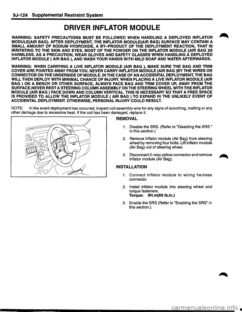
9J·124 Supplemental Restraint System
DRIVER INFLATOR MODULE
WARNING: SAFETY PRECAUTIONS MUST BE FOLLOWED WHEN HANDLING A DEPLOYED INFLATOR
MODULE(AIR
BAG). AFTER DEPLOYMENT, THE INFLATOR MODULE(AIR BAG} SURFACE MAY CONTAIN A
SMALL AMOUNT OF SODIUM HYDROXIDE, A BY-PRODUCT OF THE DEPLOYMENT REACTION, THAT IS
IRRITATING TO
THE SKIN AND EYES. MOST OF THE POWDER ON THE INFLATOR MODULE (AIR BAG )IS
HARMLESS.
AS A PRECAUTION, WEAR GLOVES AND SAFETY GLASSES WHEN HANDLING A DEPLOYED
INFLATOR MODULE (AIR BAG ), AND WASH YOUR HANDS WITH MILD SOAP AND WATER AFTERWARDS.
WARNING:
WHEN CARRYING A LIVE INFLATOR MODULE (AIR BAG }, MAKE SURE THE BAG AND TRIM
COVER
ARE POINTED AWAY FROM YOU. NEVER CARRY INFLATOR MODULE (AIR BAG )BY THE WIRES OR
CONNECTOR
ON THE UNDERSIDE OF MODULE. IN THE CASE OF AN ACCIDENTAL DEPLOYMENT, THE BAG
WILL THEN DEPLOY WITH MINIMAL CHANCE OF INJURY. WHEN PLACING A LIVE INFLATOR MODULE (AIR
BAG ) ON A BENCH OR OTHER SURFACE, ALWAYS FACE BAG AND TRIM COVER UP, AWAY FROM THE
SURFACE.NEVER REST A STEERING COLUMN ASSEMBLY ON THE STEERING WHEEL WITH THE INFLATOR
MODULE (AIR BAG } FACE DOWN AND COLUMN VERTICAL. THIS IS NECESSARY SO THAT A FREE SPACE
IS PROVIDED TO
ALLOW THE INFLATOR MODULE (AIR BAG} TO EXPAND IN THE UNLIKELY EVENT OF
ACCIDENTAL DEPLOYMENT. OTHERWISE, PERSONAL INJURY COULD RESULT.
NOTE:
In the event deployment has occurred, inspect coil assembly wire for any signs of scorching, melting or any
other damage due to excessive heat.
If the coil has been damaged, replace it.
REMOVAL
1. Disable the SRS. (Refer to "Disabling the SRS "
in this section.)
2. Remove inflator module (Air Bag) from steering
wheel by removing four bolts. Lift inflator module
(Air Bag) out of steering wheel.
3. Disconnect 2-way yellow connector and remove ~
inflator module (Air Bag).
INSTALLATION
1. Connect inflator module to wiring harness
connector.
2. Install inflator module into steering wheel and
torque fasteners.
Torque: 8N.m(69 lb.ln.)
3. Enable the SRS (Refer to "Enabling the SRS" in
this section.).
•