roof ISUZU TROOPER 1995 Owner's Manual
[x] Cancel search | Manufacturer: ISUZU, Model Year: 1995, Model line: TROOPER, Model: ISUZU TROOPER 1995Pages: 1928
Page 1759 of 1928
BODY 10-1
SECTION 10
BODY
\V CAUTION : When fasteners are removed, always reinstall them at the same location from which they
were removed. If a fastener needs to be replaced, use the correct part number fastener for
that application. If the correct part number fastener is not available, a fastener of equal size
and strength (or stronger)
may be used. Fasteners must be used when installing fasteners
that require it. If the above conditions are not followed, parts of system damage could result.
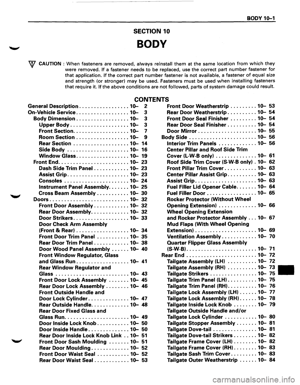
CONTENTS
General Description ................. 10-2 Front Door Weatherstrip ......... 10-53
On-Vehicle Service .................. 10-3 Rear Door Weatherstrip .......... 10-54
Body Dimension .................. 10-3 Front Door Seal Finisher ......... 10-54
Upper Body .................... 10-3 Rear Door Seal Finisher .......... 10-54
Front Section ................... 10-7 Door Mirror .................... 10-55
Room Section .................. 10-9 Body Side ....................... 10-56
Rear Section ................... 10-14 Interior Trim Panels ............. 10-56
Side Body ..................... 10-16 Center Pillar and Roof Side Trim
Window Glass .................. 10-19 Cover (L·W·B only) .............. 10-61
Front End ........................ 10-23 Roof Side Trim Cover (S·W·B only) . 10-62
Dash Side Trim Panel ............ 10-23 Front Pillar Trim Cover ........... 10-63
Assist Grip ..................... 10-23 Center Pillar Assist Grip .......... 10-63
Consoles ...................... 10-24 Assist Grip ..................... 10-63
Instrument Panel Assembly ....... 10-25 Fuel Filler lid Opener Cable ....... 10-64
Cross Beam Assembly ........... 10-30 Fuel Filler Door ................. 10-65
Doors ........................... 10-32 Rocker Protector (Without Wheel
Front Door Assembly ............ 10-32 Opening Extension) ............. 10-66
Rear Door Assembly ............. 10-32 Wheel Opening Extension
Door Strikers ................... 10-33 and Rocker Protector Assembly ... 10-67
Door Check Arm Assembly Mud Flaps (With Wheel Opening
(Front & Rear) .................. 10-34 Extension) ..................... 10-69
Front Door Trim Panel ........... 10-35 Ventilation Assembly ............ 10-70
Rear Door Trim Panel ............ 10-38 Quarter Flipper Glass Assembly
Door Wood Panel Assembly ...... 10-40 (S·W·B) ........................ 10-71
Front Window Regulator, Glass Rear End ........................ 10-72
and Glass Run .................. 10-41 Tailgate Assembly (LH) .......... 10-72
Rear Window Regulator and Tailgate Assembly (RH) .......... 10-73
Glass ......................... 10-43 Tailgate Strikers ................ 10-75
Front Door Lock Assembly ....... 10-45 Tailgate Trim Panel (LH) .......... 10-75
Rear Door Lock Assembly ........ 10-46 Tailgate Trim Panel (RH) .......... 10-76
Front Outside Handle and Tailgate Lock Assembly (LH) ...... 10-77
Door Lock Cylinder .............. 10-47 Tailgate Lock Assembly (RH) ...... 10-78
Rear Outside Handle ............. 10-48 Tailgate Inside Lock Knob ........ 10-79
Rear Door Fixed Glass and Tailgate Outside Handle and/or
Glass Run ...................... 10-49 Tailgate Lock Cylinder ........... 10-80
Door Inside Lock Knob ........... 10-50 Tailgate Stopper Assembly ....... 10-81
Door Inside Handle .............. 10-50 Tailgate Dove-tail ............... 10-81
Rear Door Inside Lock Knob Link .. 10-51 Tailgate Dove-tail Strikers ........ 10-82
Front Door Sash Moulding ....... 10-51 Tailgate Frame Cover (LH) ........ 10-82
Rear Door Moulding ............. 10-52 Tailgate Frame Cover (RH) ........ 10-83
Front Door Waist Seal ........... 10-52 Tailgate Sash Trim Cover ......... 10-83
Rear Door Waist Seal ............ 10-53 Tailgate Outer Weatherstrip ...... 10-84
Page 1760 of 1928
10-2 BODY
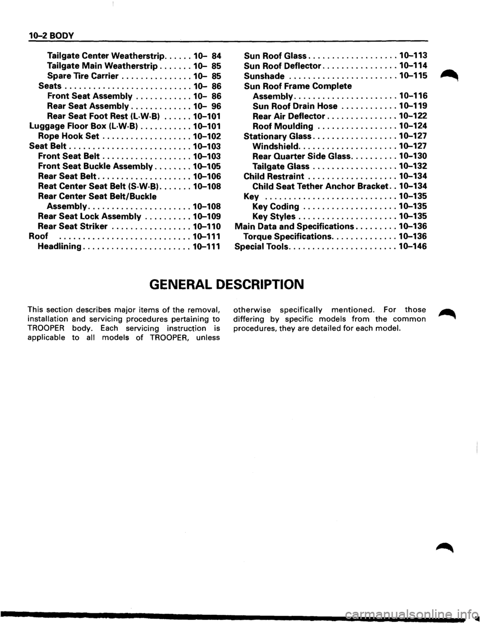
Tailgate Center Weatherstrip ...... 10-84 Sun Roof Glass ................... 10-113
Tailgate Main Weatherstrip ....... 10-85
Spare Tire Carrier
............... 10-85
Sun Roof Deflector ................ 10-114
Sunshade ....................... 10-115 ~
Seats ........................... 10-86 Sun Roof Frame Complete
Front Seat Assembly ............ 10-86 Assembly ...................... 10-116
Rear Seat Assembly ............. 10-96 Sun Roof Drain Hose ............ 10-119
Rear Seat Foot Rest (L·W·B) ...... 10-101 Rear Air Deflector ............... 10-122
Luggage Floor Box (L·W·B) ........... 10-101 Roof Moulding ................. 10-124
Rope Hook Set ................... 10-102 Stationary Glass .................. 10-127
Seat
Belt .......................... 10-103 Windshield ..................... 10-127
Front Seat Belt ................... 10-103 Rear Quarter Side Glass .......... 10-130
Front Seat Buckle Assembly ........ 10-105 Tailgate Glass .................. 10-132
Rear Seat Belt .................... 10-106 Child Restraint ................... 10-134
Reat Center Seat Belt (S·W·B) ....... 10-108 Child Seat Tether Anchor Bracket .. 10-134
Rear Center Seat Belt/Buckle Key ............................ 10-135
Assembly ...................... 10-108 Key
Coding .................... 10-135
Rear Seat Lock Assembly .......... 10-109 Key Styles ..................... 10-135
Rear Seat Striker ................. 10-110 Main Data and Specifications ......... 10-136
Roof ............................ 10-111 Torque Specifications .............. 10-136
Headlining ....................... 10-111 Special Tools ....................... 10-146
GENERAL DESCRIPTION
This section describes major items of the removal,
installation
and servicing procedures pertaining to
TROOPER body. Each servicing instruction is
applicable to all models of TROOPER, unless
otherwise specifically mentioned. For those
differing by specific models from the common
procedures, they are detailed for each model.
..
Page 1792 of 1928
1o-34 BODY
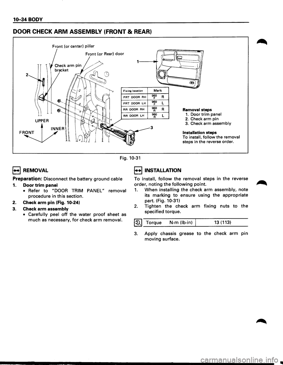
DOOR CHECK ARM ASSEMBLY (FRONT & REAR)
Front (or center) pillar
Front (or Rear) door
2
Fixing location Mark
FRT DOOR RH 960 R F
FRT DOOR LH 960 L F
RR
DOOR RH 960 R R Removal steps
RR DOOR LH 960 L R 1. Door trim panel
3
2. Check arm pin 3. Check arm assembly
Installation steps
To
install, follow the removal
steps in
the reverse order.
Fig. 10-31
1++1 REMOVAL
Preparation:
Disconnect the battery ground cable
1. Door trim panel
• Refer to "DOOR TRIM PANEL" removal
procedure in this section.
2. Check
arm pin (Fig. 10-24)
3. Check arm assembly
• Carefully peel off the water proof sheet as
much as necessary, for check arm removal.
I••IINSTALLATION
To install, follow the removal steps in the reverse
order,
noting the following point.
1. When installing the check arm assembly, note
its marking
to ensure using the appropriate
part. (Fig.
10-31)
2. Tighten the check arm fixing nuts to the
specified torque.
~~~ Torque N-m (lb·in) I 13(113)
3. Apply chassis grease to the check arm pin
moving surface.
..
Page 1799 of 1928
BODY 10-41
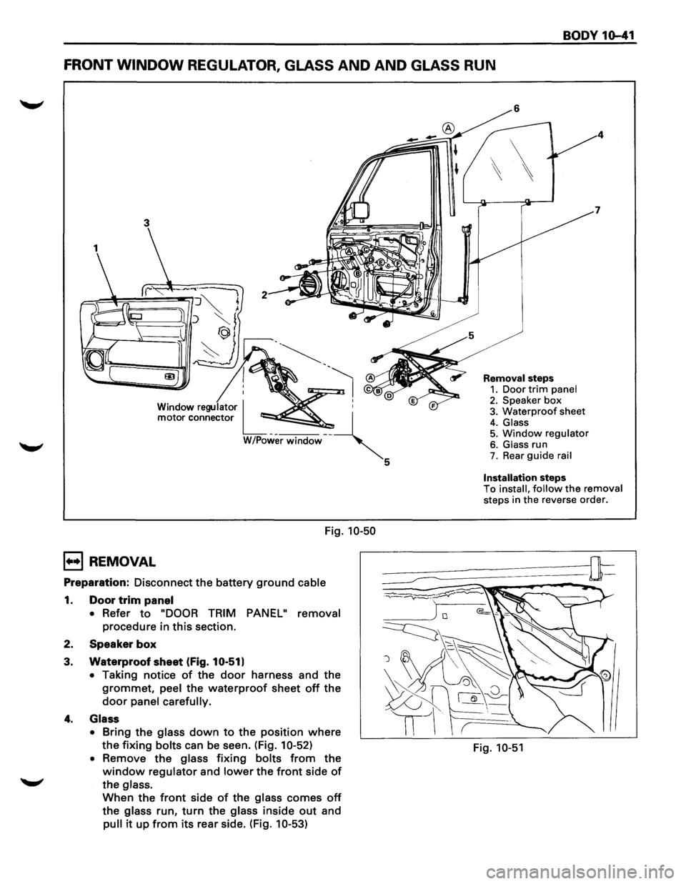
FRONT WINDOW REGULATOR, GLASS AND AND GLASS RUN
3
Window regulator I ~ :
motor connector L__ --~
W/Power window '
Fig. 10-50
B REMOVAL
Preparation: Disconnect the battery ground cable
1. Door trim panel
•
Refer to "DOOR TRIM PANEL" removal
procedure in this section.
2. Speaker
box
3. Waterproof sheet (Fig. 10-51)
•
Taking notice of the door harness and the
grommet, peel the waterproof sheet off the
door panel carefully.
4. Glass
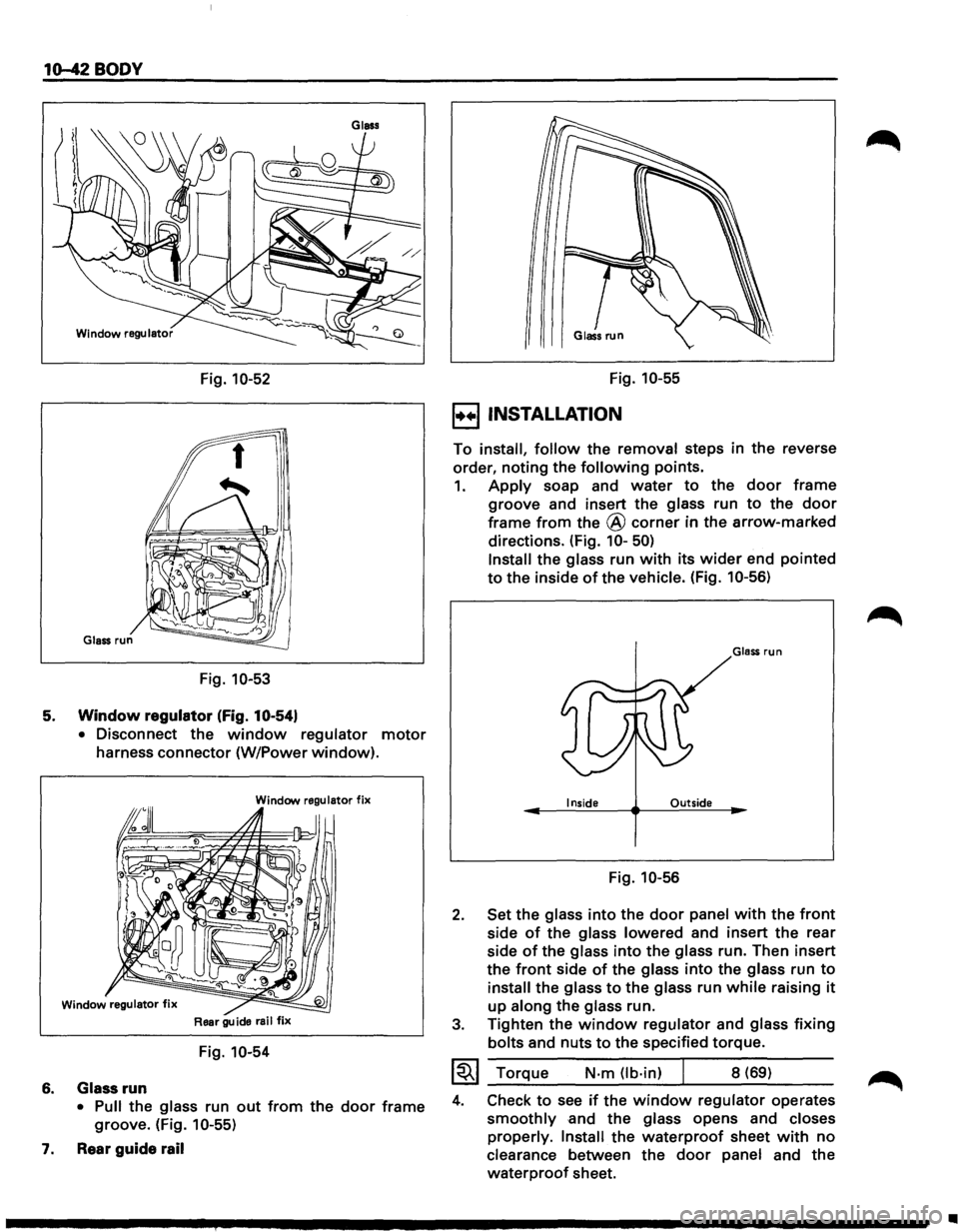
•
Bring the glass down to the position where
the fixing bolts can be seen. (Fig. 10-52)
•
Remove the glass fixing bolts from the
window regulator and lower the front side of
the glass.
When the front side of the glass comes off
the glass run, turn the glass inside out and
pull it up from its rear side. (Fig. 10-53)
5
Removal steps 1. Door trim panel 2. Speaker box 3. Waterproof sheet
4. Glass 5. Window regulator
6. Glass run 7. Rear guide rail
Installation steps To install, follow the removal steps in the reverse order.
Fig. 10-51
Page 1800 of 1928
10-42 BODY
Fig. 10-52
Fig. 10-53
5. Window regulator (Fig. 10-54)
6.
7.
• Disconnect the window regulator motor
harness connector (W/Power window).
Window regulator fix
Rear guide rail fix
Fig. 10-54
Glass
run
• Pull the glass run out from the door frame
groove. (Fig. 10-55)
Rear
guide rail
Fig. 10-55
E) INSTALLATION
To install, follow the removal steps in the reverse
order,
noting the following points.
1. Apply soap and water to the door frame
groove and insert the glass run to the door
frame from the @ corner in the arrow-marked
directions. (Fig.
10-50)
2.
3.
Install the glass run with its wider end pointed
to the inside of the vehicle. (Fig. 10-56)
Glass run
Inside Outside
Fig. 10-56
Set the glass
into the door panel with the front
side of the glass lowered and insert the rear
side
of the glass into the glass run. Then insert
the
front side of the glass into the glass run to
install the glass to the glass run while raising it
up along the glass run.
Tighten the
window regulator and glass fixing
bolts and nuts to the specified torque.
~~~ _T_o_r~q_u_e ____ N_·m __ (l_b_·i_n) __ ~ ___ 8_(_6_9_) ____ _
4. Check to see if the window regulator operates
smoothly and the glass opens and closes
properly.
Install the waterproof sheet with no
clearance between the door panel and the
waterproof sheet.
•
Page 1801 of 1928
REAR WINDOW REGULATOR AND GLASS
W/0 Power window r----------~
I I I ;...1 ... ----4
I I
I
I
I I
I I
I I L ______ ----_j
2
Fig. 10-57
1••1 REMOVAL
Preparation: Disconnect the battery ground cable
1. Door trim panel
•
Refer to "DOOR TRIM PANEL (REAR)"
removal procedure in this section.
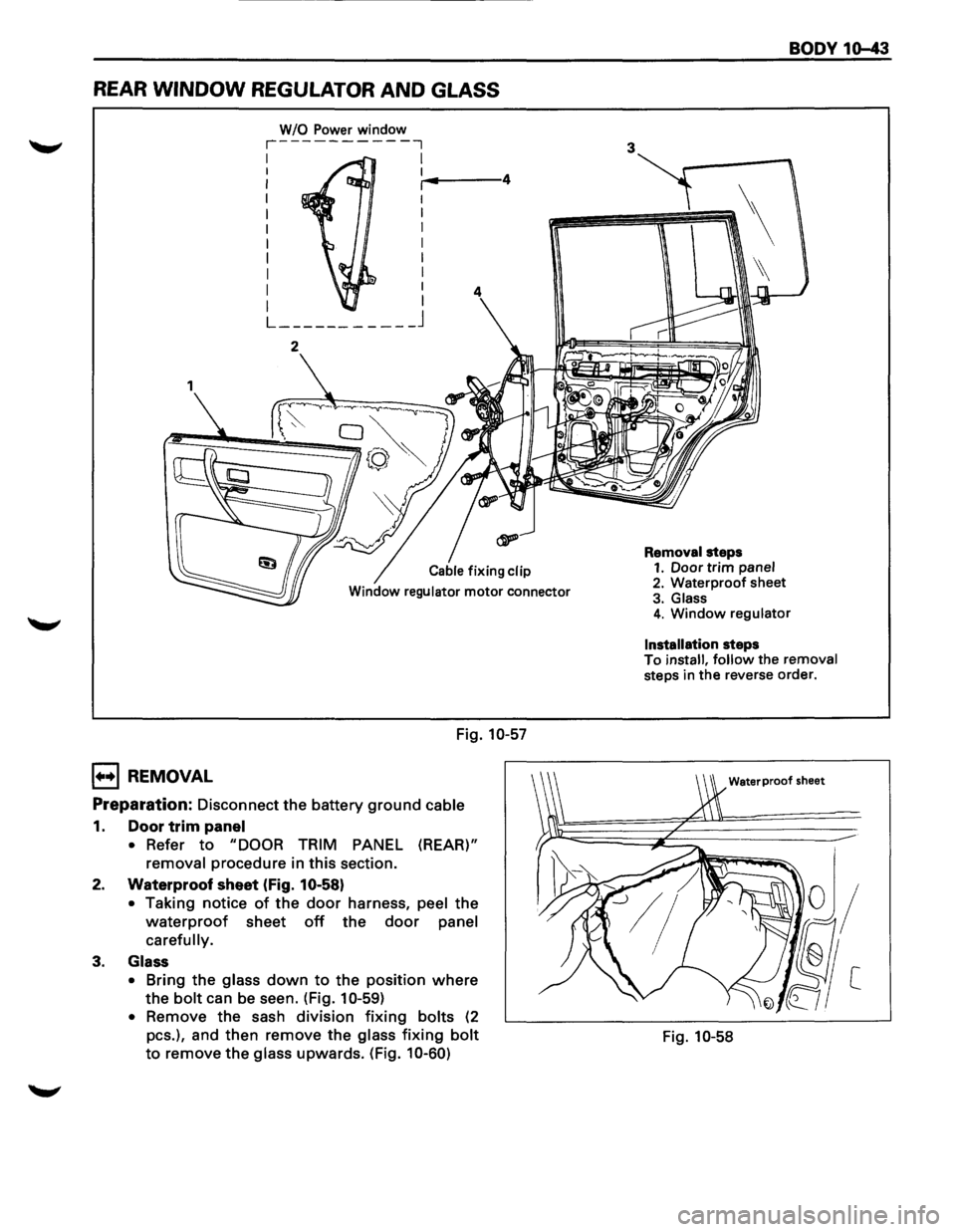
2. Waterproof sheet (Fig. 10-58)
• Taking notice of the door harness, peel the
waterproof sheet off the door panel
carefully.
3. Glass
•
Bring the glass down to the position where
the bolt can be seen. (Fig. 1 0-59)
•
Remove the sash division fixing bolts (2
pes.), and then remove the glass fixing bolt
to remove the glass upwards. (Fig. 10-60)
3
BODY 10-43
Removal steps 1. Door trim panel 2. Waterproof sheet
3. Glass 4. Window regulator
Installation
steps
To install, follow the removal steps in the reverse order.
Fig. 10-58
Page 1802 of 1928
10-44 BODY
A B
Fig. 10-59
Fig. 10-60
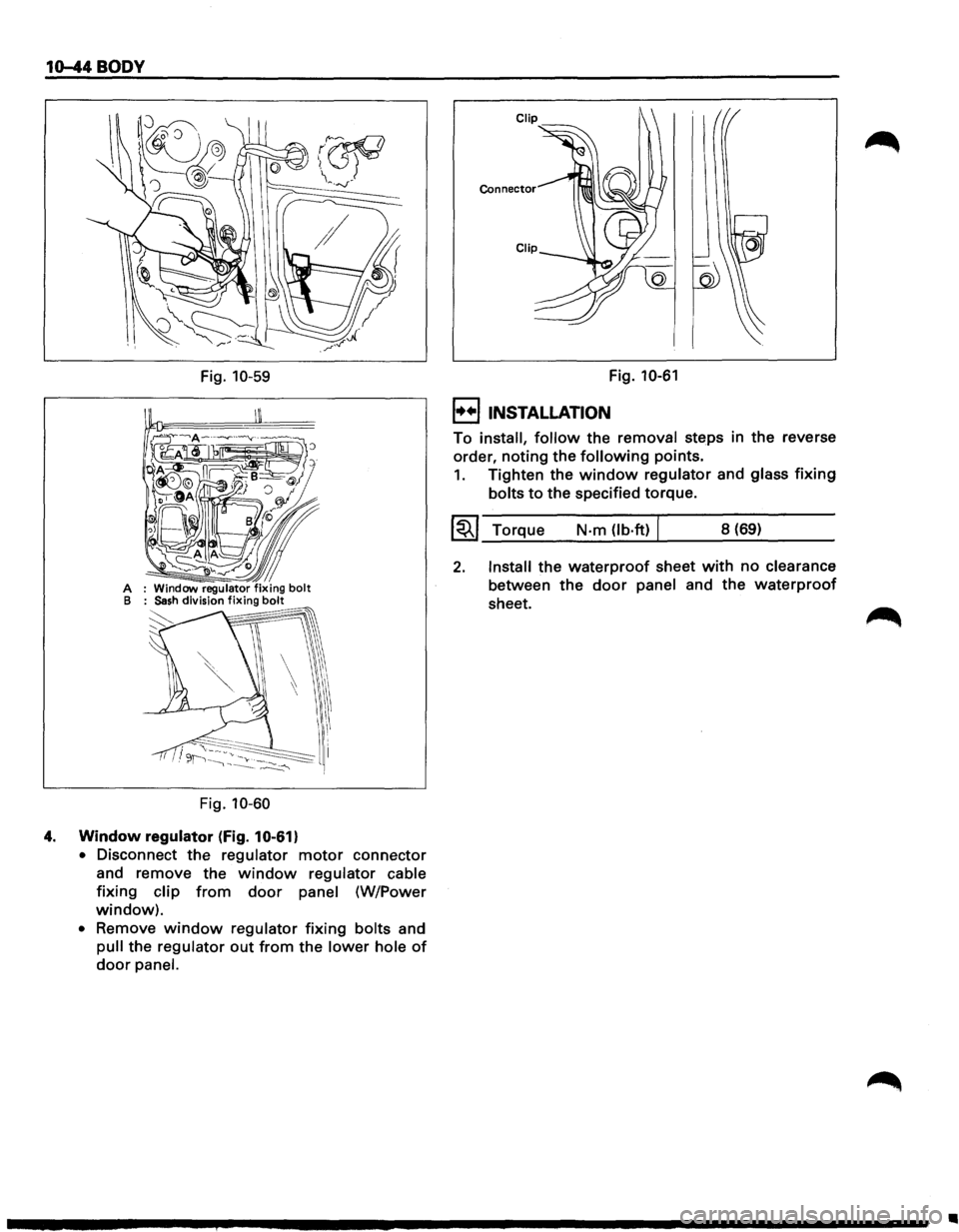
4. Window regulator (fig. 10-61)
• Disconnect the regulator motor connector
and remove the
window regulator cable
fixing clip from door panel (W/Power
window).
• Remove window regulator fixing bolts and
pull the regulator
out from the lower hole of
door panel. Fig.
10-61
I••! INSTALLATION
To
install, follow the removal steps in the reverse
order,
noting the following points.
1. Tighten the window regulator and glass fixing
bolts to the specified torque.
~~~ Torque N·m (lb·ft) I 8 (69)
2. Install the waterproof sheet with no clearance
between
the door panel and the waterproof
sheet.
•
Page 1803 of 1928
FRONT DOOR LOCK ASSEMBLY
2 Outside handle ...
Door lock switch
connector
(W/Power
door lock)
Fig. 10-62
1++1 REMOVAL
Preparation: Disconnect the battery ground cable
1. Door trim panel
2. Waterproof sheet
• Refer to "WINDOW REGULATOR" removal
procedure in this section.
3. Rear
guide rail
•
Raise the glass up to the uppermost position.
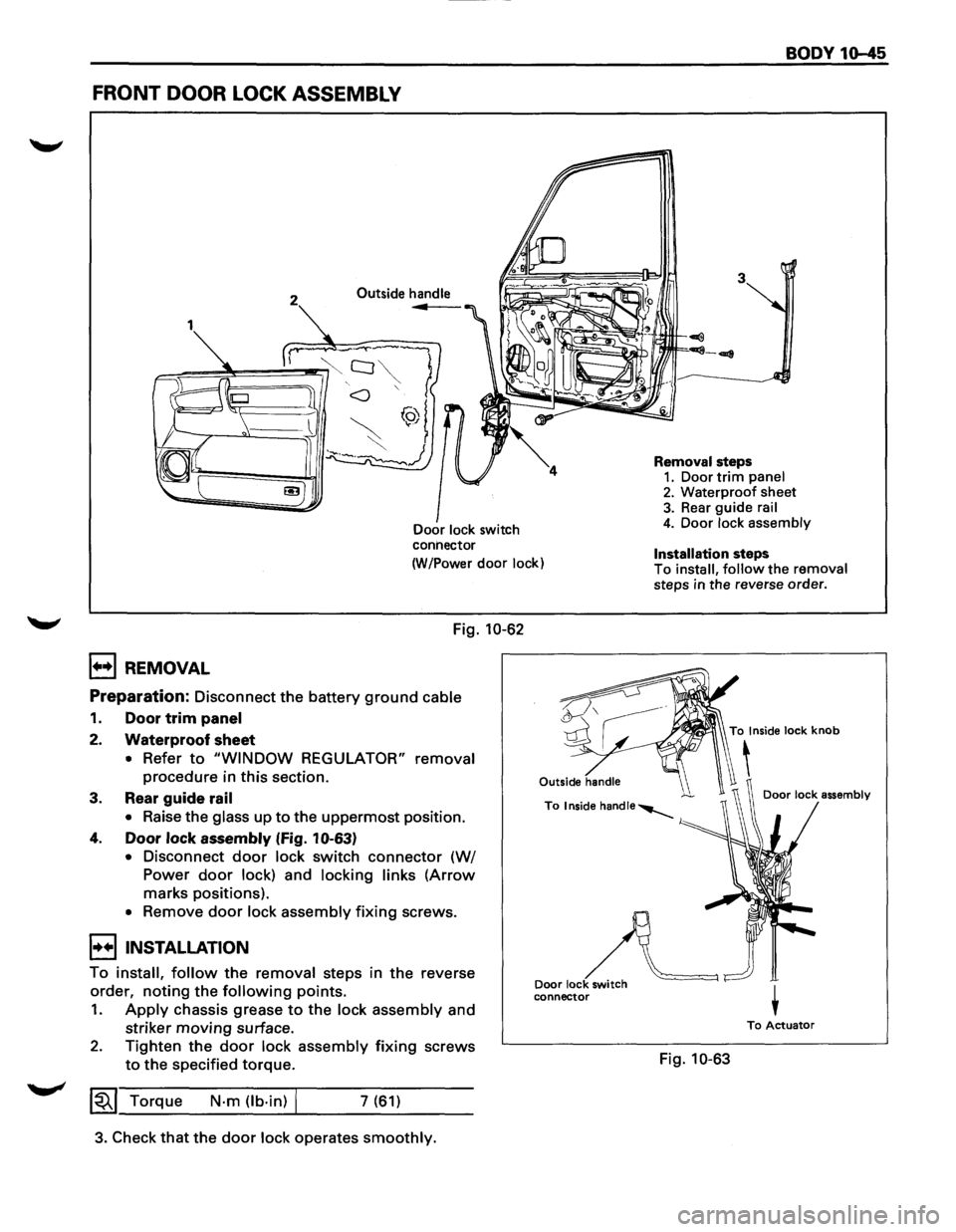
4. Door lock assembly (Fig. 10-63)
• Disconnect door lock switch connector (W/
Power
door lock) and locking links (Arrow
marks positions).
• Remove door lock assembly fixing screws.
I++IINSTALLATION
To install, follow the removal steps in the reverse
order, noting the following points.
1. Apply chassis grease to the lock assembly and
striker
moving surface.
2. Tighten the door lock assembly fixing screws
to the specified torque.
~~~ Torque N·m Ob·in) I 7 (61)
3. Check that the door lock operates smoothly.
Outside handle
Door lock switch
connector
BODY 10-45
Removal steps 1. Door trim panel 2. Waterproof sheet 3. Rear guide rail 4. Door lock assembly
Installation steps To install, follow the removal steps in the reverse order.
To Inside lock knob
'
To Actuator
Fig. 10-63
Page 1804 of 1928
10-46 BODY
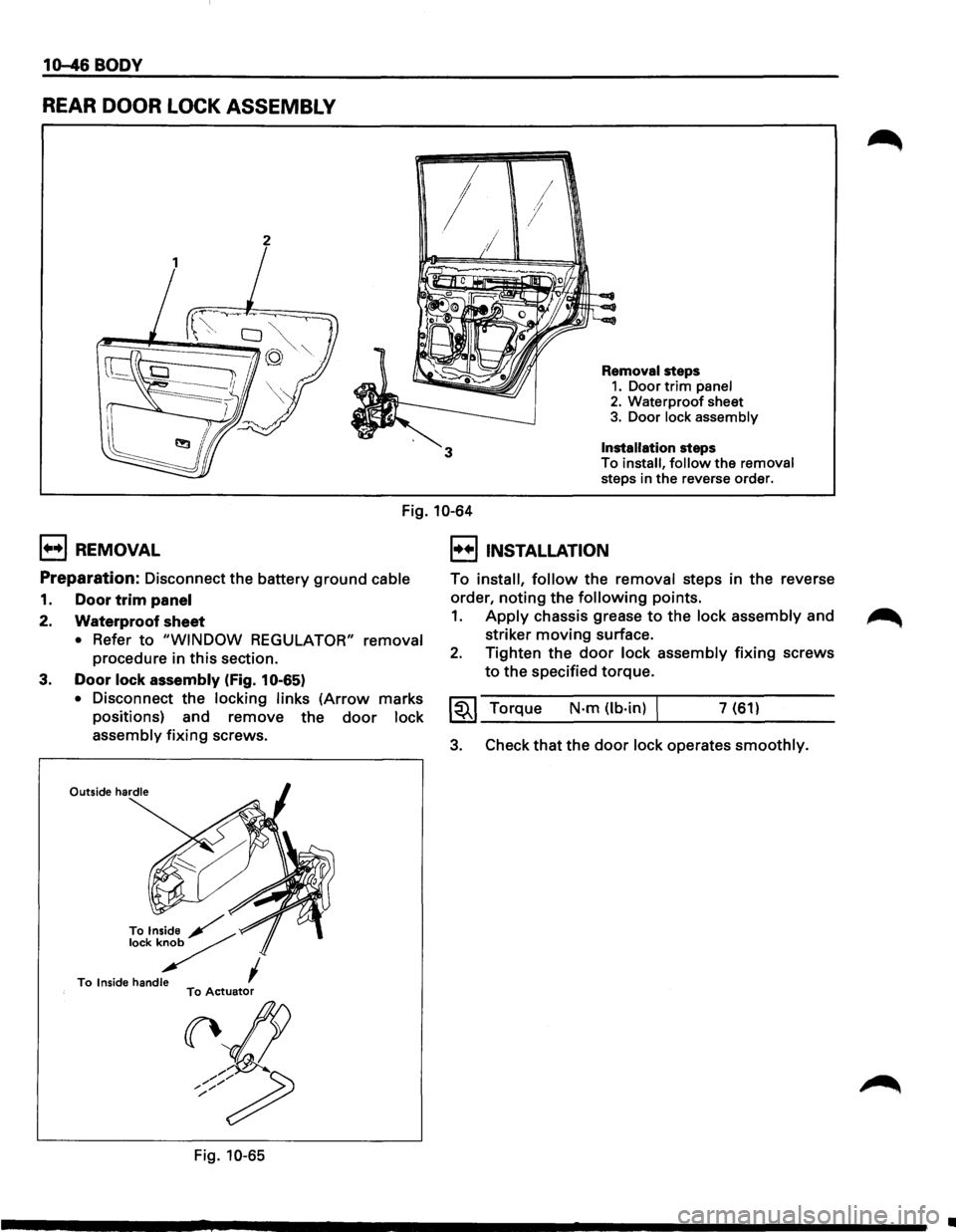
REAR DOOR LOCK ASSEMBLY
2
3
Removal steps
1. Door trim panel 2. Waterproof sheet 3. Door lock assembly
Installation steps To install, follow the removal
steps in the reverse order.
1++1 REMOVAL
Fig. 10-64
I++IINSTALLATION
Preparation: Disconnect the battery ground cable
1. Door trim panel
2. Waterproof sheet
• Refer to "WINDOW REGULATOR" removal
procedure in this section.
3. Door lock assembly (Fig. 10-65)
• Disconnect the locking links (Arrow marks
positions) and remove the
door lock
assembly
fixing screws.
Tolns~~~~ lockk/
To Inside handle I To Actuator
((\/Z
----~
/ / / / /
Fig. 10-65
To install, follow the removal steps in the reverse
order,
noting the following points.
1. Apply chassis grease to the lock assembly and
striker
moving surface.
2. Tighten the door lock assembly fixing screws
to the specified torque.
~~~ Torque N-m (lb·in) I 7 (61)
3. Check that the door lock operates smoothly.
•
Page 1805 of 1928
BODY 16-47
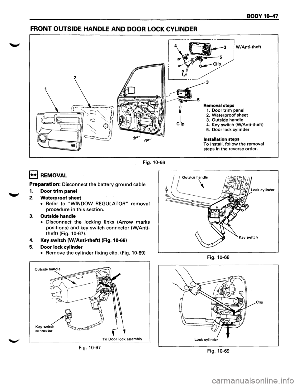
FRONT OUTSIDE HANDLE AND DOOR LOCK CYLINDER
Fig. 10-66
1+•1 REMOVAL
Preparation: Disconnect the battery ground cable
1. Door trim panel
2. Waterproof sheet
• Refer to "WINDOW REGULATOR" removal
procedure in this section.
3. Outside handle
• Disconnect the locking links (Arrow marks
positions) and key
switch connector (W/Anti
theft) (Fig. 10-67).
4. Key switch (W/Anti-theft) (fig. 10-68)
5. Door lock cylinder
• Remove the cylinder fixing clip. (Fig. 10-69)
K~~'~ connector
To Door lock assembly
Fig. 10-67
Installation steps
To install, follow the removal steps in the reverse order.
Outside handle
Fig. 10-68
Clip
Fig. 10-69