I••! INSTALLATION
"-" ___. Primer
~ Sealing adhesive Tailgate frame
3 mm
(0.12 in.) 9mm (0.35 in.)
BODY 10-133
Tailgate glass
-Glass moulding .~
Tailgate glass
SECTION A-A
Tailgate glass
®
.....
"" 8 y;=::J..r«~~ '----+--~>---+---"-'• E .____ ---E N
15m~ (0.59 in.)
(Glass side)
Glass primer coating area
9 mm (0.35 in.)
SECTION B-B
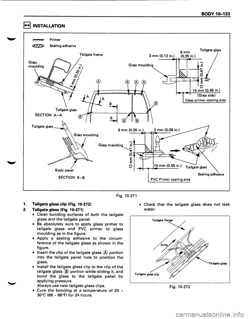
Fig. 10-271
1. Tailgate glass clip (Fig. 10-2721
2. Tailgate glass (Fig. 10-2711
• Clean bonding surfaces of both the tailgate
glass
and the tailgate panel.
•
Be absolutely sure to apply glass primer to
tailgate glass and PVC primer to glass
moulding as in the figure.
• Apply a sealing adhesive to the circum
ference of the tailgate glass as shown in the
figure.
• Insert the clip of the tailgate glass @ portion
into the tailgate panel hole to position the
glass.
• Install
the tailgate glass clip to the clip of the
tailgate glass @ portion while sliding it, and
bond the glass to the tailgate panel by
applying pressure.
Always use new tailgate glass clips.
• Cure
the bonding at a temperature of 20 -
30°C
(68 - 86°F) for 24 hours.
14 mm (0.5 5 in.)
Tailgate glass
Sealing adhesive
PVC Primer coating area
• Check that the tailgate glass does not leak
water.
Tailgate flange
Tailgate glass
Fig. 10-272
BODY 1Q-135
KEY
KEY CODING
KEY USAGE AND IDENTIFICATION
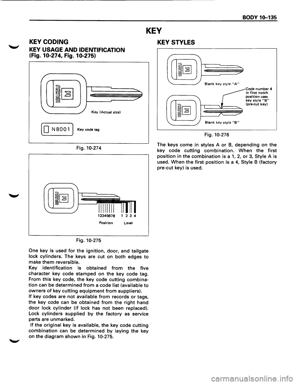
(Fig. 10-274, Fig. 10-275)
I
Key (Actual size)
( 0 N8001) Keycodetag
Fig. 10-274
12345678 1 2 3 4
Position Level
Fig. 10-275
One
key is used for the ignition, door, and tailgate
lock cylinders.
The keys are cut on both edges to
make them reversible.
Key identification is obtained from the five
character key code stamped on
the key code tag.
From
this key code, the key code cutting combina
tion can be determined from a code list (available to
owners of key cutting equipment from suppliers).
If key codes are not available from records or tags,
the key code can be obtained
from the right hand
door lock cylinder (if lock has not been replaced).
Lock cylinders supplied by the factory as service
parts are unmarked.
If the original key is available, the key code cutting
combination can be determined by laying the key
on the diagram
shown in Fig. 10-275.
KEY STYLES
Blank key style "A"
Blank key style "B"
Fig. 10-276
Code number 4
in first notch position uses key style "B" (pre-cut key)
The keys come in styles A or 8, depending on the
key code cutting combination. When the
first
position in the combination is a 1, 2, or 3, Style A is
used. When the
first position is a 4, Style 8 (factory
pre-cut key) is used.