JAGUAR X308 1998 2.G Owners Manual
X308 1998 2.G
JAGUAR
JAGUAR
https://www.carmanualsonline.info/img/21/7640/w960_7640-0.png
JAGUAR X308 1998 2.G Owners Manual
Page 203 of 2490
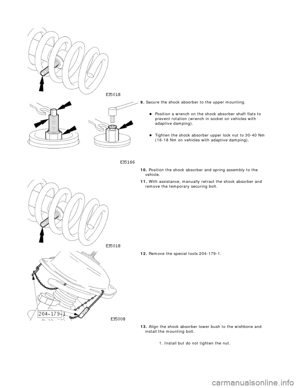
9. Se
cure the shock absorber
to the upper mounting.
Posi
tion a wrench on the shock absorber shaft flats to
prevent rotation (wrench in socket on vehicles with
adaptive damping).
Tigh
ten the shock absorber upper lock nut to 30-40 Nm
(16-18 Nm on vehicles with adaptive damping).
10. Position the shock absorber and spring assembly to the
vehicle.
11
.
With assistance, manually re tract the shock absorber and
remove the temporary securing bolt.
12
.
Remove the special tools 204-179-1.
13. Align the shock absorber lower bush to the wishbone and
install the mounting bolt.
1. Install but do not tighten the nut.
Page 205 of 2490
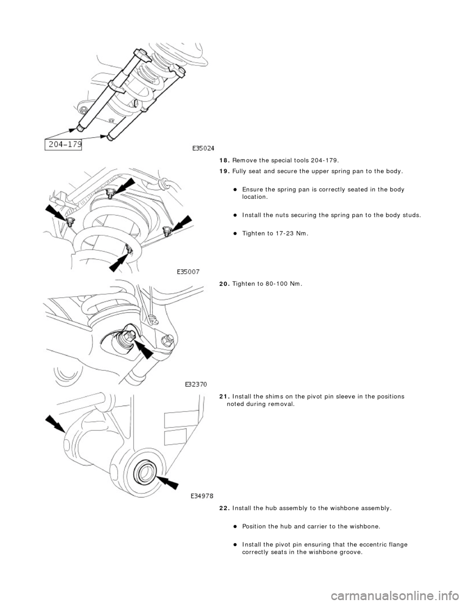
18
.
Remove the special tools 204-179.
19
.
Fully seat and secure the u pper spring pan to the body.
Ensure the spri
ng pan is correctly seated in the body
location.
Inst
all the nuts securing the sp
ring pan to the body studs.
Tigh
ten to 17-23 Nm.
20
.
Tighten to 80-100 Nm.
21
.
Install the shims on the pivot pin sleeve in the positions
noted during removal.
22. Install the hub assembly to the wishbone assembly.
Position the hub and carri
er to the wishbone.
Inst
all the pivot pin ensuring that the ecce
ntric flange
correctly seats in the wishbone groove.
Page 206 of 2490
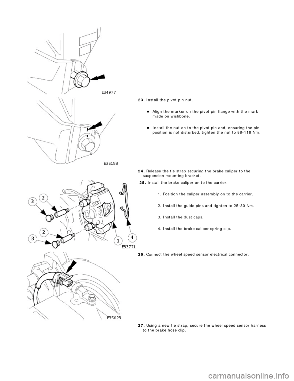
23. Inst
all the pivot pin nut.
Ali
g
n the marker on the pivo
t pin flange with the mark
made on wishbone.
Inst al
l the nut on to the pivot pin and, ensuring the pin
position is not dist urbed, tighten the nut to 88-118 Nm.
24. Release the tie strap securing the brake caliper to the
suspension mounting bracket.
25 . Install
the brake caliper on to the carrier.
1. Position the caliper asse mbly on to the carrier.
2. Install the guide pins and tighten to 25-30 Nm.
3. Install the dust caps.
4. Install the brake caliper spring clip.
26 . Conne
ct the wheel speed sensor electrical connector.
27. Using a new tie strap, secure the wheel speed sensor harness
to the brake hose clip.
Page 208 of 2490
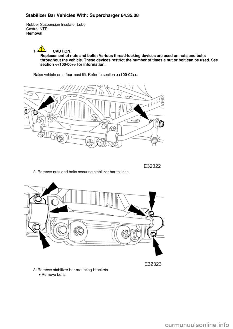
St
abilizer Bar Vehicles With: Supercharger
64.35.08
Rubber Suspension Insulator Lube
Castrol NTR
Removal
1.
CA
UTION:
Replacement of nuts and bolts: Various thread-locking devices are used on nuts and bolts
throughout the vehicle. These devices restrict the number of times a nut or bolt can be used. See
section <<100-00>>
for information.
Raise vehicle on a four-post lift. Refer to section <<100-02>>.
2.
Remove nuts and bolts securing stabilizer bar to links.
3.
Remove stabilizer bar mounting-brackets.
Remove bolts.
Page 211 of 2490
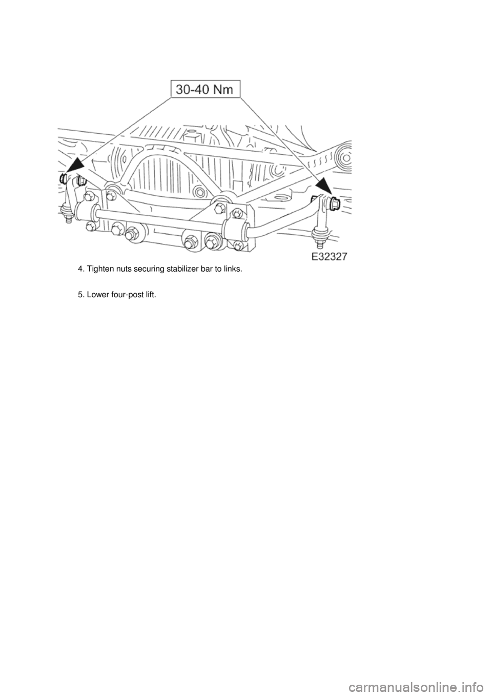
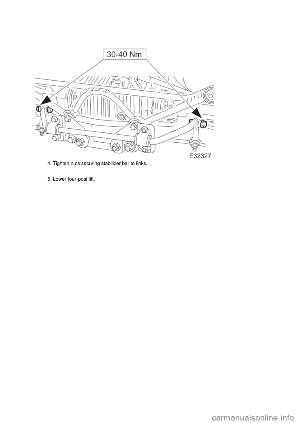
4
. Tighten nuts securing stabilizer bar to links.
5. Lower four-post lift.
Page 214 of 2490
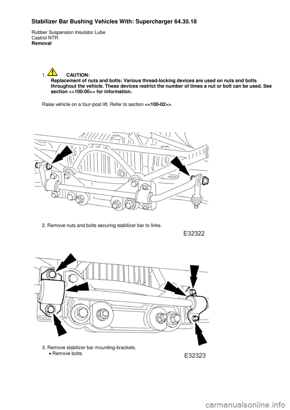
St
abilizer Bar Bushing Vehicles With: Supercharger
64.35.18
Rubber Suspension Insulator Lube
Castrol NTR
Removal
1.
CA
UTION:
Replacement of nuts and bolts: Various thread-locking devices are used on nuts and bolts
throughout the vehicle. These devices restrict the number of times a nut or bolt can be used. See
section <<100-00>>
for information.
Raise vehicle on a four-post lift. Refer to section <<100-02>>.
2.
Remove nuts and bolts securing stabilizer bar to links.
3.
Remove stabilizer bar mounting-brackets.
Remove bolts.
Page 217 of 2490
4
. Tighten nuts securing stabilizer bar to links.
5. Lower four-post lift.
Page 218 of 2490
Rear Suspension - Stabilizer Bar Mounting Frame
Remo
val and Installation
Remov
a
l
CAUTI
O
N: Replacement of
nuts and bolts: Various thread-locking devices are used on nuts and bolts throughout the
vehicle. These devices restrict the number of times a nut or bolt can be used. See section 100-00 for information.
1. Ra
ise rear of vehicle and support
on stands. Refer to Section
100-02.
2. Support rear suspensio
n.
Posit
i
on a piece of wood under rear edge of suspension
unit.
Position an d
raise a jack
under wood to support
suspension unit.
3. Re
move monostrut lowe
r nuts and bolts.
4. Remove m
onostrut upper mounting
to body bracket securing
bolts.
5. Remove monostrut.
Lower rear edg
e
of suspension unit just sufficient for
access.
Exercising care to avoid dama ging fuel fil
ler neck drain
pipe, lift and withdraw monost rut from rear suspension.
Page 223 of 2490
9. P
osition special tool 204-195 on hub studs and install securing
nuts.
10
.
Slacken but do not remove hub to axle shaft securing nut.
11. Remove securing nuts and withdraw special tool (204-195)
from hub.
12. Remove rear brake disc. Refer to 70.10.13.
13. Remove parking brake shoe s. Refer to 70.40.05.
14
.
Remove wheel speed sensor.
Disc
onnect wheel speed sensor harness from sensor
R
emove wheel speed sensor se
curing bolt and withdraw
sensor from hub carrier.
15
.
Sever and discard wheel speed sensor harness tie strap and
position harness for access.
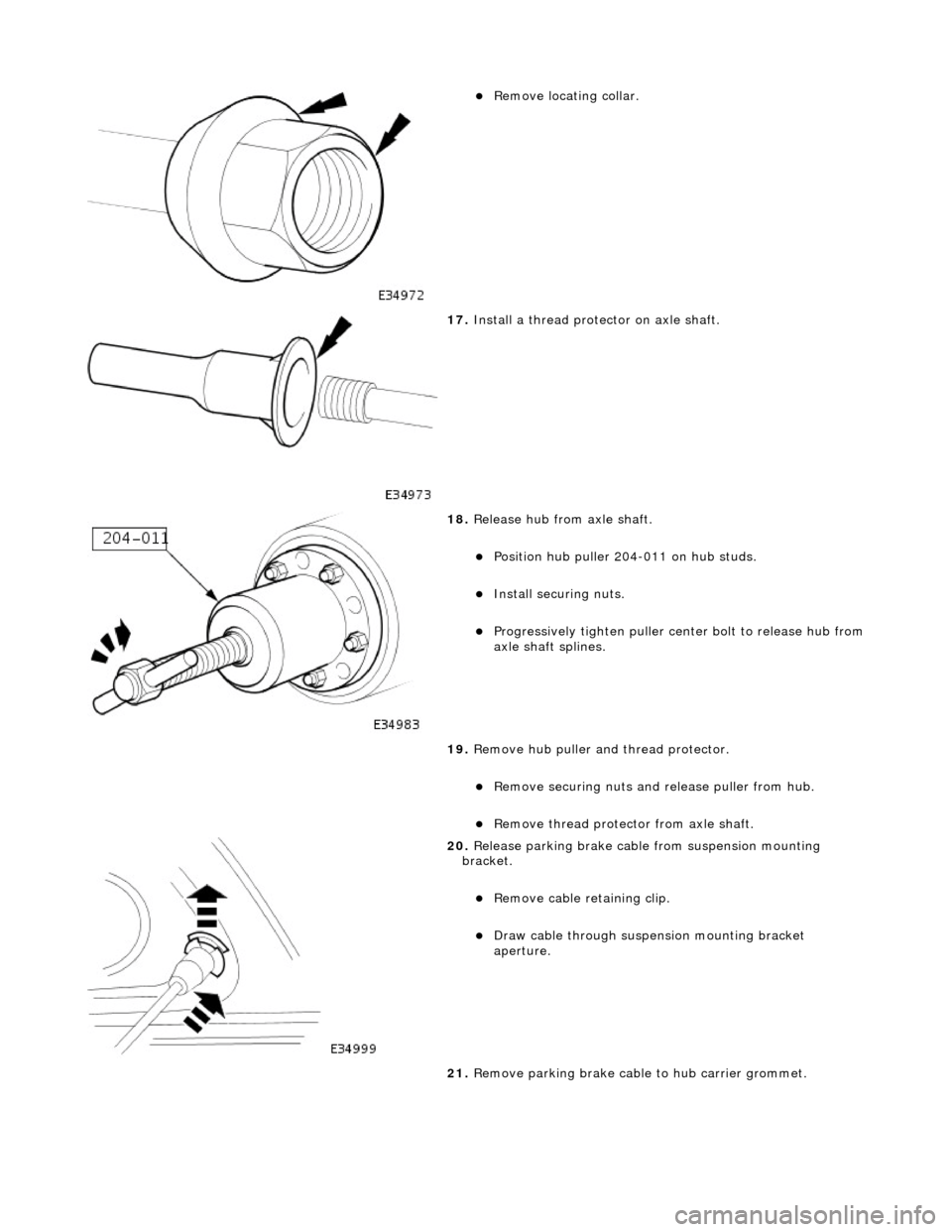
16. Remove hub nut and collar.
Re
move nut.
Page 224 of 2490
Remove l
ocating collar.
17 . Install a th
read protector on axle shaft.
18 . R
elease hub from axle shaft.
Pos
i
tion hub puller 204-011 on hub studs.
Inst
al
l securing nuts.
Progres
s
ively tighten
puller center bolt to release hub from
axle shaft splines.
19. Remove hub puller an d thread protector.
Re
move securing nuts and
release puller from hub.
Re
move thread protecto
r from axle shaft.
20 . Relea
se parking brake cable
from suspension mounting
bracket.
Remove cable reta ining clip.
Draw c
a
ble through suspension mounting bracket
aperture.
21. Remove parking brake cable to hub carrier grommet.
