ECU JAGUAR X308 1998 2.G Repair Manual
[x] Cancel search | Manufacturer: JAGUAR, Model Year: 1998, Model line: X308, Model: JAGUAR X308 1998 2.GPages: 2490, PDF Size: 69.81 MB
Page 131 of 2490

I
nstallation
14
.
To prevent damage to lower ball joint, secure vertical link to
road spring using strong wire.
15
.
Remove upper wishbone fulcrum nut and shaft and withdraw
wishbone from crossbeam.
16. Secure upper wishbone in a vise.
17
.
Remove bush assemblies from wishbone.
1. Using a drift, remove thru st washer and spacer tube
from each inner and outer half-bush.
2. Remove inner and outer half bushes from wishbone.
Repeat
procedure to remove
remaining bush assembly.
18. Clean wishbone paying particular attention to bush locations.
19. Check that ball joint gaiter is not punctured or deeply
abraded.
1. Install thrust washer and spacer tube in first wishbone half-
bush.
Page 132 of 2490

2. Apply a su
itable lubricant to exterior of each half-bush.
3. Install soft covers to vise jaws.
4. Install half-bush
/spacer tu
be assembly in wishbone.
1. Align half-bush/spacer tube assembly with wishbone bore.
2. Position wishbone and half bush/spacer tube assembly between vise jaws.
Cl
ose vise jaws until half-bush/tube assembly is fully
seated in wishbone.
5. Remove wishbone from vise.
6. Instal
l second half-bush in wishbone.
1. Align and engage second half-bush with installed
spacer tube.
2. Position wishbone and half bush assembly between vise jaws.
Close
vise jaws until second half-bush assembly is fully
seated.
7. Remove wishbone from vise.
8. Following steps 1 to 7, install final bush assembly to wishbone.
9. Inst al
l wishbone on crossbeam.
Posi
ti
on wishbone on crossbeam.
Install
fulcrum shaft with threaded end rearward.
Install nut an
d tighten to 60-80Nm.
10. Remove wire temporarily securing vertical link to road spring.
Page 133 of 2490

11
.
Position wishbone to engage ball joint taper in vertical link.
12
.
Install nut securing ball joint to vertical link and tighten nut to
60-80Nm.
13
.
Reposition wheel speed sensor harness on wishbone and
secure with two tiestraps.
14. Fit road wheel. Refer to Section 100-02
15. Raise vehicle, remove stands and fully lower vehicle.
16. Fully slacken nut on special tool.
Page 136 of 2490

Remova
l
CAUTI
O
N: Replacement of
nuts and bolts: Various thread-locking devises are used on nuts and bolts throughout the
vehicle. These devises restrict the number of times a nut or bolt can be used. See section 100-00 for information.
1 8
G 1004
1.
Re
move vertical link and hub as
sembly. Refer to 60.25.38.90.
2. Re
move brake disc shield from vertical link.
1. Remove screws.
2. Remove disc shield.
3. Us
ing special tool, secure vertical link and hub assembly in a
vise.
Secure special tool
in a vise.
Posit
i
on hub in tool.
Inst
al
l wheel nuts.
4. Re
move rotor nut spring-clip.
5. Remove rotor nut.
Us
ing special tool 206-066A remove rotor nut.
Page 139 of 2490

Inst
all inboard circli
p in vertical link.
5. U
sing a hydraulic press, install hub in vertical link.
1. Position special tool on press bed.
2. Position the vertical link on the tool, with the inboard-side face down.
3. Position hub on bearing.
4. Position a flat steel plate across the face of the hub,
DO NOT place plate ac ross wheel studs.
5. Operate press to install the hub, applying a three-ton
load to ensure hub is fully seated in bearing.
6. U
sing special tool, secure vertical link and hub assembly in a
vise.
Secure special
tool in a vise.
Posit
ion hub in tool.
Inst
all wheel nuts.
7. Install
rotor nut .
1. Install rotor nut on hub.
2. Using special tool tighten rotor nut.
8. CAUTION: Do not slacken the rotor nut to engage the
spring clip.
• NOTE: If the castellated slots of the rotor nut are not aligned,
tighten the rotor nut further unti l the spring clip engages the
Page 142 of 2490

Remova
l
CAUTI
O
N: Replacement of
nuts and bolts: Various thread-locking devises are used on nuts and bolts throughout the
vehicle. These devises restrict the number of times a nut or bolt can be used. Refer to Section 100-00 for further
information.
1 8
G 1004
1.
Ra
ise front of vehicle and support on stands. Refer to Section
100-02.
2. Remove appropriate road wheel. Refer to Section 100-02.
3. Remove front brake disc. Refer to 70.10.12.
4. Remove vertical link and hub assembly. Refer to operation
60.25.38.90.
5. Re
move brake-disc shield from vertical link.
1. Remove screws.
2. Remove disc shield.
6. Us
ing special tool, secure vertical link and hub assembly in a
vise.
Secu re spe
cial tool 204-195 in a vise.
Posit
i
on hub in tool.
Inst
al
l wheel nuts.
7. Remove rotor nut spring-clip.
Page 145 of 2490

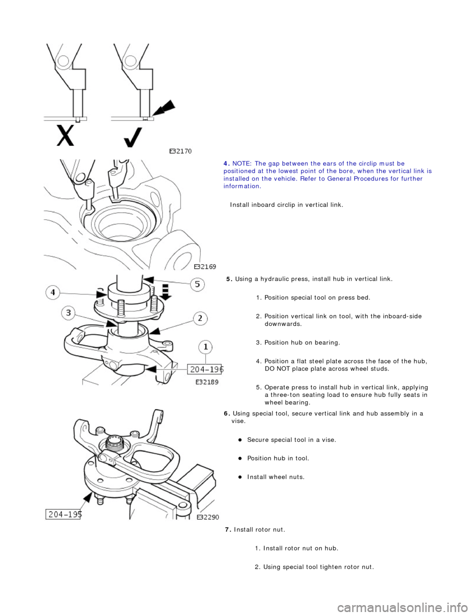
4. NOTE
: The gap between the ears of the circlip must be
positioned at the lowest point of the bore, when the vertical link is
installed on the vehicl e. Refer to General Procedures for further
information.
Install inboard circli p in vertical link.
5. U
sing a hydraulic press, install hub in vertical link.
1. Position special tool on press bed.
2. Position vertical link on tool, with the inboard-side downwards.
3. Position hub on bearing.
4. Position a flat steel plate across the face of the hub,
DO NOT place plate ac ross wheel studs.
5. Operate press to install hu b in vertical link, applying
a three-ton seating load to ensure hub fully seats in
wheel bearing.
6. U
sing special tool, secure vertical link and hub assembly in a
vise.
Secure special
tool in a vise.
Posit
ion hub in tool.
Inst
all wheel nuts.
7. Install rotor nut.
1. Install rotor nut on hub.
2. Using special tool tighten rotor nut.
Page 148 of 2490

Remova
l
CAUTI
O
N: Replacement of
nuts and bolts: Various thread-locking devises are used on nuts and bolts throughout the
vehicle. These devises restrict the number of times a nut or bolt can be used. See section 100-00 for information.
1 8
G 1004
1.
Ra
ise front of vehicle and support on stands. Refer to Section
100-02.
2. Remove appropriate road wheel. Refer to Section 100-02.
3. Remove front brake disc. Refer to 70.10.12.
4. Remove vertical link and hub assembly. Refer to operation
60.25.38.90.
5. Re
move brake-disc shield from vertical link.
1. Remove screws.
2. Remove disc shield.
6. Us
ing special tool, secure vertical link and hub assembly in a
vise.
Secure special tool
in a vise.
Posit
i
on hub in tool.
Inst
al
l wheel nuts.
7. Re
move rotor nut spring-clip.
Page 151 of 2490

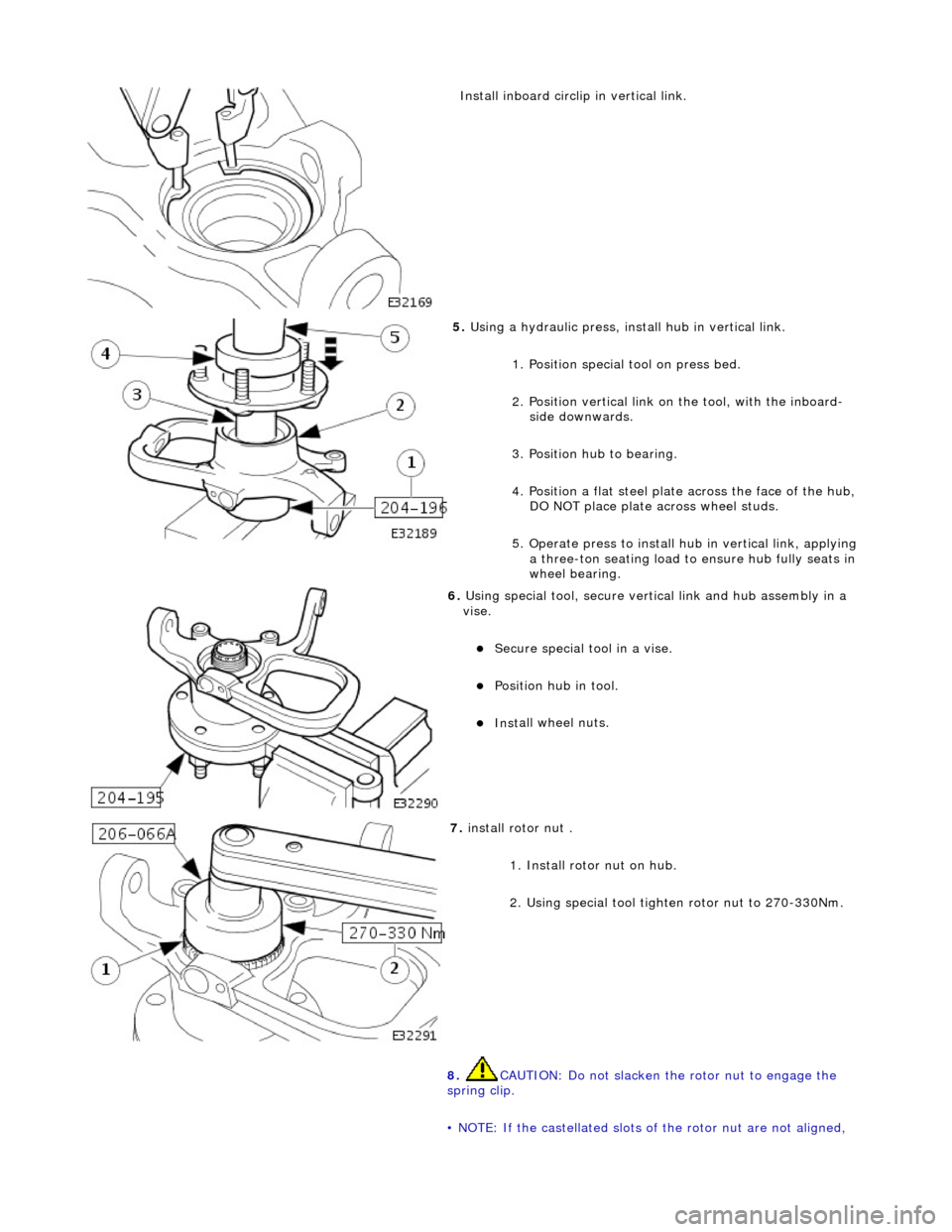
Inst
all inboard circli
p in vertical link.
5. U
sing a hydraulic press, install hub in vertical link.
1. Position special tool on press bed.
2. Position vertical link on the tool, with the inboard-side downwards.
3. Position hub to bearing.
4. Position a flat steel plate across the face of the hub,
DO NOT place plate ac ross wheel studs.
5. Operate press to install hu b in vertical link, applying
a three-ton seating load to ensure hub fully seats in
wheel bearing.
6. U
sing special tool, secure vertical link and hub assembly in a
vise.
Secure special
tool in a vise.
Posit
ion hub in tool.
Inst
all wheel nuts.
7. i
nstall rotor nut .
1. Install rotor nut on hub.
2. Using special tool tighten rotor nut to 270-330Nm.
8. CAUTION: Do not slacken the rotor nut to engage the
spring clip.
• NOTE: If the castellated slots of the rotor nut are not aligned,
Page 153 of 2490

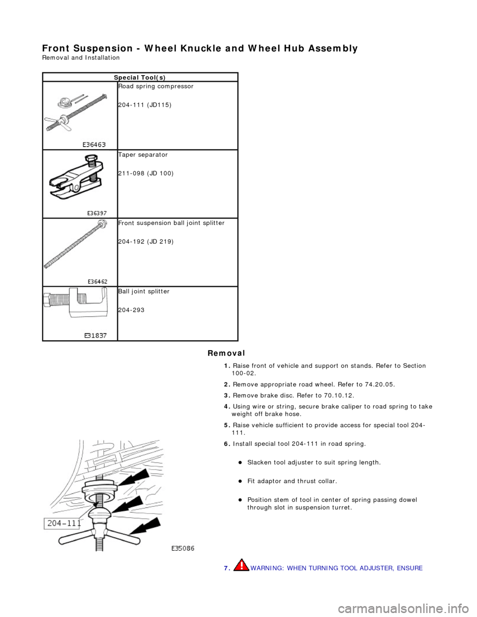
Front Susp
ension - Wheel Knuckle and Wheel Hub Assembly
Re
moval and Installation
Remov
al
S
pecial Tool(s)
R
oad spring compressor
204-111 (JD115)
Taper separator
211-098 (JD 100)
Front
suspension ball joint splitter
204-192 (JD 219)
Bal
l joint splitter
204-293
1. Raise front of vehicle and support on stands. Refer to Section
100-02.
2. Remove appropriate road wheel. Refer to 74.20.05.
3. Remove brake disc. Refer to 70.10.12.
4. Using wire or string, secure brak e caliper to road spring to take
weight off brake hose.
5. Raise vehicle sufficient to provide access for special tool 204-
111.
6. Ins
tall special tool 204-111 in road spring.
Sl
acken tool adjuster to suit spring length.
Fit adaptor and th
rust collar.
Posit
ion stem of tool in center of spring passing dowel
through slot in su spension turret.
7. WARNING: WHEN TURNING TOOL ADJUSTER, ENSURE