Suspension JAGUAR X308 1998 2.G Owners Manual
[x] Cancel search | Manufacturer: JAGUAR, Model Year: 1998, Model line: X308, Model: JAGUAR X308 1998 2.GPages: 2490, PDF Size: 69.81 MB
Page 312 of 2490
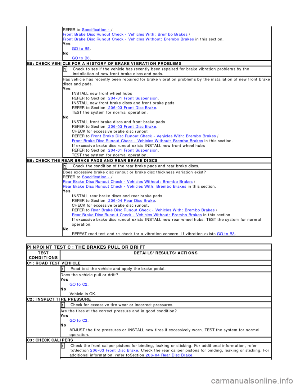
REFE
R to
Specification
- /
F r
ont Brake Disc Runout Check
- V
eh
icles With: Brembo Brakes
/
F
ront Brake Disc Runout Check
- V
e
hicles Without: Brembo Brakes
in this
section.
Yes GO to B5
.
No
GO to B6
.
B5: CHECK VEHICLE
FOR A HISTORY OF BRAKE VIBRATION PROBLEMS
Chec
k to se
e if the vehicle has recently been
repaired for brake vibration problems by the
installation of new front brake discs and pads.
1
Has vehicl
e has recently been repaired for brake vibrat
ion problems by the installation of new front brake
discs and pads.
Yes INSTALL new front wheel hubs
REFER to Section 204
-01 Fron
t Suspension
.
INST ALL new fr
ont brake disc
s and front brake pads
REFER to Section 206
-03 Fr
ont Disc Brake
.
TEST the system for normal
operation.
No INSTALL front brake discs and front brake pads
REFER to Section 206
-03 Fr
ont Disc Brake
.
CHECK for excessiv
e brake disc runout
REFER to Front Brake Disc Runout Check
- Veh
icles With: Brembo Brakes
/
F
ront Brake Disc Runout Check
- V
e
hicles Without: Brembo Brakes
in this
section.
If excessive brake disc runout exis ts INSTALL new front wheel hubs
REFER to Section 204
-01 Fron
t Suspension
.
TEST the system for normal
operation.
B
6:
CHECK THE REAR BRAKE PADS AND REAR BRAKE DISCS
Chec
k
the condition of the rear brake pads and rear brake discs.
1
D
o
es excessive brake disc runout or br
ake disc thickness variation exist?
REFER to Specification
- /
Rear B
rake Disc Runout Check
- Ve
hicles Without: Brembo Brakes
/
Rear
Brake Disc Runout Check
- Veh
icles With: Brembo Brakes
in this
section.
Yes INSTALL rear brake discs and rear brake pads
REFER to Section 206
-04
Rear Disc Brake
.
CHECK for excessiv
e brake disc runout.
REFER to Rear Brake Disc Runout Check
- Veh
icles With: Brembo Brakes
/
Rear
Brake Disc Runout Check
- V
e
hicles Without: Brembo Brakes
in this
section.
If excessive brake disc runout exists INSTALL ne w rear wheel hubs. TEST the system for normal
operation.
No REPEAT road test and re-check for a vi bration concern. If vibration exists GO to B3
.
PINPOINT TEST
C : THE BRAKES PULL OR DRIFT
TE
S
T
CONDITIONS
D E
TAILS/RESULTS/ACTIONS
C1
:
ROAD TEST VEHICLE
Road test th
e veh
icle and apply the brake pedal.
1
D
o
es the vehicle pull or drift?
Yes GO to C2
.
No
Vehicle is OK.
C2:
INS
PECT TIRE PRESSURE
Check f
or ex
cessive tire wear
or incorrect pressures.
1
Are the ti
res at the correct pressure and in good condition?
Yes GO to C3
.
No
AD
JUST the tire pressures or IN
STALL new tires if excessively wo rn. TEST the system for normal
operation.
C3 : CH
ECK CALIPERS
Check the fr
on
t caliper pistons for binding, leakin
g or sticking. For additional information, refer
toSection 206
-03 Fr
ont Disc Brake
. Check the rear cal
i
per pistons for
binding, leaking or sticking. For
additional information, refer toSection 206
-04
Rear Disc Brake
.
1
Page 313 of 2490
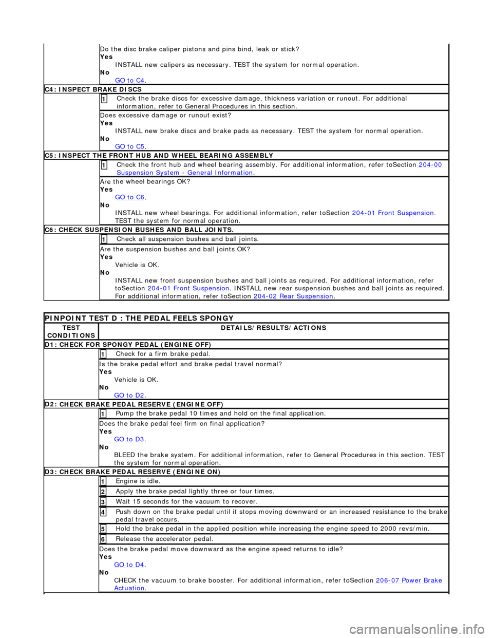
Do t
he disc brake caliper pistons
and pins bind, leak or stick?
Yes INSTALL new calipers as necessary. TE ST the system for normal operation.
No GO to C4
.
C4: INSPECT BR
AKE DISCS
Check the brake discs fo
r excess
ive damage, thickness variatio n or runout. For additional
information, refer to General Procedures in this section.
1
D
oes excessive damage or runout exist?
Yes INSTALL new brake discs and brak e pads as necessary. TEST the system for normal operation.
No GO to C5
.
C5: INSPECT THE FRONT HU
B AND WHEEL BEARING ASSEMBLY
Check the fr
ont hub and wheel bearing assembly.
For additional information, refer toSection 204
-00
Su
spension System
- General
Information
. 1
Are th
e wheel bearings OK?
Yes GO to C6
.
No
INSTALL new wheel bearings. For additional inform ation, refer toSection 204
-01
Front Suspension
.
TEST the system
for normal operation.
C
6: CHECK SUSPENSION BUSHES AND BALL JOINTS.
Chec
k all suspension bu
shes and ball joints.
1
Are th
e suspension bushes and ball joints OK?
Yes Vehicle is OK.
No INSTALL new front suspension bushes and ball joints as required. For additional information, refer
toSection 204
-01
Front Suspension
. INSTALL n
ew rear suspension bush
es and ball joints as required.
For additional informat ion, refer toSection 204
-0
2 Rear Suspension
.
P
INPOINT TEST D : THE PEDAL FEELS SPONGY
TE
ST
CONDITIONS
D
ETAILS/RESULTS/ACTIONS
D
1: CHECK FOR SPONGY PEDAL (ENGINE OFF)
Check f
or a firm brake pedal.
1
Is th
e brake pedal effort an
d brake pedal travel normal?
Yes Vehicle is OK.
No GO to D2
.
D2:
CHECK BRAKE PEDAL RESERVE (ENGINE OFF)
Pump th
e brake pedal 10 times and
hold on the final application.
1
Does th
e brake pedal feel fi
rm on final application?
Yes GO to D3
.
No
BLEED the brake system. For additional information, re fer to General Procedures in this section. TEST
the system for normal operation.
D3:
CHECK BRAKE PEDAL RESERVE (ENGINE ON)
Engine is
idle.
1
Apply the brake pedal ligh
tl
y three or four times.
2
W
ait 15 seconds for the vacuum to recover.
3
Push down on
the brake pedal until it stops moving
downward or an increased resistance to the brake
pedal travel occurs.
4
Hol
d the brake pedal in the applied position while increasing the engine speed to 2000 revs/min.
5
Re
lease the accelerator pedal.
6
Does th
e brake pedal move downward as
the engine speed returns to idle?
Yes GO to D4
.
No
CHECK the vacuum to brake booster. For additional information, refer toSection 206
-0
7 Power Brake
Actuation.
Page 317 of 2490
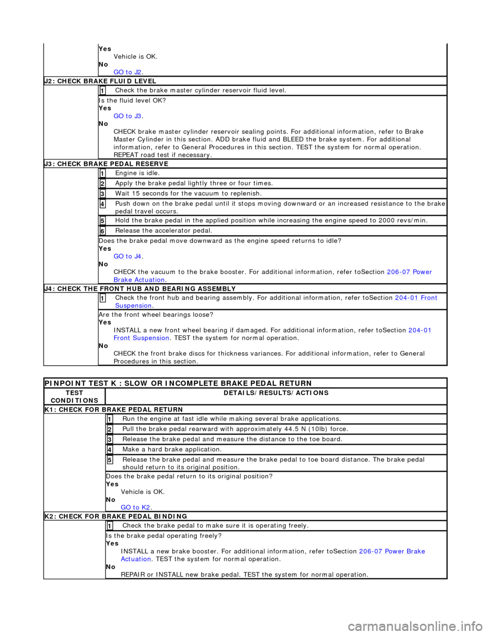
Yes
Vehicle is OK.
No GO to J2
.
J
2: CHECK BRAKE FLUID LEVEL
Check the brake master cyli
nder reservoir fluid level.
1
Is the fl
uid level OK?
Yes GO to J3
.
No
CHECK brake master cylinder reservoir sealing points. For additional information, refer to Brake
Master Cylinder in this section. ADD brake fl uid and BLEED the brake system. For additional
information, refer to General Proc edures in this section. TEST the system for normal operation.
REPEAT road test if necessary.
J
3: CHECK BRAKE PEDAL RESERVE
Engine is
idle.
1
Apply the brake pedal ligh
tl
y three or four times.
2
W
ait 15 seconds for the vacuum to replenish.
3
Push down on
the brake pedal until it stops moving
downward or an increased resistance to the brake
pedal travel occurs.
4
Hol
d the brake pedal in the applied position while increasing the engine speed to 2000 revs/min.
5
Re
lease the accelerator pedal.
6
Does th
e brake pedal move downward as
the engine speed returns to idle?
Yes GO to J4
.
No
CHECK the vacuum to the brake booster. Fo r additional information, refer toSection 206
-0
7 Power
Brake Ac
tuation
.
J
4: CHECK THE FRONT HUB AND BEARING ASSEMBLY
Check the fr
ont hub and bearing assembly. Fo
r additional information, refer toSection 204
-01
Front
Suspe
nsion
. 1
Are th
e front wheel bearings loose?
Yes INSTALL a new front wheel bearin g if damaged. For additional information, refer toSection 204
-01
F
ront Suspension
. TEST
the system for normal operation.
No CHECK the front brake discs for thickness variances. For additional information, refer to General
Procedures in this section.
PINPO
INT TEST K : SLOW OR INCOMPLETE BRAKE PEDAL RETURN
TE
ST
CONDITIONS
D
ETAILS/RESULTS/ACTIONS
K1: C
HECK FOR BRAKE PEDAL RETURN
Ru
n the engine at fast idle while
making several brake applications.
1
Pull the
brake pedal rearward with approximately 44.5 N (10lb) force.
2
Relea
se the brake pedal and measure
the distance to the toe board.
3
Make a hard brake
application.
4
Relea
se the brake pedal and measure the brake
pedal to toe board distance. The brake pedal
should return to its original position.
5
Does th
e brake pedal return
to its original position?
Yes Vehicle is OK.
No GO to K2
.
K
2: CHECK FOR BRAKE PEDAL BINDING
Check the brake pedal to make
s
ure it is operating freely.
1
Is th
e brake pedal operating freely?
Yes INSTALL a new brake booster. For addi tional information, refer toSection 206
-0
7 Power Brake
Actuation. TEST
the system for normal operation.
No REPAIR or INSTALL new brake pedal. TE ST the system for normal operation.
Page 346 of 2490

2.
Remove paper backing from pads to reveal adhesive
shim. Install brake pads, insert clip located on back of
inner pad into caliper piston.
3. Inst al
l caliper housing to caliper carrier.
Align hou
s
ing to carrier.
1. Install and tighten guide pins to 25-30 Nm.
2. Install dust covers.
3. Install anti-rattle spring.
4. NOTE : Th
e brake hose must only be installed with the vehicle's
body supported and the suspension hanging.
Install and tighten brake hose to caliper housing to 10-14 Nm.
5. NO
TE: Make sure the brake
hose does not twist when
tightening the hose lock-nut.
Connect brake hose to brake tube.
1. Position hose thread through bracket.
2. Install and tighten locking nut. Refer to Specifications, section 206-03.
3. Install and tighten brake- tube union nut. Refer to
Specifications, section 206-03.
6. Remove special tool from brake pedal.
7. Fit wheels. Refer to section 204-04.
8. NOTE: Make sure the brake hose is routed correctly.
Remove stands and lower vehicl e. Refer to section 100-02.
9. Bleed brake hydraulic system. See operation 70.25.03.
Page 350 of 2490

2.
Po
sition anti-rattle spring.
3. Install pins.
4. Install 'R' clips.
3. CAUTIO
N: The brake hose must
only be installed with the
vehicle's body supported and the suspension hanging.
Install brake hose to caliper.
Remove plugs f rom caliper and hose.
Instal
l new sealing washers.
Install and tigh
ten un
ion bolt to 22-26 Nm.
4.
NO
TE: Make sure the brake
hose does not twist when
tightening the hose lock-nut.
Connect brake hose to brake tube. 1. Position hose thread through bracket.
2. Install and tighten locking nut. Refer to Specifications, section 206-03.
3. Install and tighten brake- tube union nut. Refer to
Specifications, section 206-03.
5. Remove special tool from brake pedal.
6. Fit wheels. Refer to operation 74.20.05.
7. NOTE: Make sure the brake hose is routed correctly.
Remove stands and lower vehicl e. Refer to section 100-02.
8. Bleed brake hydraulic system. See operation 70.25.06.
Page 374 of 2490

In
stallation
11
. Remove brake
dust and clean
mating surfaces. See Warning
above.
1. Inst al
l caliper to hub carrier.
Install and tigh
ten bolts to 6
0 Nm.
2. CAUTI O
NS:
Retracting the caliper piston may cause the fluid reservoir
to over-flow. Remove brake flui d spillage immediately from paint
work with clean water.
Note the condition of the pi ns and replace if necessary.
Install brake pads. Refer to 70 .40.09 for anti-squeal grease
application.
Sl owly
retract caliper pistons.
1. Install pads.
2. Position anti-rattle spring.
3. Install pins - make sure pin collets are fully engaged
into caliper.
3. CAUTI O
NS:
The brake hose must only be installed with the vehicle's
body supported and the suspension hanging.
It is important that the brake hose is aligned correctly when
Page 375 of 2490
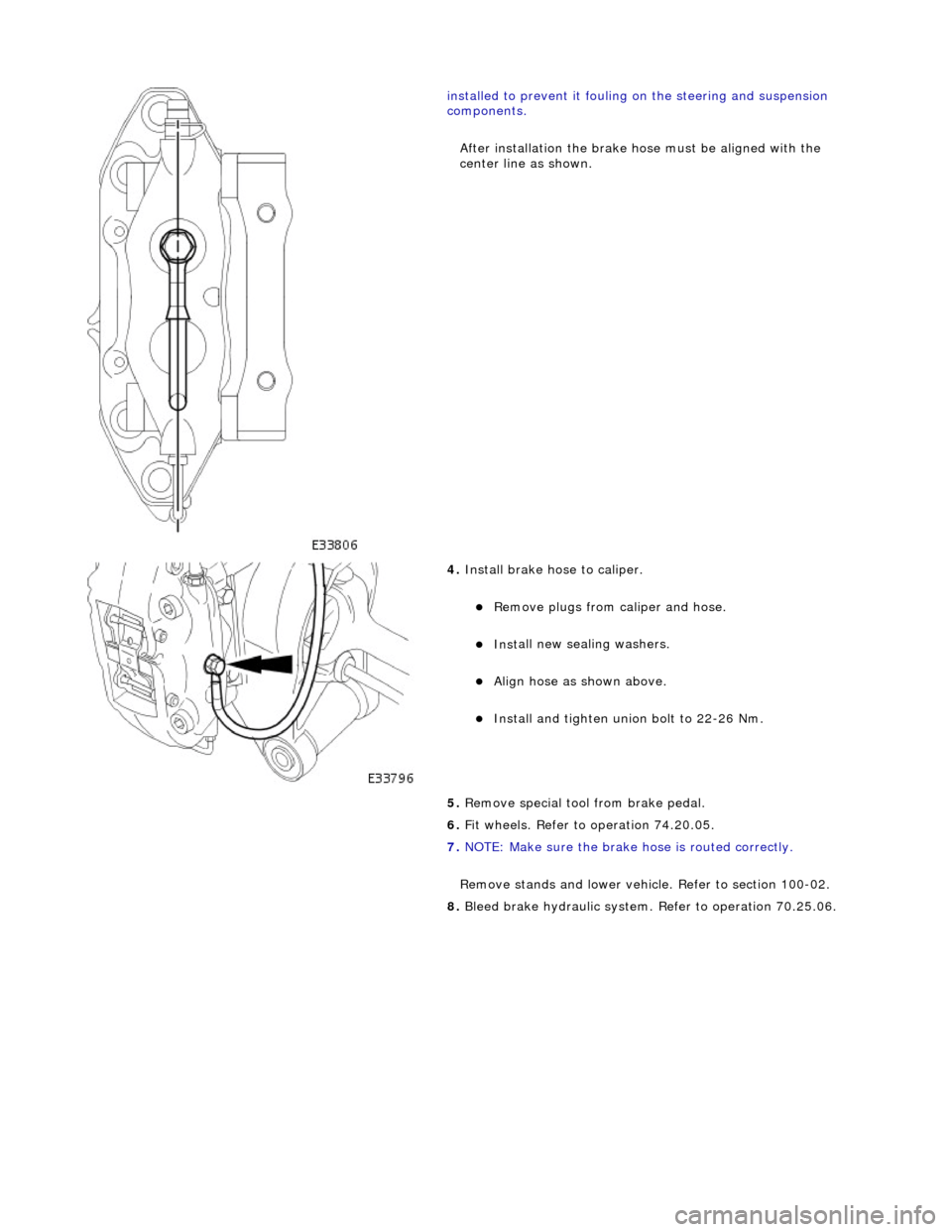
i
nstalled to prevent it fouling on the steering and suspension
components.
After installation the brake ho se must be aligned with the
center line as shown.
4. Install brake hose to
caliper.
Remove plugs f
rom caliper and hose.
Inst
all new sealing washers.
Align hos
e as shown above.
Install and tigh
ten union bolt to 22-26 Nm.
5. Remove special tool from brake pedal.
6. Fit wheels. Refer to operation 74.20.05.
7. NOTE: Make sure the brake hose is routed correctly.
Remove stands and lower vehicl e. Refer to section 100-02.
8. Bleed brake hydraulic system. Refer to operation 70.25.06.
Page 459 of 2490
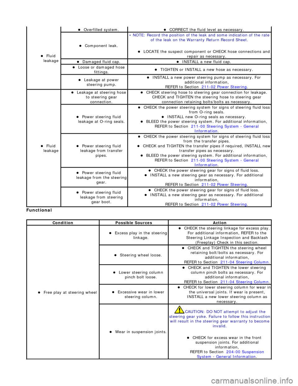
Function
al
Fl
uid
leakage
O
verfilled system.
CORRECT the
fluid leve
l as necessary.
Compon
ent leak.
•
NOTE: Record the position of the le
ak and some indication of the rate
of the leak on the Warra nty Return Record Sheet.
LOCATE
the suspect component or CHECK hose connections and
repair as necessary.
Damaged fluid cap. INST
ALL a new fluid cap.
Loose or damaged h
ose
fittings.
TI
GHTEN or INSTALL a new hose as necessary.
Leakage at
power
steering pump.
INST
ALL a new power steering
pump as necessary. For
additional information,
REFER to Section 211
-0
2 Power Steering
.
Fl
uid
leakage
Leakage
at steering hose
to steering gear connection.
CHECK
steering hose to
steering gear conn ection for leakage.
CHECK and TIGHTEN the steeri ng hose to steering gear
connection retaining bolt s/bolts as necessary.
Power steeri
ng fluid
leakage at O-ring seals.
CHECK
the power steering system fo
r signs of steering fluid loss
from O-ring seals.
INST
ALL new O-ring seals as necessary.
BLEE
D the power steering system.
For additional information,
REF
ER to Section 211
-0
0 Steering System
- Ge
neral
Informati
on
.
Power steeri
ng fluid
leakage from transfer pipes.
CHECK
the power steering system fo
r signs of steering fluid loss
from the transfer pipes.
CHECK
and TIGHTEN the transfer pipes if required, INSTALL new
transfer pipes as necessary.
BLEE
D the power steering system.
For additional information,
REF
ER to Section 211
-0
0 Steering System
- Ge
neral
Informati
on
.
Power steeri
ng fluid
leakage from the steering
gear.
CHECK
the power steering gear for signs of fluid loss.
INST
ALL a new steering gear as
necessary. For additional
information,
REFER to Section 211
-0
2 Power Steering
.
Power steeri
ng fluid
leakage from steering gear boot.
CHECK
the power steering gear for signs of fluid loss.
INST
ALL a new steering gear as
necessary. For additional
information,
REFER to Section 211
-0
2 Power Steering
.
Cond
ition
Possib
le Sources
Acti
on
F
ree play at steering wheel
Exce
ss play in the steering
linkage.
CHECK
the steering linkage for excess play.
For additional information, REFER to the
Steering Linkage Inspection and Backlash (Freeplay) Check in this section.
S
teering wheel loose.
CHECK
and TIGHTEN the steering wheel
retaining bolt/bolts as necessary. For additional information,
REFER to Section 211
-0
4 Steering Column
.
Lower steeri
ng column
pinch bolt loose.
CHECK
and TIGHTEN the lower steering
column pinch bolts as necessary. For additional information,
REFER to Section 211
-0
4 Steering Column
.
Exce
ssive wear in lower
steering column.
CHECK
for lower steering column for wear in
the universal joints. If wear is present,
INSTALL a new lower steering column as necessary.
W
ear in suspension joints.
CAU
TION: DO NOT attempt to adjust the
steering gear yoke. Failure to follow this instruction
will result in the steering gear warranty to become
invalid.
CHECK
for excess wear in the front
suspension joints. For additional information,
REFER to Section 204
-00
Suspension
Sy
stem
- General
Information
.
Page 460 of 2490
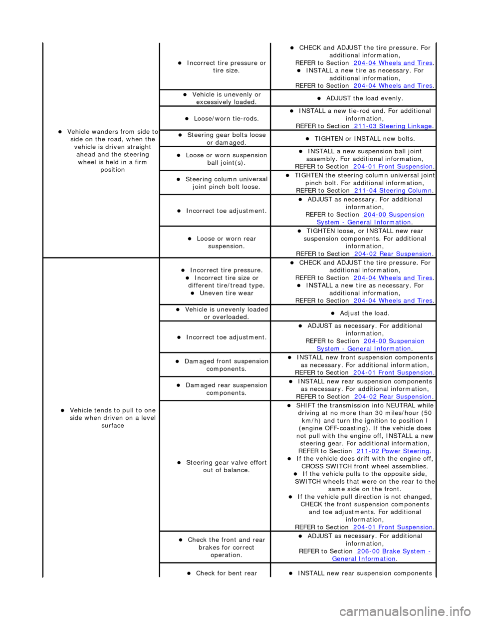
Vehicl
e wanders from side to
side on the road, when the vehicle is driven straight ahead and the steering wheel is held in a firm position
Incorrect ti re
pressure or
tire size.
CHECK and ADJ
UST the tire pressure. For
additional information,
REFER to Section 204
-0 4
Wheels and Tires
. IN
ST
ALL a new tire as necessary. For
additional information,
REFER to Section 204
-0 4
Wheels and Tires
.
Vehi
cl
e is unevenly or
excessively loaded.
A D
JUST the load evenly.
Loose/worn ti
e-
rods.
INST
ALL a ne
w tie-rod
end. For additional
information,
REFER to Section 211
-0 3
Steering Linkage
.
Steeri
ng gear bolts loose
o
r damaged.
TIGHTE
N or INSTALL
new bolts.
Loose or worn suspensi
on
ball jo
int(s).
INST
ALL a ne
w suspension ball joint
assembly. For additional information,
REFER to Section 204
-01 Fron
t Suspension
.
Steeri
ng column uni
versal
joint pinch bolt loose.
TI G
HTEN the steering column universal joint
pinch bolt. For additi onal information,
REFER to Section 211
-0 4
Steering Column
.
Incorre
ct
toe adjustment.
ADJUS
T as necessary. For additional
information,
REFER to Section 204
-00 Sus
pension
Sy
ste
m
- General
Information
.
Loose or worn rear
susp
ension.
TIGHTEN
loose, or IN
STALL new rear
suspension components. For additional information,
REFER to Section 204
-0 2
Rear Suspension
.
Vehicle t
e
nds to pull to one
side when driven on a level surface
Incorrect ti
re pressure.
Incorrect
ti
re size or
different tire/tread type.
Uneven tire wear
CHECK and ADJ
UST the tire pressure. For
additional information,
REFER to Section 204
-0 4
Wheels and Tires
. IN
ST
ALL a new tire as necessary. For
additional information,
REFER to Section 204
-04
Wheels and Tires
.
Vehicl
e is unevenly loaded
or overloaded.
Adjust the load
.
Incorre
ct
toe adjustment.
ADJUS
T as necessary. For additional
information,
REFER to Section 204
-00 Sus
pension
Sy
ste
m
- General
Information
.
Dam
a
ged front suspension
components.
I N
STALL new front suspension components
as necessary. For addi tional information,
REFER to Section 204
-01 Fron
t Suspension
.
Damaged rear
suspen
sion
components.
INST ALL ne
w rear suspension components
as necessary. For addi tional information,
REFER to Section 204
-0 2
Rear Suspension
.
Steeri
ng gear val
ve effort
out of balance.
SHIF T the
transmission into NEUTRAL while
driving at no more than 30 miles/hour (50 km/h) and turn the ignition to position I
(engine OFF-coasting). If the vehicle does
not pull with the engine off, INSTALL a new steering gear. For additional information,
REF E
R to Section 211
-0
2
Power Steering
. If t
he
vehicle does drift with the engine off,
CROSS SWITCH front wheel assemblies.
If the
vehicle pulls to
the opposite side,
SWITCH wheels that were on the rear to the
same side on the front.
If the v
ehicle pull dire
ction is not changed,
CHECK the front susp ension components
and toe adjustments. For additional information,
REFER to Section 204
-01 Fron
t Suspension
.
Chec
k
the front and rear
brakes for correct operation.
ADJUS
T as necessary. For additional
information,
REFER to Section 206
-0 0
Brake System
-
General Informati on.
Check fo
r bent rear
INST
ALL ne
w rear suspension components
Page 461 of 2490
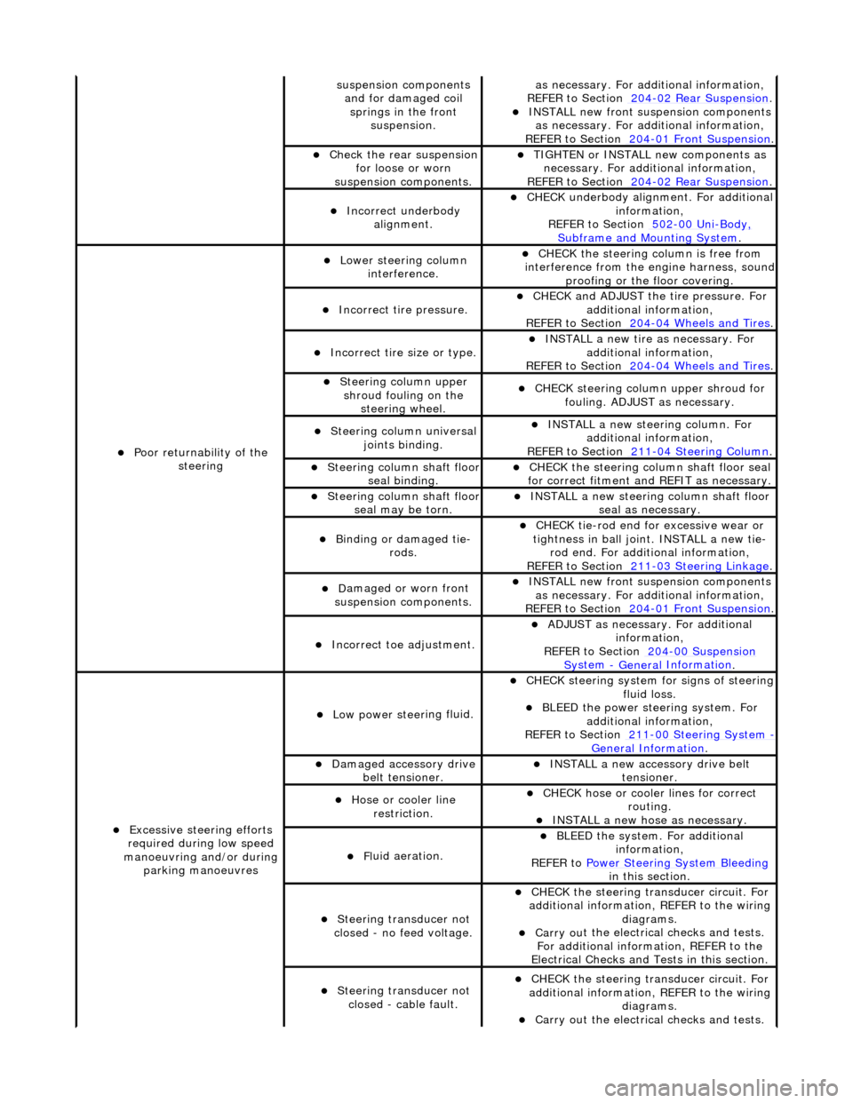
sus
pension components
and for damaged coil springs in the front suspension.
as necessary. For addi tional information,
REF
ER to Section 204
-0
2 Rear Suspension
. I
NSTALL new front suspension components
as necessary. For addi tional information,
REFER to Section 204
-01
Front Suspension
.
Chec
k the rear suspension
for loose or worn
suspension components.
TIGHTE
N or INSTALL new components as
necessary. For additi onal information,
REFER to Section 204
-0
2 Rear Suspension
.
Incorre
ct underbody
alignment.
CHECK
underbody alignment. For additional
information,
REFER to Section 502
-00
Uni
-Body, Subframe and M
ounting System
.
Poor r
eturnability of the
steering
Lower steeri
ng column
interference.
CHECK
the steering co
lumn is free from
interference from the en gine harness, sound
proofing or the floor covering.
Incorrect
tire pressure.
CHECK
and ADJUST the tire pressure. For
additional information,
REFER to Section 204
-0
4 Wheels and Tires
.
Incorrect
tire size or type.
IN
STALL a new tire as necessary. For
additional information,
REFER to Section 204
-0
4 Wheels and Tires
.
Steeri
ng column upper
shroud fouling on the steering wheel.
CHECK
steering column upper shroud for
fouling. ADJUST as necessary.
Steeri
ng column universal
joints binding.
IN
STALL a new steering column. For
additional information,
REFER to Section 211
-0
4 Steering Column
.
Steeri
ng column shaft floor
seal binding.
CHE
CK the steering column shaft floor seal
for correct fitm ent and REFIT as necessary.
Steeri
ng column shaft floor
seal may be torn.
IN
STALL a new steering column shaft floor
seal as necessary.
Bin
ding or damaged tie-
rods.
CHECK
tie-rod end for excessive wear or
tightness in ball joint. INSTALL a new tie- rod end. For additional information,
REFER to Section 211
-0
3 Steering Linkage
.
D
amaged or worn front
suspension components.
I
NSTALL new front suspension components
as necessary. For addi tional information,
REFER to Section 204
-01
Front Suspension
.
Incorre
ct toe adjustment.
AD
JUST as necessary. For additional
information,
REFER to Section 204
-00
Suspension
Sy
stem
- General
Information
.
Excessive steeri
ng efforts
required during low speed
manoeuvring and/or during parking manoeuvres
Low power steer
ing fluid.
CHE
CK steering system
for signs of steering
fluid loss.
BLEE
D the power steering system. For
additional information,
REFER to Section 211
-0
0 Steering System
- General Informati
on
.
Damaged accessory driv
e
belt tensioner.
INST
ALL a new accessory drive belt
tensioner.
Hose or cooler li
ne
restriction.
CHECK
hose or cooler lines for correct
routing.
INST
ALL a new hose as necessary.
Fl
uid aeration.
BLEE
D the system. For additional
information,
REFER to Power Steering System Bleeding
in t
his section.
Steeri
ng transducer not
closed - no feed voltage.
CHECK
the steering transducer circuit. For
additional information, REFER to the wiring diagrams.
Carry ou
t the electrical checks and tests.
For additional information, REFER to the
Electrical Checks and Tests in this section.
Steeri
ng transducer not
closed - cable fault.
CHECK
the steering transducer circuit. For
additional information, REFER to the wiring diagrams.
Carry ou
t the electrical checks and tests.