Suspension JAGUAR X308 1998 2.G Workshop Manual
[x] Cancel search | Manufacturer: JAGUAR, Model Year: 1998, Model line: X308, Model: JAGUAR X308 1998 2.GPages: 2490, PDF Size: 69.81 MB
Page 463 of 2490
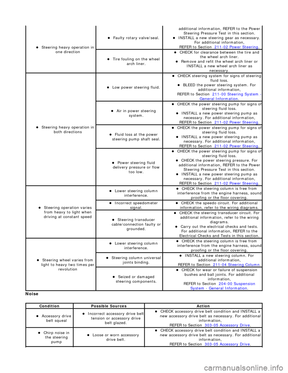
No
ise
S
teering heavy operation in
one direction
F
aulty rotary valve/seal.
addi
tional information, REFER to the Power
Steering Pressure Test in this section.
INST
ALL a new steering
gear as necessary.
For additional information,
REFER to Section 211
-0
2 Power Steering
.
Ti
re fouling on the wheel
arch liner.
CHECK for
clearance be
tween the tire and
the wheel arch liner.
R
emove and refit the wheel arch liner or
INSTALL a new wheel arch liner as necessary.
S
teering heavy operation in
both directions
Low power steer
ing fluid.
CHE
CK steering system
for signs of steering
fluid loss.
BLEE
D the power steering system. For
additional information,
REFER to Section 211
-0
0 Steering System
- General Informati
on
.
Ai
r in power steering
system.
CHECK
the power steering pump for signs o
f steering fl
uid loss.
INST
ALL a new power steering pump as
necessary. For additi onal information,
REFER to Section 211
-0
2 Power Steering
.
Fluid loss at the power
steering pump shaft seal.
CHECK
the power steering pump for signs o
f steering fl
uid loss.
INST
ALL a new power steering pump as
necessary. For additi onal information,
REFER to Section 211
-0
2 Power Steering
.
Power steeri
ng fluid
delivery pressure or flow too low.
CHECK
the power steering pump for signs o
f steering fl
uid loss.
CHECK
the power stee
ring pressure. For
additional information, REFER to the Power Steering Pressure Test in this section.
INST
ALL a new power steering pump as
necessary. For additi onal information,
REFER to Section 211
-0
2 Power Steering
.
Steeri
ng operation varies
from heavy to light when
driving at constant speed
Lower steeri
ng column
interference.
CHECK
the steering co
lumn is free from
interference from the en gine harness, sound
proofing or the floor covering.
Incorre
ct sp
eedometer
signal.
CHECK
the speedo circ
uit. For additional
information, refer to the wiring diagrams.
Steeri
ng transducer
cable/connection faulty or grounded.
CHECK
the steering transducer circuit. For
additional information, refer to the wiring diagrams.
Carry ou
t the electrical checks and tests.
For additional information, REFER to the
Electrical Checks and Tests in this section.
Steeri
ng wheel varies from
light to heavy two times per revolution
Lower steeri
ng column
interference.
CHECK
the steering co
lumn is free from
interference from the en gine harness, sound
proofing or the floor covering.
Steeri
ng column universal
joints binding.
IN
STALL a new steering column. For
additional information,
REFER to Section 211
-0
4 Steering Column
.
Seized or damaged
ste
ering components.
CHECK
for wear or failure of suspension
bushes and ball join ts. For additional
information,
REFER to Section 204
-00
Suspension
Sy
stem
- General
Information
.
Cond
ition
Possib
le Sources
Acti
on
Acce
ssory drive
belt squeal
Incorre
ct accessory drive belt
tension or accessory drive belt glazed.
CHECK
accessory drive belt condition and INSTALL a
new accessory drive belt as necessary. For additional
information,
REFER to Section 303
-0
5 Accessory Drive
.
Chir
p noise in
the steering pump
Loose or worn accessory dr
ive belt.
CHECK
accessory drive belt condition and INSTALL a
new accessory drive belt as necessary. For additional
information,
REFER to Section 303
-0
5 Accessory Drive
.
Page 465 of 2490

Description of General Stee
ring System Noises
Boom
Rh
ythmic sound like a drum roll or distant
thunder. May cause pressure on the ear drum.
Buzz
Low-pitched soun
d, like a bee. Usually associated with vibrations.
Chatt
er
Rapidly rep
eating
metallic sound.
Chuckle
Rapid noise that soun
ds like
a stick against the spokes of a spinning bicycle wheel.
F
eedback (knocking noises in the
steering gear) - condition where roughness is felt in the steering
wheel by the driver when the vehicle
is driven over rough surfaces
REF
ER to Section 211
-0
3 Steering Linkage
.
Steeri
ng gear
retaining bolts
loose or damaged.
CAU
TION: DO NOT attempt to adjust the
steering gear yoke. Failure to follow this instruction
will result in the steering gear warranty to become
invalid.
CHECK
and TIGHTEN the steering gear
retaining bolts.
INST
ALL new retaining bolts as necessary.
For additional information,
REFER to Section 211
-0
2 Power Steering
.
L
oose suspension
bushing, bolts or ball joints.
TIGHTE
N or INSTALL new components as
necessary. For additi onal information,
REFER to Section 204
-01
Front Suspension
.
Steeri
ng column
retaining bolts loose.
CAU
TION: DO NOT attempt to adjust the
steering gear yoke. Failure to follow this instruction
will result in the steering gear warranty to become
invalid.
CHECK
and TIGHTEN the steering column
retaining bolts/nuts and pinch bolts if required. For additional information,
REFER to Section 211
-0
4 Steering Column
.
Exce
ssive wear in
steering column assembly.
CHECK
for steering column for wear in the
universal joints and be arings. If wear is
present, INSTALL a new steering column as
necessary. For additi onal information,
REFER to Section 211
-0
4 Steering Column
.
Ni
bble (Shimmy) Oscillation of the
steering wheel (not vertical which is SHAKE). This is driven by road wheel imbalance.
Road wh
eel
imbalance.
CHECK
for road wh
eel imbalance.
CHECK for
rele
vant SERVICE
BULLETINS/SERVICE ACTIONS for the
vehicle on Jaguar Communications Online (JCOL) or in hard copy form.
S
teering wheel
replacement.
CHECK for
rele
vant SERVICE
BULLETINS/SERVICE ACTIONS for the
vehicle on Jaguar Communications Online (JCOL) or in hard copy form.
Rac
k replacement.
CHECK for
rele
vant SERVICE
BULLETINS/SERVICE ACTIONS for the
vehicle on Jaguar Communications Online (JCOL) or in hard copy form.
Page 468 of 2490
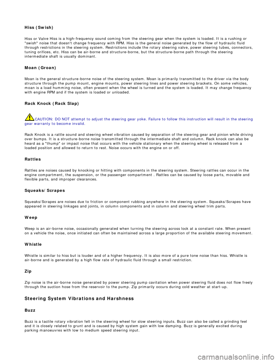
Hiss (Swish)
Hiss or Val
ve Hiss is a high-frequency so
und coming from the steering gear when the system is loaded. It is a rushing or
"swish" noise that doesn't change frequency with RPM. Hiss is the general noise generated by the flow of hydraulic fluid
through restrictions in the steer ing system. Restrictions include the rotary stee ring valve, power steering tubes, connectors,
tuning orifices, etc. Hiss can be air- borne and structure-borne, but the structure-borne path through the steering
intermediate shaft is usually dominant.
Moan (Groan)
Moan is the general structu r
e-borne noise of the steering system. Moan is primarily transmitted to the driver via the body
structure through the pump mount, engine mounts, power steering lines and power steering brackets. On some vehicles,
moan is a load humming noise, often present when the wheel is turned and the system is loaded. It may change frequency
with engine RPM and if the sy stem is loaded or unloaded.
Rack Knock (R
ack Slap)
CAU
T
ION: DO NOT attempt to adjust the stee
ring gear yoke. Failure to follow this instruction will result in the steering
gear warranty to become invalid.
Rack Knock is a rattle sound an d steering wheel vibration caused by separation of the steering gear and pinion while driving
over bumps. It is a structure-borne noise transmitted throug h the intermediate shaft and column. Rack knock can also be
heard as a "thump" or impact noise that occurs with the vehicle stationary when the steering wheel is released from a
loaded position and allowed to return to rest . Noise occurs with the engine on or off.
Rattles
Ra
ttles are noises caused by knocking or hitting with components in the steering system. Steering rattles can occur in the
engine compartment, the suspension, or the passenger compartment . Rattles can be caused by loose parts, movable and
flexible parts, and improper clearances.
Squea k
s/Scrapes
Squeaks/Scrapes are noises due
to fri
ction or component rubbi
ng anywhere in the steering system. Squeaks/Scrapes have
appeared in steering linkages and jo ints, in column components and in co lumn and steering wheel trim parts.
Weep
We
ep is an air-borne noise, occasionally
generated when turning the steering across lock at a constant rate. When present
on a vehicle the noise, once initiated can often be maintained across a large proportion of the available steering movement.
Whistle
Wh
istle is similar to hiss but is louder and of a higher frequency. It is also more
of a pure tone noise than hiss. Whistle is
air-borne and is generated by a high flow rate of hydraulic fluid through a small restriction.
Zip
Zip n
o
ise is the air-borne noise
generated by power steerin g pump cavitation when power steering fluid does not flow freely
through the suction hose from the rese rvoir to the pump. Zip primarily occurs during cold weather at start-up.
Steering System Vibrations and Harshne
ss
Buzz
Buzz is a tactile rotary vi
bration felt in
the steering wheel for slow steering inputs. Buzz can also be called a grinding feel
and it is closely related to grunt and is caused by high system gain with low damping. Buzz is generally excited during
parking manoeuvres with low to medium speed steering input.
Page 469 of 2490
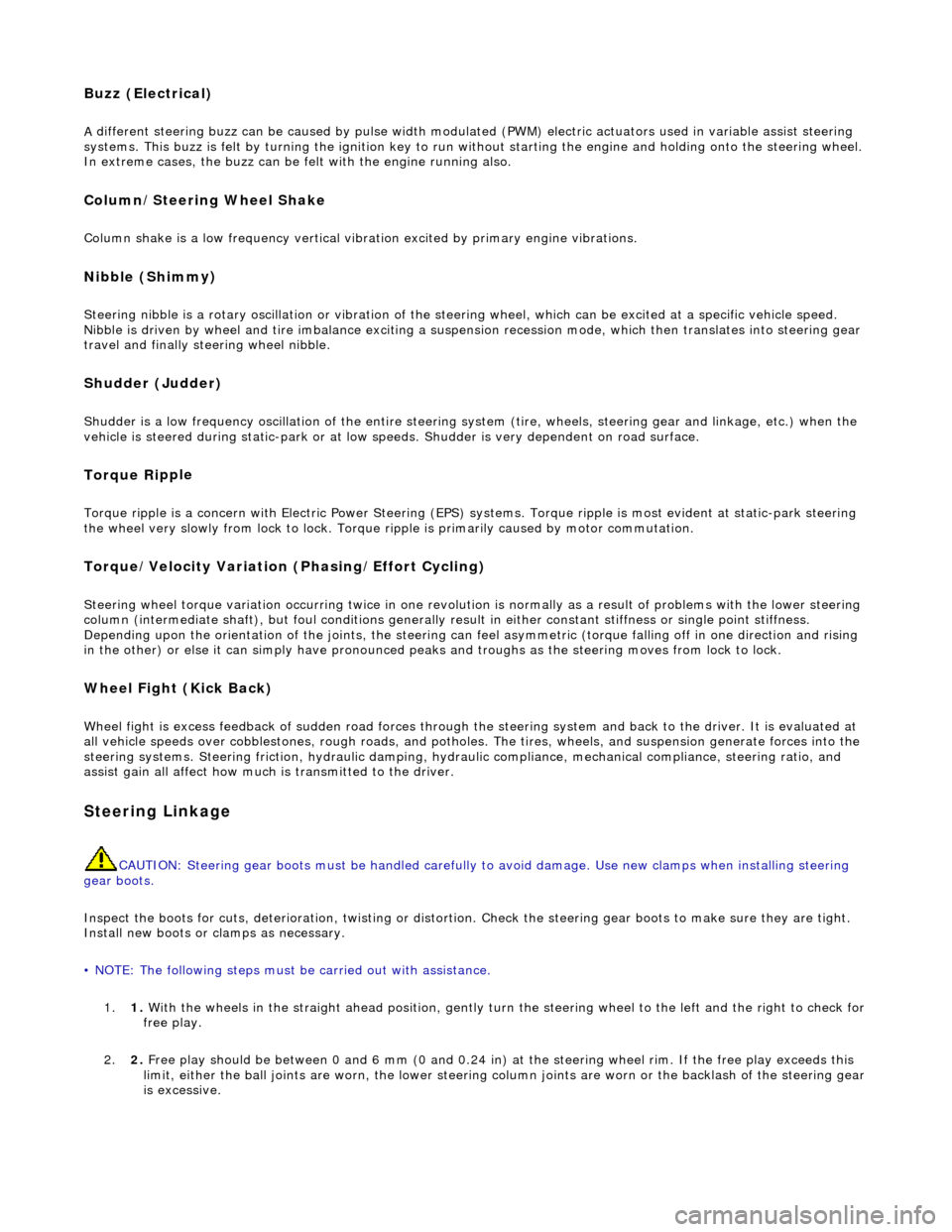
Buzz (E
lectrical)
A
different steering buzz can be caused by
pulse width modulated (PWM) electric actuators used in variable assist steering
systems. This buzz is felt by turning the ignition key to run without starting the engine and holding onto the steering wheel.
In extreme cases, the buzz can be felt with the engine running also.
Column/Steering Wheel
Shake
Column shake is a low f
requenc
y vertical vibration excited by primary engine vibrations.
Nibble (Shimm
y)
Steeri
ng nibble is a rotary oscillation or
vibration of the steering wheel, which can be excited at a specific vehicle speed.
Nibble is driven by wheel and tire imbalance exciting a suspensi on recession mode, which then translates into steering gear
travel and finally steering wheel nibble.
Shudder (Judd
er)
Shudder i
s a low frequency oscillation of th
e entire steering system (tire, wheels, st eering gear and linkage, etc.) when the
vehicle is steered during static-park or at low sp eeds. Shudder is very dependent on road surface.
Torque Ri
pple
Torque rippl
e is a concern with Electric Power Steering (EPS) sy
stems. Torque ripple is most evident at static-park steering
the wheel very slowly from lock to lock. Torque ripple is primarily caused by motor commutation.
Torque/Veloc
ity Variation
(Phasing/Effort Cycling)
Steeri
ng wheel torque variation oc
curring twice in one revolution is normally as a result of problems with the lower steering
column (intermediate shaft), but foul cond itions generally result in either constant stiffnes s or single point stiffness.
Depending upon the orientation of the joints, the steering can fe el asymmetric (torque falling off in one direction and rising
in the other) or else it can simply have pronounced peaks and troughs as the steering moves from lock to lock.
Wheel Fight
(Kick Back)
W
heel fight is excess feedback of sudden road forces through th
e steering system and back to the driver. It is evaluated at
all vehicle speeds over cobblestones, rough roads, and potholes . The tires, wheels, and suspension generate forces into the
steering systems. Steering friction, hydraulic damping, hydr aulic compliance, mechanical compliance, steering ratio, and
assist gain all affect how much is transmitted to the driver.
Stee
ring Linkage
CAUTI
ON: Steering gear boots must be
handled carefully to avoid damage. Use new clamps when installing steering
gear boots.
Inspect the boots for cuts, deterioration, tw isting or distortion. Check the steering gear boots to make sure they are tight.
Install new boots or clamps as necessary.
• NOTE: The following steps must be carried out with assistance.
1. 1. With the wheels in the straight ahead po sition, gently turn the steering wheel to the left and the right to check for
free play.
2. 2. Free play should be between 0 and 6 mm (0 and 0.24 in) at the steering wheel rim. If the free play exceeds this
limit, either the ball joints are worn, the lower steering column joints are worn or the backlash of the steering gear
is excessive.
Page 477 of 2490

Stee
ring System - General Informat
ion - Steering Gear Centralizing
Gen
eral Procedures
Rack Al
ignment Markers
1.
The steering rack should al
ways
be centralized prior to steering
column or suspension geometry adjustment.
Central
ization of the steering ra
ck is achieved by aligning
the marker on the centralizing cap with a locator on the
pinion housing.
Page 478 of 2490
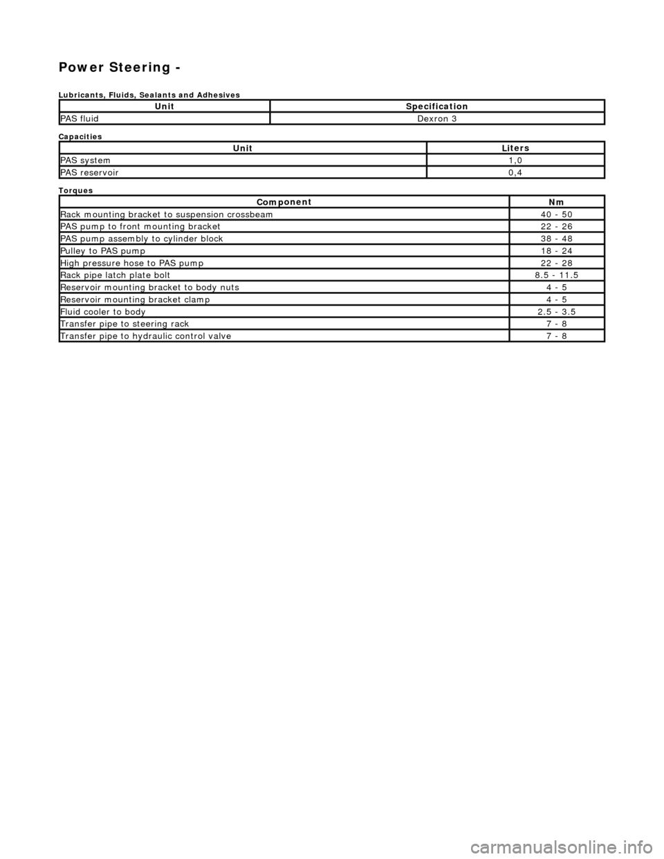
Power Steering -
Lubric
ants, Fluids, Sealants and Adhesives
Capacities
Torques
UnitSp
ecification
PAS flu
i
d
De
xr
on 3
UnitLi
t
ers
PAS syste
m1,0
PAS reservoi
r0,4
Com p
onent
Nm
Rac
k
mountin
g brac
ke
t to suspension crossbeam
40
- 50
PAS pump to front mounti
ng bracket
22
-
26
P
AS pu
mp assembly to cylinder block
38
-
48
Pul
l
ey to PAS pump
18
-
24
Hi
gh pressure hose to PAS pump22 -
28
Rack
pipe latch plate bolt8.5 -
11.5
R
e
servoir mounting bracket to body nuts
4 -
5
R
e
servoir mounting bracket clamp
4 -
5
Fluid cooler to body2.
5 -
3.5
Transfer pipe
to steering rack7 -
8
Transfer pipe
to hydraulic con
trol valve
7 -
8
Page 480 of 2490

The steering rack assembly :
Is mounted on the
rear face of the
front suspension crossbeam by two forg ed mounting brackets with resilient
bushes. The bushes are handed (pinion side and non-pinion side) and are orientated according to the vehicle range
application.
Convert s
the rotary motion of the steering wheel, via the steering gear pinion, to the lateral motion of the rack.
F
e
atures a variable ratio steering
rack with integral hydraulic po wer steering cylinder and piston.
Has a hydrauli
c control valve with Servotronic co
ntrol and positive center feel torsion bar.
The basic steering rack assembly is not serviceable. The following components are serviceable items:
Transfer pipework
.
Servotronic valve. Cent
ralizing cap.
O
u
ter ball joint.
Rac
k
gaiter.
Clips and
fittings.
Steering Rack Components
It e
m
Par
t
Number
De
scr
iption
1—Front
su
spension crossbeam
2—Steeri
ng rack housi
ng
3—Hydraulic
control valve housing
4—Moun
ting bracke
t
5—Gait
er
6—Tie
rod
7—O
u
ter ball joint
Steering R
a
ck Assembly
Page 488 of 2490
The rotary distri
butor and control sleeve turn relative to ea
ch other, forming the unequal restrictions which create the
differential pressures to operat e the rack piston; the displacement of the di stributor and sleeve being controlled by the
elastic deformation of a torsion bar which is concentric with the pinion and valve. Refer to Positive Center-Feel Torsion Bar
in this sub-sectio n.
The hydraulic reaction piston moves axially, relative to th e rotary distributor, and is connected to the control sleeve by a
three-bearing helical screw. Pressure applied either side of the hydraulic reaction piston is translated into a rotational force
which increases steering effort. For detail s of Servotronic speed-sensitive steering control, refer to Servotronic Control in
this sub-section.
When the vehicle is travelling straight ah ead, the valve restrictions are balanced, thus providing equal pressures on either
side of the rack piston. When load is a pplied at the steering wheel, the two halves of the control valve (rotary distributor
and control sleeve) are displaced making the restrictions unequa l. The resulting differential pressures on either side of the
rack piston, assist the steering rack to mo ve to left or right. As the turning load is removed, the pressures equalize again
and the steering return s to the straight ahead position , aided by suspension geometry.
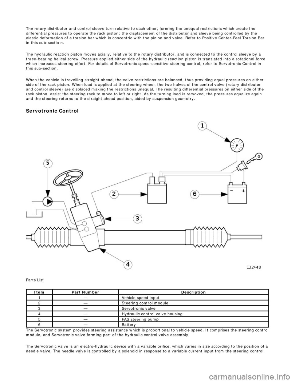
Serv
otronic Control
P a
rts List
The Servotronic system provides steering assistance which is pr oportional to vehicle speed. It comprises the steering control
module, and Servotronic valve forming part of the hydraulic control valve assembly.
The Servotronic valve is an electro-hydrauli c device with a variable orifice, which varies in size according to the position of a
needle valve. The needle valve is controlled by a solenoid in response to a variable current input from the steering control
Ite
m
Part
Number
Descr
iption
1—Vehi
cl
e speed input
2—Steeri
ng control
module
3—Servotronic valve
4—Hydraulic
control valve housing
5—PAS stee
rin
g pump
6—Batt
ery
Page 489 of 2490
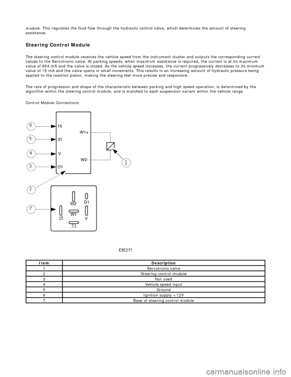
modul
e. This regulates the fluid flow
through the hydraulic control valve, wh ich determines the amount of steering
assistance.
Steering Control Module
The steering control
module re
ceives the vehicle speed from the instrument cluster and outputs the corresponding current
values to the Servot ronic valve. At parking speeds, wh en maximum assistance is required , the current is at its maximum
value of 854 mA and the valve is closed. As the vehicle speed increases, the current progressively decreases to its minimum
value of 15 mA and the valve opens in sma ll increments. This results in an increasing amount of hydraulic pressure being
applied to the reaction piston, making the steering feel more precise and responsive.
The rate of progression and shape of the characteristic between parking and high speed operation, is determined by the
algorithm within the steering control module, and is matched to each suspension variant within the vehicle range.
Control Module Connections
It
em
De
scription
1Servotronic valve
2Steeri
ng control module
3No
t used
4Vehi
cle speed input
5Ground
6Ignition su
pply +12V
7Base of
steering control module
Page 510 of 2490
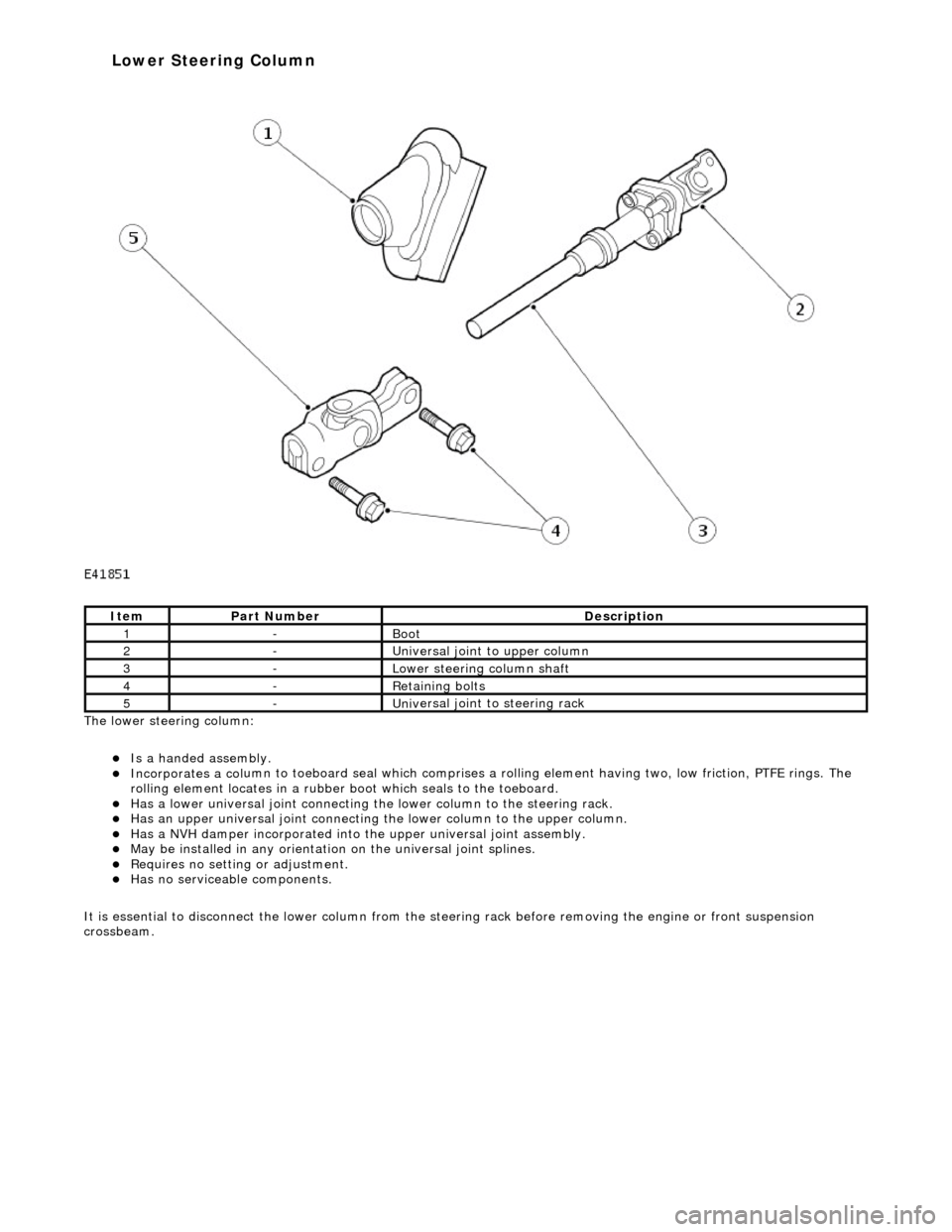
The lower steeri ng col
umn:
Is a han
ded assembly
.
Incorporates
a col
umn to toeboard seal
which comprises a rolling element having two, low friction, PTFE rings. The
rolling element locates in a rubber b oot which seals to the toeboard.
Has a lowe
r universal joint connecting the
lower column to the steering rack.
Has an upper un
iversal joint connecting
the lower column to the upper column.
Has a NVH damper in
corporated into
the upper universal joint assembly.
May be installed in an
y orientation on the universal joint splines.
R
e
quires no setting or adjustment.
Has no s
e
rviceable components.
It is essential to disconnect the lower column from the steer ing rack before removing the engine or front suspension
crossbeam.
It e
m
Par
t
Number
De
scr
iption
1-Boot
2-Uni
v
ersal joint to upper column
3-Lower steeri
ng col
umn shaft
4-R
e
taining bolts
5-Uni
v
ersal joint to steering rack
Lower Steering Column