JAGUAR X308 1998 2.G Workshop Manual
Manufacturer: JAGUAR, Model Year: 1998, Model line: X308, Model: JAGUAR X308 1998 2.GPages: 2490, PDF Size: 69.81 MB
Page 1051 of 2490

The
automatic belt tensioner consists of an idler pulley which is
free to rotate on a bearing, located at the end of a spring-
loaded pivot arm.
The pivot arm can be turned counter-clockwise (viewed from th e front of the engine) for belt removal and installation.
A belt-wear indicator is incorporated on th e rear horizontal face of the pivot arm.
It
em
De
scription
1Bel
t Wear Indicator
2Re
new Belt Indicator
3N
ew Belt Maximum Length
4N
ew Belt Minimum Length
Au
tomatic Belt Tensioner
Page 1052 of 2490

P a
rts List
All engine accessories are rigidly-mounted onto the cylinder block by means of accessory moun ting brackets on the left and
right-hand sides of the engine.
The left-hand bracket supports the air-cond itioning compressor and steering pump.
The right-hand bracket su pports the generator.
Dowels between the accessory mounting br ackets and the engine ensure that the accessory pulleys are accurately aligned
with the accessory drive belt.
A ccess
ory Drive on Supercharged Engines
The front
en
d accessory drive description and information for the
supercharged engine is identical to that given above. The
only difference is that the drive belt for the supercharger passes im mediately in front of the accessory drive belt. Therefore,
before any work can be done on the acce ssory drive belt and associated components, the supercharg er drive belt must first
be removed.
It e
m
Par
t
Number
De
scr
iption
1—R
i
ght Hand Mounting Bracket
2—Left H
and Mounting Bracket
Access
ory Mounting Brackets
Page 1053 of 2490

Accessory Drive - Acce
ssory
Drive Belt4.0L NA V8 - AJ27/3.2L NA V8 -
AJ26
Re
moval and Installation
Remov
al
Installation
1.
O
pen the engine compartment and fit paintwork protection
sheets.
2. Check the belt wear indicator ma rks to confirm that the drive
belt is / is not within limits.
3. CAUTI
ON: When releasing the
belt tension, never apply
any torque in a clockwise direction to the pulley ce ntre bolt (left
hand thread) as it could subsequently loosen.
Remove the drive belt fro m the accessory drive.
1. Use a spanner e.g. Churchill JD-230 or Snap On XDHM 1415, on the centre bo lt of the belt tensioner
idler pulley, to turn the adju ster assembly to the left,
viewed from the front, against spring tension.
2. Whilst holding the tensioner against spring tension, remove the drive belt from the generator pulley.
Release the tensioner sl owly and remove the
spanner.
D
isconnect the belt from the ot
her pulleys, as necessary.
1. In
stallation is the
reverse of the remova l procedure. Ensure
that the belt is correctly and sq uarely located on each pulley.
Page 1054 of 2490

Accessory Drive - Accessory Drive Belt
4.0L SC V8 - AJ26
Re
mo
val and Installation
Remov
a
l
Installation
1.
Op
en the engine compartment and fit paintwork protection
sheets.
2. Remove the supercharger driv e belt, for access. Refer to
operation 18.50.08.
3. Check the belt wear indicator ma rks to confirm that the drive
belt is / is not within limits.
4. CAUTIO
N: When releasing the
belt tension, never apply
any torque in a clockwise direction to the pulley ce ntre bolt (left
hand thread) as it could subsequently loosen.
Remove the drive belt fro m the accessory drive.
1. Use a spanner e.g. Churchill JD-230 or Snap On XDHM 1415, on the centre bo lt of the belt tensioner
idler pulley, to turn the adju ster assembly to the left,
viewed from the front, against spring tension.
2. Whilst holding the tensioner against spring tension, remove the drive belt from the generator pulley.
Release the tensioner sl owly and remove the
spanner.
D i
sconnect the belt from the ot
her pulleys, as necessary.
1. Ins
tallation is the
reverse of the remova l procedure. Ensure
that the belt is correctly and sq uarely located on each pulley.
2. Refit the supercharger drive belt. Refer to operation 18.50.08.
Page 1055 of 2490

Accessory Drive - Acce
ssory
Drive Belt Idler Pulley4.0L NA V8 - AJ27/3.2L
NA V8 - AJ26
Re
moval and Installation
I
nstallation
1.
O
pen the engine compartment and fit paintwork protection
sheets.
2. Remove the drive belt for access. Refer to Operation
(12.10.40)
3. R
emove the idler pulley.
1. Remove the securing bolt from the idler pulley.
2. Remove the idler pulley.
1. Installation is the reverse of the removal procedure. Tighten
the pulley securing bolt to 53-69 Nm. Ensure that the belt is
correctly and squarely lo cated on each pulley.
Page 1056 of 2490

Accessory Drive - Accessory Drive Belt
Idler Pulley4.0L SC V8 - AJ26
Re
mo
val and Installation
I
n
stallation
1.
Op
en the engine compartment and fit paintwork protection
sheets.
2. Remove the supercharger driv e belt, for access. Refer to
operation 18.50.08.
3. Remove the accessory drive belt for access. Refer to Operation
(12.10.40)
4. Re
move the idler pulley.
1. Remove the securing bolt from the idler pulley.
2. Remove the idler pulley.
1. Installation is the reverse of the removal procedure. Tighten
the pulley securing bolt to 53-69 Nm. Ensure that the belt is
correctly and squarely lo cated on each pulley.
2. Refit the supercharger drive belt. Refer to operation 18.50.08.
Page 1057 of 2490

Accessory Drive - Acce
ssory
Drive Belt Tensioner4.0L NA V8 - AJ27/3.2L
NA V8 - AJ26
Re
moval and Installation
I
nstallation
1.
R
emove the drive belt for access. Refer to Operation
(12.10.40)
2. Re
move the tensioner assembly, which includes the tensioner
pulley..
1. Remove the bolt whic h secures the tensioner
assembly to the engine.
2. Remove the tensioner assembly.
1. Installation is the reverse of the removal procedure. Tighten
the tensioner assembly securing bolt to 38-48 Nm. Ensure that
the belt is correctly and squa rely located on each pulley.
Page 1058 of 2490

Accessory Drive - Accessory
Drive Belt Tensioner4.0L SC V8 - AJ26
Re
mo
val and Installation
I
n
stallation
1.
Op
en the engine compartment and fit paintwork protection
sheets.
2. Remove the supercharger driv e belt, for access. Refer to
operation 18.50.08.
3. Remove the accessory drive belt for access. Refer to Operation
(12.10.40)
4. Remove t
he tensioner assembly, which includes the tensioner
pulley..
1. Remove the bolt whic h secures the tensioner
assembly to the engine.
2. Remove the tensioner assembly.
1. Installation is the reverse of the removal procedure. Tighten
the tensioner assembly securing bolt to 38-48 Nm. Ensure that
the belt is correctly and squa rely located on each pulley.
2. Refit the supercharger drive belt. Refer to operation 18.50.08.
Page 1059 of 2490

Ac
cessory Drive - Supercharger Belt
Re
moval and Installation
Remov
al
Installation
1.
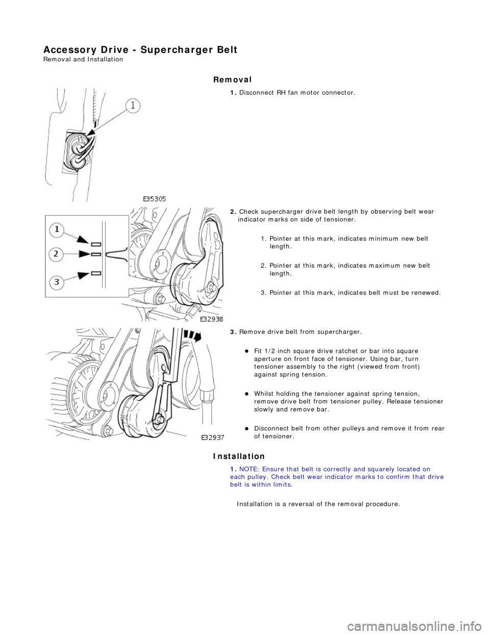
Di
sconnect RH fa
n motor connector.
2. Check superch
arger dr
ive belt length by observing belt wear
indicator marks on side of tensioner.
1. Pointer at this mark, indicates minimum new belt length.
2. Pointer at this mark, indicates maximum new belt length.
3. Pointer at this mark, indi cates belt must be renewed.
3. R
emove drive belt from supercharger.
F
it 1/2 inch square drive ratchet or bar into square
aperture on front face of tensioner. Using bar, turn
tensioner assembly to the right (viewed from front)
against spring tension.
Wh
ilst holding the tensione
r against spring tension,
remove drive belt fr om tensioner pulley. Release tensioner
slowly and remove bar.
D
isconnect belt from
other pulleys and remove it from rear
of tensioner.
1. NOTE: Ensure that belt is correctly and squarely located on
each pulley. Check belt wear indicator marks to confirm that drive
belt is within limits.
Installation is a reversal of the removal procedure.
Page 1060 of 2490

Access
ory Drive - Supercharger Belt Idler Pulley
Re
mo
val and Installation
Remov
a
l
Installation
1.
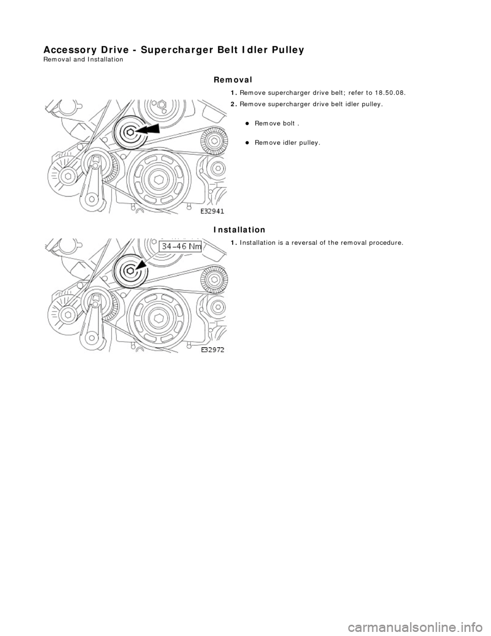
Re
move supercharger drive belt; refer to 18.50.08.
2. Re
move supercharger drive belt idler pulley.
Re
mo
ve bolt .
R
e
move idler pulley.
1. Installation
is a reversal
of the removal procedure.